Advertisement
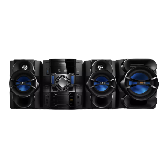
Seu Mini Hi-Fi System
TABLE OF CONTENTS
Technical specification ...........................................................1-16
Safety instruction......................................................................2-1
ESD protection......... ................................................................2-2
Set Block diagram ...................................................................3-1
Set Wiring diagram ..................................................................4-1
Disassembly diagram ..........................................................5-1-2
Layout diagram.................................................................6-2..6-3
Key & Display
Layout diagram.................................................................7-2..7-5
Mechanical Exploded view..... .......................................... .....11-1
©
Copyright 2010 Philips Consumer Electronics B.V. Eindhoven, The Netherlands
All rights reserved. No part of this publication may be reproduced, stored in a retrieval system or
transmitted, in any form or by any means, electronic, mechanical, photocopying, or otherwise without
the prior permission of Philips.
212
Published by LX 1
Service Audio
0
Version 1.
Circuit diagram....................................................................6-1
board
Circuit diagram....................................................................7-1
Amp & Tuner
board
Circuit diagram............................................................8-1..8-2
Layout diagram.................................................................8-3..8-5
Mcu & CD
board
Circuit diagram............................................................9-1..10-1
Layout diagram........................................................9-2~3..10-2~3
Printed in The Netherlands
Page
Subject to modification
FWM6000/
all
3141 785 37530
Advertisement

Subscribe to Our Youtube Channel
Related Manuals for Philips FWM6000/10


Summary of Contents for Philips FWM6000/10
-
Page 1: Table Of Contents
Mechanical Exploded view............11-1 © Copyright 2010 Philips Consumer Electronics B.V. Eindhoven, The Netherlands All rights reserved. No part of this publication may be reproduced, stored in a retrieval system or transmitted, in any form or by any means, electronic, mechanical, photocopying, or otherwise without the prior permission of Philips. -
Page 2: Technical Specification
1 - 2 Technical Specification and Connection Facilities Location of PC Boards 3CD PART Top key Board Tuner Board Display Board Main Board Key Board Key Board Amp Board Usb Board Switch power Board Key mic Board VERSION VARIATION Type /Versions: FWM6000 x/77 x/78... - Page 3 1 - 3 FWM6000 SH 190 Contact List 1 GENERAL PART 1 - FRONT PANNEL SPECICFICATION 2 GENERAL PART 2 - BACK PANNEL SPECICFICATION 3 GENERAL PART 3 - GENERAL SPECICFICATION 4 GENERAL PART 4 - TECHNICAL SPECICFICATION 6 GENERAL PART 5 - AUDIO SIGNAL SPECICFICATION 7 GENERAL PART 6 - CLOCK / TIMER SPECICFICATION 8 GENERAL PART 8 - TUNER SPECICFICATION ( All ) 9 GENERAL PART 9 - CD / MP3 SPECICFICATION...
- Page 4 1 - 4 CABINET Diemensions with Boxes ( wxhxd ) ?mm X ?mm X ?mm Material : HIPS / ABS / POM / V2 / SAN Diemensions without Boxes ( wxhxd ) ?mm X ?mm X?mm Finshing : Chrome Plate Weight ( inclusive packing )?KG Units in Masstercarton Weight ( exclusive packing &...
- Page 5 1 - 5 F.M. Anntena A.M. Antenna Aux Input A.C. Voltage Selector AC INTPUT SubWoofer Socket LOW /HIGH Left / Right Speaker Socket CABINET l a i Diemensions without Boxes ( wxhxd ) ?mm X ?mm X ?mm Finshing : Chrome Plate s t i &...
- Page 6 Tested according to General Test Instruction refer to PHILIPS standary ( UAN -D1591 ) Measured according to PHILIPS standary ( UAN - L1059 ) unless other wise stated All not mentioned date, please refer to PHILIPS standary ( XUW - 0010 - JUNE 2001 ) Remarks...
- Page 7 1 - 7 TECHNIAL DESCRIPTION Total power 500W, matching LOUDSPEAKER of 4 x 6R+1 x 6R . INPUT SOURCE, CD/MP、TUNER、USB 、AUX、 LINE INPUT、 3DSC ( Digital Sound Control ). IS ( Incredible Sound ) GENERAL PART OUTPUT stage Protection : Yes Temperature : Yes Shorcircuit...
- Page 8 1 - 8 AUDIO SIGNAL PROCESSING MP3-USB Mini Hi Fi System with Digital Tuner , 3 CDC-MP3, (4×70W+220W)only Universal Class D Power Amplifier DSC ( Digital Sound Control ) Select AUX as input source with the following set conditions: Inject sine wave 600mV at 1 KHz to L/R channels of AUX-IN socket. Set DSC to JAZZ(Flat) mode and switch off DBB.
- Page 9 1 - 9 AUDIO SIGNAL PROCESSING MP3-USB Mini Hi Fi System with Digital Tuner , 3 CDC-MP3, (4×70W+220W)only FWM653, Universal Class D Power Amplifier IS ( Incredible Sound ) Select AUX or Line input as input source. Inject sine wave 2V at 1kHz to AUX-IN or Line input socket, one channel at a time (input level 600mV for /37,2V for /55 ). Set DSC to JAZZ ( Flat ) mode and switch of DBB, OSM &...
- Page 10 1 - 10 TECHNIAL DESCRIPTION SOFTWARE IMPLEMENTED CLOCK / TIMER FUNCTION WITH 32.768KHZ QUARTZ OSCILLATOR. GENERAL PART i t t i t t i t t No of Timer Settings Nom : 1 sec/day Limit : 2 sec/day Clock Accuracy INDICATORS Display Type(only FWM462/FWM653) Display Type(only FWM663)
- Page 11 1 - 11 TECHNIAL DESCRIPTION See also SH 190 USB Audio Module (300605) Measurment are directly done at the coonector on the board GENERAL PART Measurement are directly done at the connector on CDC board i t a Output Resistance a t l <...
- Page 12 1 - 12 TECHNIAL DESCRIPTION TUNER used SI4730 soultion GENERAL PART TUNING GRID FM( 12 ) 87.5 - 108.00 MHz 50KHZ 9 kHz AERIAL PIGTAIL ANT WIRE 300 Ohm(for/37) 75ohm for 55/12 FRAME ANT. 18.1 uH with shielding INDICATORS Limit Unit F.M.
- Page 13 1 - 13 TECHNIAL DESCRIPTION CD + MP3 - Part Specifications (CD MECHAISM DA11VZSS ) Input AMP IC Output Motor Logic control Active components 3CD-TDA7073 BX8804 L/R TDA8922CTH SUB TAD8920CTH Signal processsing D/A converter HF-preamplifier Servo processor Active components TDA7468D WM8782SEDS/R NJM4556AM BU9543KV+BA5826FP...
- Page 14 1 - 14 TECHNIAL DESCRIPTION Microphone See also SH 190 testing with 20 to 20k Hz filter,input leven 1mv rms(lim:2mv rms) Rs=600ohm output 500mW Measurment are directly done at the coonector on the board GENERAL PART Measurement are directly done at the connector Microphone(mic1,mic2) i t a Unit t s i...
- Page 15 1 - 15 TECHNIAL DESCRIPTION iPOD - Part Specifications GENERAL PART Measurement are directly done at the for support DCK3060 Dock Description Extern Unit Output Resistance Ohms Channel Unbalance < ± 2 ± 3 i t a i t a input sensitivity Remark ( *1 )
- Page 16 1 - 16 VERSION OVERVIEW FWM6000 DEST SURR MAINS SAFETY Wave RANGE GRID AERIAL SOCKET AERIAL SUPPLIED SOC. CORD . SPK. VOLTAGE EN60065 110-127V FM 87.5-108MHz MW 100kHz CLASS II 75 Ohm Coaxial 75 Ohm Pigtail Switched /55/98/77/78 CISPR 13 530-1700kHz 9kHz SISR...
- Page 17 BLOCK DIAGRAM LCD Board CD Board CD DOOR MOTOR LCD Display TUNER AC CORD (SI4730/31) LCD DRIVER 3CD LOADER SENSOR ET8862 POWER Board MOTOR DRIVER Motor Driver IC SA5888 TA7291S PICK UP FWM6000 8M SERIAL (FOR 300W) FALSH MOTOR CONTROL DATA EN25T80 CD SERVO BU9543...
- Page 18 WIRING DIAGRAM...
- Page 19 1)Remove 9 screws A and 6 screws B/C as indicated to loosen the outer plate. 3CD PARTS Front Cab. Rear Plate Bottom Plate...
- Page 20 1)Remove 2 screws A and 1 screw B as indicated to loosen the Main Board. 2)Remove 2 screws C and 1 screw D as indicated to loosen the Tuner Board. 3)Remove 2 screws E and 4 screws F as indicated to loosen the Amp Board. 4)Remove 6 screws G as indicated to loosen the Switch power Board.
- Page 22 PCB LAYOUT - MAIN BOARD TOP SIDE...
- Page 23 PCB LAYOUT - MAIN BOARD BOTTOM SIDE...
-
Page 24: Circuit Diagram
CIRCUIT DIAGRAM - KEY BOARD CN611 MUTE AMP ON AM_HOPPNG1 240K R692 R613 CN602 C668 C674 33U 16V C669 C623 RIGHT CD-R C691 R615 R654 470P R668 220R C605 10U R626 C675 0.15u R612 AGND R-IN C651 33U 16V C616 R670 2K2 LEFT CD-L... - Page 25 PCB LAYOUT - KEY BOARD...
- Page 26 PCB LAYOUT - KEY/MIC BOARD...
- Page 27 PCB LAYOUT - DISPLAY BOARD TOP SIDE...
- Page 28 PCB LAYOUT - DISPLAY BOARD...
-
Page 29: Circuit Diagram
CIRCUIT DIAGRAM - AMP BOARD... -
Page 30: Circuit Diagram
CIRCUIT DIAGRAM - TUNING/POWER BOARD 1N5401 D815 3300UF/35V C806 C802 1K 1W C803 0.02U CON801 R837 1N5401 D817 +29V 1K 1W R801 C826 0.02U R836 1K 1W D816 1N5401 R838 T801 1K 1W C804 0.02U -29V F805 1N5401 D818 C828 C821 T5A L 250V 3300UF/35V... - Page 31 PCB LAYOUT - AMP BOARD TOP SIDE...
- Page 32 PCB LAYOUT - AMP BOARD...
- Page 33 PCB LAYOUT - TUNER BOARD...
-
Page 34: Circuit Diagram
CIRCUIT DIAGRAM - MCU BOARD +3V3 +3V3 L109 +3V3 FB220R USB+5V R1126 USB+5V ENC R ENC_R 8 VCC R1105 GND1 ENC L 7 /HOLD ENC_L AMP_ALC# R180 AMP_ALC# AMP_ALC IC102 6 CLK IP_TX# IP_TX# R103 N25S80(8MB) IP_TX 5 DI IP_RX# IP_RX# R108 IP_RX... - Page 35 PCB LAYOUT - MCU BOARD TOP SIDE...
- Page 36 PCB LAYOUT - MCU BOARD BOTTOM SIDE...
- Page 37 10-1 10-1 CIRCUIT DIAGRAM - CD BOARD FWM3000/35000 NC GPIO193 R533 R535 TO CON551 DM+1 3U3/50v C536 DOOR MOTOR CD-R DM-1 CON1 This GND 2PIN/2.5MM/90C must be 100n C532 C520 R536 C533 use AGND 470P C519 100u/16v 470P 1 TRAY POSITION SW SW504 T1 T1 C534...
- Page 38 10-2 10-2 PCB LAYOUT - CD BOARD TOP SIDE...
- Page 39 10-3 10-3 PCB LAYOUT - CD BOARD BOTTOM SIDE...
- Page 40 11-1 11-1 EXPLODED VIEW...
Need help?
Do you have a question about the FWM6000/10 and is the answer not in the manual?
Questions and answers