Table of Contents
Advertisement
Advertisement
Table of Contents

Related Manuals for Iteris Vantage RZ4 Series


Summary of Contents for Iteris Vantage RZ4 Series
- Page 1 Part Number 493470301 Rev. E...
- Page 2 © 2016 Iteris, Inc. All rights reserved. No parts of this work may be reproduced in any form or by any means - graphic, electronic, or mechanical, including photocopying, recording, taping, or information storage and retrieval systems - without the prior written permission of Iteris, Inc.
- Page 3 Camera User Guide 1. INTRODUCTION The Vantage RZ4 Series of cameras offers the best all-round performance for the capture of vehicles in a variety of lighting and weather conditions. Most video detection systems require a clean and stable video signal to function correctly. In contrast to other CCTV type cameras, the Vantage camera delivers a constant and regulated video signal that is easily processed by the Vantage video detection systems.
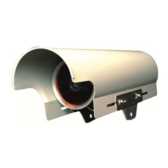
- Page 4 Camera User Guide Features Color or monochrome image sensors available • • Latest CCD sensing element and DSP technology • Electronic shutter and auto iris lens Auto focus with manual override • Camera Housing • • Sealed housing to IP67 specification •...
- Page 5 Camera User Guide Tools and Equipment Iteris Supplied Parts The following items come supplied with the Vantage Camera: Phoenix 3 pin Connector • Amphenol 31-321-1012 BNC connector (one per camera) • Video surge suppression (supplied with Edge2 processor) • 6’ (1.8meter) coax cable (supplied with Edge2 processor) •...
- Page 6 Camera User Guide • Bucket truck • Video monitor/patch cable • Vantage Lens Adjustment Module Volt/Ohmmeter •...
-
Page 7: Camera Installation
Camera User Guide 2. Camera Installation Camera Mounting The physical camera mounting is done using a camera bracket that is banded to the luminaire arm or can be mounted on the mast arm using a suitable extension bracket. One possible camera mounting location is up on the luminaire arm centered over the field of view, however, it is not always possible to use this mounting. - Page 8 Camera User Guide Approximately 12” (30cm) from the luminaire head Camera height should be at least 25’ (8m) above the roadway Mast Arm Mounting with Pelco Bracket If the luminaire arm is too short to center the camera over the field of view, especially on wide ...
-
Page 9: Camera Grounding
Camera User Guide Camera Video and Power Cable Installation This procedure describes how to install the coaxial and power cables between the camera mounting location and the traffic control cabinet. If you are installing multiple cameras, perform the procedure for each camera. The procedure is divided into the following parts: Running the cables Grounding the camera... - Page 10 Camera User Guide Camera Connections – RZ4 Advanced Remove the cap from the back of the camera by loosening the three screws. The system is provided with a simple “Quick-Click” connection for the power and a terminal block for the video output. Power Connection Strip the outer sheath from the power cable back 1”...
- Page 11 Camera User Guide Video Connector Loosen the coax cable clamp screws and remove clamp. Loosen the small cord grip. Strip Belden Coaxial Cable to length using Ideal Industries 45-521 coax stripping tool (Brown Cartridge). A = .328 B = .109in Strip .250in of inner conductor for insertion into the video connector. Feed cable through small cord grip and into video connector and tighten connector.
- Page 12 Camera User Guide Cabinet Connections Power Connection (Power Surge Panel) In the controller cabinet, AC power will need to be provided to each of the Vantage cameras. It is best to power the cameras from auxiliary breakers, to make sure that any damage to the camera power cables does not affect intersection cabinet power or controller operation.
- Page 13 If you have more than four cameras, you can double up (insert two wires) in two of the circuit breakers and two of the other (AC-) Neutral and Chassis Ground terminal blocks. Each circuit breaker is rated at two amps and a typical Iteris camera draws about 1/2 amp so this should not create any problems.
- Page 14 Camera User Guide Insert the male contact pin so that it butts up against the dielectric, crimp it in place using an Ideal Industries 30-483 coax crimping tool. Insert the connector body assembly over the dielectric and shielding and snap it into place. Make sure the center pin is completely seated in the connector body.
- Page 15 The specification sheet for the surge protection device is available in the "Technical Information" section of this manual. All surge protection must be approved by Iteris for use with the Vantage video detection systems. Failure to install surge protection, or using non-approved surge protection devices, will void the Vantage equipment warranties.
- Page 16 Camera User Guide 3. Camera Adjustment Field Of View Setup The image provided by the camera is critical to system performance. A good field of view (FOV) will ensure the best possible results from the system. The following should be kept in mind when adjusting the camera: •...
- Page 17 Camera User Guide Examples of Poor FOVs Four Lane Minimum Width Ideally, the camera should be zoomed in until a minimum of 4 lanes are visible, the horizon should not be included as a part of the field of view. The zones should be drawn within the lane lines and should be the size of a medium vehicle.
- Page 18 Camera User Guide Very Poor Mounting - Side Shoot, Camera Not Centered Proper Mounting Height – The camera should be mounted at approximately 30 feet for optimal system performance. For lower mountings, like a mast arm mount, a suitable camera extension bracket should be used to increase the camera mounting height to a more workable elevation.
- Page 19 Camera User Guide Maintain a Proper Camera Angle – The physical camera adjustments are done by adjusting the camera bracket mounting bolts to set the mechanical camera pan and tilt after the camera bracket has been mounted to the arm or pole. The camera should always be tilted slightly downward and should never be flat or beyond horizontal.
- Page 20 Camera User Guide The Camera Body Should Be Rotated Acceptable Camera Alignment Proper Camera Focus Adjustment – When you are sure that you can obtain the desired FOV, you will need to focus the camera using the LAM. Proper focus is crucial for optimal Vantage system detection performance. A camera that is out of focus can significantly reduce the Vantage systems ability to perform;...
- Page 21 Camera User Guide RZ4 Advanced Hook Up – Direct Connect RZ4 C and M Hook Up...
- Page 22 Camera User Guide Lens Adjustment Module (LAM) Field of View Adjustments There are two buttons on the LAM which allow you to control the zoom, wide angle (zoom out) or telephoto (Zoom in) and two buttons which allow you to control the focus adjustment. In addition there are two buttons marked ‘Set’...
-
Page 23: Troubleshooting Guide
Camera User Guide 4. Troubleshooting Guide Symptom A: No Video in Cabinet Verify that the coaxial cable is not touching the cabinet or signal pole. ii. Check for short circuit on the coax cable assembly using a multimeter. Set your multimeter to the ‘ohms’... - Page 24 Camera User Guide x. If these steps fail to remedy the situation, the LAM maybe bad and needs to be sent in for repair. Symptom C: Intermittent Video Video flickering on and off on the monitor along with the yellow LEDs on the processor. The yellow LEDs on the processor should be on solid.
- Page 25 Camera User Guide Symptom E: The video on the monitor looks too bright. Adjust the brightness and contrast controls on the monitor. ii. Check the video termination jumpers or dip switches on the processor. If the processor video inputs are set to HiZ then the picture will look bright. iii.
-
Page 26: Technical Information
Camera User Guide 6. Technical Information Belden Coaxial Cable Iteris requires the use of Belden 8281 coax cable for all installations. EDCO Surge Protection The Edco CX06-M, Surge Protective Device (SPD) implements three- stage hybrid technology. The SPD addresses over-voltage transients with a primary Gas Discharge Tube (GDT), and secondary Silicon Avalanche Diode (SAD) component. - Page 27 Camera User Guide Iteris requires the use of outdoor rated 16AWG 3 conductor cable for powering the Vector sensor. The cable should be UV, water and chemical resistant. Sample cables...
- Page 28 Camera User Guide...
- Page 29 0.5G, 3 axes, 5-30 Hz Dimensions (H x W L): Length 17”, Diameter 5” (Without Mounting Bracket) 432mm x 127mm Weight: 5.7 lbs (2.6 kg) Connection Type: BNC, 50/75 Ohm Multi-pole connection for power Iteris Vantage Camera Bracket - Iteris Part: CAMBRKT4...
-
Page 30: Product Support
The Universal Camera Bracket is designed to accommodate both horizontal and vertical structure mounting. The mounting bracket mates perfectly with Iteris's wired and wireless cameras and is constructed using high strength 6061 aluminum. For added protection, the assembly is gray powder coated. - Page 31 Vantage products. Please do not hesitate to contact us at: Toll free: (888) 254-5487 For more information on Iteris, as well as the products and services that we provide, visit our website at: www.iteris.com Iteris Resource Center This site contains additional training and technical support information covering the whole range of Vantage products.
- Page 32 1700 Carnegie Avenue Santa Ana, CA 92705 Phone: (949) 270-9400 Fax: (949) 270-9401...
Need help?
Do you have a question about the Vantage RZ4 Series and is the answer not in the manual?
Questions and answers