Table of Contents
Advertisement
Available languages
Available languages
ITA
Hydrosplit-M3
Calcolatore di energia Termica versione separata
MANUALE D'INSTALLAZIONE
Premessa
L'installazione deve essere eseguita esclusivamente da personale qualificato. Il produttore non si assume
alcuna responsabilità per installazioni errate o danni causati da terzi.
Avvertenze
Il calcolatore contiene batterie potenzialmente pericolose: maneggiare con cautela e non disperderle
nell'ambiente.
Hydrosplit M3 Manuale utente – User manual - v1.6.5_ITA_ENG
1
Advertisement
Table of Contents

Subscribe to Our Youtube Channel
Related Manuals for BMETERS Hydrosplit-M3


Summary of Contents for BMETERS Hydrosplit-M3
- Page 1 Hydrosplit-M3 Calcolatore di energia Termica versione separata MANUALE D’INSTALLAZIONE Premessa L’installazione deve essere eseguita esclusivamente da personale qualificato. Il produttore non si assume alcuna responsabilità per installazioni errate o danni causati da terzi. Avvertenze Il calcolatore contiene batterie potenzialmente pericolose: maneggiare con cautela e non disperderle nell’ambiente.
-
Page 2: Contenuto Confezione
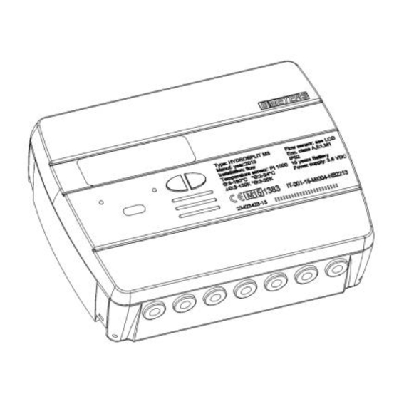
INTRODUZIONE Il modello Hydrosplit-M3 è un calcolatore elettronico separato che misura l’energia termica utilizzata negli impianti di riscaldamento e di raffrescamento. Il calcolatore consente di calcolare simultaneamente: - Energia termica in un circuito di riscaldamento/raffreddamento - Volume fino a 2 misuratori d’acqua calda/fredda sanitaria L’unità... -
Page 3: Installazione
INSTALLAZIONE UNITA’ DI CALCOLO Aprire l’unità di calcolo facendo leva sui quattro ganci ai lati [1] e rimuovere il coperchio [2]. Rimuovere la staffa di fissaggio alla base dell’unità di calcolo e fissarla alla parete. Sono previsti due tipi di fissaggio a muro: fissaggio diretto a muro mediante la staffa di fissaggio e seguente aggancio dell’unità... - Page 4 Applicare dunque la base sulla staffa e fissare con eventuali sigilli anti-rimozione. Dopo l’installazione, il collegamento, la configurazione e la messa in servizio, richiudere il coperchio e apporre i sigilli adesivi e/o piombature. INSTALLAZIONE SONDE TEMPERATURA Per l’installazione delle sonde di temperatura, consultare relativi manuale d’istruzioni. INSTALLAZIONE MISURATORI DI VOLUME Per l’installazione dei misuratori di volume, consultare relativi manuali d’istruzioni.
- Page 5 DESCRIZIONE MORSETTIERA Numeri Indicazione Descrizione Sonda temperatura mandata 1/5/6/2 Forward flow Sonda temperatura ritorno 3/7/8/4 Return flow Ingresso misuratore di portata 10/11/50 Flow IN Ingresso misuratore volume 1 51/52/53 C1 IN Ingresso misuratore volume 2 54/55/56 C2 IN Uscita impulsiva frigorie 57/58 Cold OUT Uscita impulsiva calorie...
- Page 6 - Collegare la sonda di mandata nei morsetti 5 e 6; - Collegare la sonda di ritorno nei morsetti 7 e 8. Avvertenza: per evitare eventuali errori nel calcolo dell’energia, rispettare la corrispondenza tra le sonde di temperatura di mandata e di ritorno e i rispettivi morsetti di collegamento. Utilizzare esclusivamente sonde di temperatura PT1000 conformi alla normativa EN1434-2 e certificate MID (2004/22/CE).
- Page 7 COLLEGAMENTO MISURATORI C1/C2IN Gli ingressi C1 IN (51, 52, 53) e C2 IN (54, 55, 56) sono dedicati ai misuratori di volume dell’acqua sanitaria calda e fredda. L’unità di calcolo è compatibile esclusivamente con misuratori di portata dotati di uscita impulsiva OC (open-collector) oppure OA (reed), con peso impulsivo litri/impulso (tassativamente compatibile al valore impostato sul calcolatore).
- Page 8 COLLEGAMENTO RETE M-BUS Gli ingressi MBUS (24 e 25) sono dedicati al collegamento del calcolatore con una rete M-Bus via cavo. Per il collegamento non è necessario rispettare la polarità, sebbene è buona norma mantenere le stesse polarità sull’intera rete cablata. Avvertenza: la rete M-Bus utilizza una tensione che può...
- Page 9 COLLEGAMENTO ALIMENTAZIONE AUX I morsetti 59 e 60 (Aux Power) sono dedicati al collegamento del calcolatore ad una rete elettrica esterna mediante l’uso alimentatore fornito come accessorio (3.6÷5 VDC, mA). in caso di collegamento alla rete elettrica, la batteria verrà impiegata come sorgente di alimentazione di backup.
- Page 10 INTERFACCE DI COMUNICAZIONE INTERFACCIA USCITA IMPULSIVA CALORIE/FRIGORIE Le uscite impulsive (Open Collector – 30V), collegate ad appositi totalizzatori compatibili, permettono la visualizzazione remota dei consumi delle calorie e delle frigorie. L’unità di calcolo è dotata di un’uscita impulsiva dedicata per le calorie (16, 17) e una dedicata per le frigorie (57, 58).
-
Page 11: Display E Pulsanti
DISPLAY E PULSANTI Il calcolatore è equipaggiato nella parte anteriore con un display a cristalli liquidi e due pulsanti (T1 e T2), utili alla configurazione dei parametri e alle letture. LEGENDA 1) Campo numerico a otto cifre; 2) Indice numerico ad una cifra (Livello menu); 3) Indice dati calorie;... - Page 12 4) Indice dati frigorie; 5) Indice dati circuiti 1-2 acqua calda/fredda sanitaria 6) Indice temperatura ritorno; 7) Indice temperatura mandata; 8) Segnalatore livello batteria; 9) Segnalatore anomalie; 10) Indice flussimetro circuito riscaldamento; 11) Indice dati M-Bus via cavo; 11+12) Indice dati M-Bus Wireless (predisposizione); 13) Indice storico;...
- Page 13 1) Il primo parametro da configurare è il peso impulsivo “k” del flussimetro dell’impianto di riscaldamento. Il valore è selezionabile mediante l’uso del tasto T1 tra: 0.1–0.25–1–2.5–10–25–100–250 L/imp Confermare il parametro scelto tenendo premuto il pulsante T2 per più di 3 secondi, passando così al parametro successivo.
- Page 14 5) Il quinto configurabile è l’abilitazione del contatto Antifrode per il contatore C1. Mediante il pulsante T1, procedere con l’abilitazione [1] o disabilitazione [0]. Confermare il parametro scelto tenendo premuto il pulsante T2 per più di 3 secondi, passando così al parametro successivo.
- Page 15 Confermare il parametro scelto tenendo premuto il pulsante T2 per più di 3 secondi, passando così al parametro successivo. 10) Il decimo parametro configurabile è il peso impulsivo “k” dell’uscita impulsiva OC delle frigorie (cold out). Il valore è selezionabile mediante l’uso del tasto T1 tra: 0 - 1 - 10 – 100 - 1000 kWh/imp Confermare il parametro scelto tenendo premuto il pulsante T2 per più...
- Page 16 14) Il quattordicesimo parametro configurabile è l’indirizzo secondario M-Bus via cavo (M-Bus) delle frigorie. Selezionare la cifra utilizzando il tasto T2 e cambiare il singolo numero con il tasto T1. Confermare il parametro scelto tenendo premuto il pulsante T2 per più di 3 secondi, passando così al parametro successivo.
- Page 17 1.3 Test del display – Tutti i segmenti spenti 1.4 Energia contabilizzata (frigorie) – valore cumulativo 1.5 Volume utile alla contabilizzazione (calorie) – valore cumulativo 1.6 Volume utile alla contabilizzazione (frigorie) – valore cumulativo 1.7 Volume totale (primo ingresso impulsivo addizionale) –...
- Page 18 2.5 Differenza di temperatura LIVELLO 3: IMPOSTAZIONI (VISUALIZZAZIONE) 3.1 Numero di serie 3.2 Versione Firmware 3.3 Versione Firmware comunicazione 3.4 Data attuale 3.5 Rapporto litri\impulso ingresso sensore di portata 3.6 Unità di misura (0= Mwh, 1= GJ) 3.7 Abilitazione allarme frode proveniente dal sensore di portata 3.8 Rapporto litri\impulso primo ingresso impulsivo addizionale...
- Page 19 3.11 Rapporto litri\impulso secondo ingresso impulsivo addizionale 3.12 Valore iniziale secondo contatore addizionale 3.13 Abilitazione allarme frode proveniente dal secondo ingresso impulsivo addizionale 3.14 Impostazione rapporto unità\energia per uscita impulsiva calorie 3.15 Impostazione rapporto unità\energia per uscita impulsiva frigorie 3.16 Indirizzo secondario MBUS calorie 3.17 Indirizzo primario MBUS calorie 3.18 Indirizzo secondario MBUS frigorie 3.19 Indirizzo primario MBUS frigorie...
- Page 20 LIVELLO 3: IMPOSTAZIONI (CONFIGURAZIONE) Il settaggio delle impostazioni può essere abilitato tramite pressione di T2 per 3 secondi durante la visualizzazione di una delle voci del livello 3 3s.1 Richiesta password per abilitazione settaggio parametri 3s.2 Impostazione rapport litri\impulso (sensore di portata) 3s.3 Abilitazione contatto di rilevamento frode (sensore di portata) 3s.4 Impostazione rapport litri\impulso (primo...
- Page 21 3s.11 Impostazione rapporto unità\impulso per uscita impulsiva (frigorie) 3s.12 Impostazione indirizzo secondario MBUS (calorie) 3s.13 Impostazione indirizzo primario MBUS (calorie) 3s.14 Impostazione indirizzo secondario MBUS (frigorie) 3s.15 Impostazione indirizzo primario MBUS (frigorie) 3s.16 Salvataggio settaggi e uscita 1= salva parametri ed esci, 0= non uscire Hydrosplit M3 Manuale utente –...
- Page 22 LIVELLO 4: DATI DEL GIORNO DI MEMORIZZAZIONE 4.1 Giorno di memorizzazione 4.2 Energia contabilizzata (calorie) – valore cumulato al giorno di memorizzazione 4.3 Energia contabilizzata (frigorie) – valore cumulato al giorno di memorizzazione 4.4 Volume (primo ingresso impulsivo addizionale) – valore cumulato al giorno di memorizzazione (opzionale) 4.5 Volume (secondo ingresso impulsivo addizionale) –...
- Page 23 5.3 Data di memorizzazione dello storico (fino a 26 valori possibili, salvataggio alla fine del mese) 5.3.1 Energia contabilizzata (calorie) – valore cumulato al giorno di memorizzazione dello storico 5.3.2 Energia contabilizzata (frigorie) – valore cumulato al giorno di memorizzazione dello storico 5.3.3 Volume (secondo ingresso impulsivo addizionale) –...
-
Page 24: Messa In Servizio
MESSA IN SERVIZIO Premessa: le procedure indicate in questo paragrafo vanno eseguite solo dopo aver completato le fasi d’installazione, terminato i collegamenti ed eseguito le prove funzionali dell’impianto di acqua calda e fredda sanitaria e di riscaldamento / raffrescamento. Avvertenza: dopo che l’unità ha contabilizzato energia e volumi, alcuni dei parametri configurabili non saranno più... - Page 25 Di seguito viene riportato l’elenco di tutti i codici di errore: Errore Descrizione Prescrizione Note Err101 Taglio cavo di almeno una delle Verificare l’integrità e il L’allarme viene resettato alla sonde; collegamento delle sonde di risoluzione del problema Almeno una delle sonde non presente temperatura.
- Page 26 BATTERIA E PROCEDURE PER LA SOSTITUZIONE L’unità di calcolo tiene costantemente monitorato lo stato della batteria (durata media: 10 anni) e segnala l’imminente scaricamento mostrando a display l’icona . La segnalazione avviene un anno prima del totale scaricamento. Per la sostituzione, contattare il produttore. Avvertenza: L’unità...
- Page 27 DATI TECNICI UNITA’ DI CALCOLO Modello Hydrosplit M3 Alimentazione -A batteria -Alimentazione elettrica (opzionale 3.6 ÷ 5 VDC, 300 mA): in questo caso la batteria viene impiegata come alimentazione di riserva Tipo batteria Li-SoCl2 Litio-Cloruro di Tionile, 3,6V “size D” 20Ah Durata batteria 10 anni +1 Range temperature utilizzo...
- Page 28 Condizioni operative conteggio Riscaldamento: ΔΘ≥1K e temperatura del liquido ≥5°C (condizioni di abilitazione del conteggio) Raffrescamento: ΔΘ≤0.2K e temperatura del liquido ≤24°C Potenza Massima misurabile 650 kW Portata massima misurabile 2000 m3\h Display LCD, 8 cifre + icone Unità di misura MWh (standard), GJ (opzionale) Sonde di temperatura Pt1000 (a due fili)
- Page 29 FUNZIONAMENTO AL DI FUORI DEL LIMITI DICHIARATI Si raccomanda di accertarsi che le condizioni di misura siano entro i limiti di certificazione esposti. L’unità non disabilita l’operatività al di fuori di tali intervalli, il suo utilizzo non è coperto da certificazione se le condizioni di misura non sono conformi alle condizioni di validità...
- Page 30 Hydrosplit M3 Manuale utente – User manual - v1.6.5_ITA_ENG...
- Page 31 Hydrosplit-M3 Heat/cooling calculator, separated version USER MANUAL Premise The installation must be carried out by qualified personnel only. The manufacturer doesn’t assume any responsibility for improper installation or damages caused by third parties. Warning The calculator contains potentially dangerous batteries: handle carefully and do not dump in the environment.
-
Page 32: Package Contents
INTRODUCTION The model Hydrosplit-M3 is a separate electronic calculator that measures the thermal energy used in the heating and cooling systems. The calculator allows the simultaneous calculation of: - Thermal energy in a heating/cooling system. - Volume up to 2 flow meters for hot and cold sanitary water. -
Page 33: Installation
INSTALLATION CALCULATION UNIT Open the calculation unit by leveraging on the four hooks on the sides [1] and remove the cover [2]. Remove the bracket behind of the calculation unit and secure it to the wall. There are two types of wall mounting allowed: direct wall mounting by using the mounting bracket and the following hooking of the calculation unit on the same bracket;... -
Page 34: Components Connections
Then apply the basis on the bracket and secure it with any anti-removal seals. After the installation, connection, configuration and commissioning, close the cover and apply adhesives and / or lead sealings. TEMPERATURE SENSORS INSTALLATION For the temperature sensors installation, see related manual. FLOW METERS INSTALLATION For the flow meters installation, see related manual. -
Page 35: Temperature Sensors Connection
TERMINAL BOARD DESCRIPTION Numbers Indication Description Inlet temperature sensor 1/5/6/2 Forward flow return temperature sensor 3/7/8/4 Return flow Flow meter input 10/11/50 Flow IN Volume meter input 1 51/52/53 C1 IN Volume meter input 1 54/55/56 C2 IN Cooling pulse output 57/58 Cold OUT Heating pulse output... -
Page 36: Flow Meter Connection
return temperature sensors and the respective terminals. Use PT1000 temperature sensors only, EN1434- 2 MID (2004/22/CE) approved. FLOW METER CONNECTION Connect the flow meter for thermal energy metering in the pulse input “flow in” (10,11,50). The calculation unit is compatible with flowmeters with pulse output OC (open collector) or OA (reed), with pulse value “liters/pulse”... -
Page 37: Pulse Output Connections
Warning: when using flow meters with Open-Collector (OC) output, it is necessary to follow the correct connection polarity. PULSE OUTPUT CONNECTIONS The calculator is equipped with two Open-Collector pulse outputs (30V): - refrigeration units output: cold OUT (57, 58) - heating units output: hot OUT (16, 17) These outputs can be connected to a compatible totalizer or to a signal converter. - Page 38 For the connection is not necessary to respect the polarity, although it is advisable to keep the same polarity on the entire cable network. Warning: the M-Bus network is using voltage that can damage the device when applied to terminals dedicated to other functions, so be careful when connecting to this interface.
-
Page 39: Communication Interfaces
MASUREMENTS REPRESENTATION The representation format of the measurements of the energy/power and volume/flow rate is determined basing on the pulse value "k" set up directly on the configuration. The pulse value also determines the maximum power that, in accordance with standard EN1434-2, must - k<10: representation of energy consumption with 5 integers and 3 decimal 00000,000 MWh (GJ) - 10<k<100: representation of energy consumption with 6 integers and 2 decimal 000000.00 MWh (GJ) - k≥100: representation of energy consumption with 7 integers and one decimal 0000000.0 MWh (GJ) -
Page 40: Display And Buttons
DISPLAY AND BUTTONS The calculator is equipped in the front with a liquid crystal display and two buttons (T1 and T2), useful for the configuration of the parameters and for the readings. 1) Eight-digit numeric field; 2) Single-digit numeric index (menu level); 3) Heating data index;... -
Page 41: Programming Menu
6) Return flow temperature index; 7) Inlet flow temperature index; 8) Battery level indicator; 9) Faults indicator; 10) Heating system flowmeter index; 11) Wired M-Bus data index; 11+12) Wireless M-Bus data index (predisposition); 13) Historical data index; 14) Pulse value index (k); 15) Measurement unit index;... - Page 42 The value can be selected by using the button T1: 0.1–0.25–1–2.5–10–25–100–250 L/imp Confirm the selected parameter by holding the T2 button for more than 3 seconds, thus moving to the next parameter. Warning: the pulse value “k” of the heating system flowmeter is settable only once. Once the configuration is confirmed, this parameter is no longer editable.
- Page 43 5) The fifth parameter that has be configured is the enabling/disabling of the anti-tampering contact of the C1 cold/hot water meter. By using the T1 button, proceed with the enabling [1] or disabling [0]. Confirm the selected parameter by holding the T2 button for more than 3 seconds, thus moving to the next parameter.
- Page 44 Confirm the selected parameter by holding the T2 button for more than 3 seconds, thus moving to the next parameter. 10) The tenth parameter that has be configured is the pulse value "k" of the OC pulse cooling output (cold out).
- Page 45 Confirm the selected parameter by holding the T2 button for more than 3 seconds, thus moving to the next parameter. 14) The fourteenth parameter that has be configured is the primary address of the Wired M-Bus (M-Bus) of the cooling data. Select the digit using the T2 button and change the single numbers with the T1 button. Confirm the selected parameter by holding the T2 button for more than 3 seconds, thus moving to the next parameter.
- Page 46 1.3 Display test – All segments off 1.4 Accounted energy (cooling) – cumulative value 1.5 Volume useful for the accounting (heating) – cumulative value 1.6 Volume useful for the accounting (cooling) – cumulative value 1.7 Total volume (first pulse input - C1) – cumulative value (optional) 1.8 Total volume (second pulse input –...
- Page 47 2.5 Temperature difference LEVEL 3: SETTINGS (DISPLAYING ONLY) 3.1 Serial number 3.2 Firmware version 3.3 Communication Firmware version 3.4 Current Date 3.5 Liters/pulse value for input flow sensor (flow in) 3.6 Measurement unit (0= Mwh, 1= GJ) 3.7 Input flow sensor (Flow in) anti-tampering activated/deactivated 3.8 Liters/pulse value for first input flow meter (C1)
- Page 48 3.10 Input flow meter (C1) anti-tampering activated/deactivated 3.11 Liters/pulse value for second input flow meter (C2) 3.12 Starting value second input flow meter (C2) 3.13 Input flow meter (C2) anti-tampering activated/deactivated 3.14 Liters/pulse value for heating pulse output (Hot out) 3.15 Liters/pulse value for cooling pulse output (Cold out) 3.16 M-Bus Secondary address (Heating)
- Page 49 LEVEL 3: SETTINGS (CONFIGURATION) The setting of the parameters can be enabled by pressing T2 for 3 seconds while viewing one of the points of the level 3. 3s.1 Password request to enable parameters setting 3s.2 Liters/pulse value setting for input flow sensor (flow in) 3s.3 Input flow sensor (Flow in) anti-tampering activated/deactivated setting...
- Page 50 3s.11 Liters/pulse value for cooling pulse output (Cold out) 3s.12 M-Bus Secondary address setting (Heating) 3s.13 M-Bus Primary address setting (Heating) 3s.14 M-Bus Secondary address setting (Cooling) 3s.15 M-Bus Primary address setting (Cooling) 3s.16 Saving parameters settings and exit 1 = save and exit, 0 = don’t exit LEVEL 4: MEMORY DAY DATA 4.1 Memory Day 4.2 Accounted Energy (heating) –...
- Page 51 4.5 Accounted Volume (C2) – accounted volume at memory day (optional) Memory day setting: View any of the points in the level 4 Press and hold T2 button for 3 seconds. The setting screen will be displayed. Enter the desired date in the gg.mm format (T1 - digit increase, T2 - selection digit). Confirm the setting by pressing and holding the T2 button for 3 seconds.
- Page 52 5.3.4 Accounted Volume (C2) – accounted volume at historical memory day (optional) LEVEL 6: ERRORS AND FAULTS 5.1 Functioning hours during error 5.2 Active error list 5.3 Number of accesses with installer password 5.3.1 Date of last modified setup parameters COMMISSIONING Premise: the procedures explained in this paragraph must be carried out only after the conclusion of the installation phases, the connection procedures and after the testing of the hot/cold water and...
-
Page 53: Errors And Faults
COMMISSIONING PROCEDURE 1) Ensure that the electrical wirings are carried out correctly; 2) Check in the level 3 that all parameters are correctly set on the calculator (especially the pulse value for the flow sensor –flow in-); 3) Verify that the flowmeters and volume meters, the temperature sensors etc. are installed correctly. (always refer to the installation manuals specific to every product) 4) Start the heating system: - Check if the registered values are coherent (inlet/return temp.) - Page 54 Here is a list of all the error codes: Error Description Prescription Notes Err101 One of the two temperature sensor Check the integrity and the The alarm automatically cables is cut; connection of the temperature resets when the issue is At least one cable is disconnected sensor cables.
- Page 55 BATTERY AND REPLACEMENT PROCEDURES The calculation unit constantly checks the battery status (average lifetime: 10 years) and signals the imminent discharge showing the icon on the display. The signal will be shown one year before the complete discharge. For the replacement, contact the manufacturer. Warning: the calculation unit is equipped with non-rechargeable batteries, that can be dangerous when used improperly.
- Page 56 CALCULATION UNIT DATA SHEET Model Hydrosplit M3 Power supply -Battery supply -Electrical supply (optional, 3.6 ÷ 5 VDC, 300 mA): in this case, the battery will be used as backup power supply) Battery type Li-SoCl2 Lithium-thionyl chloride, 3,6V “size D” 20Ah Battery Life 10 years +1 Operating temperature range...
- Page 57 Operative counting conditions Heating: ΔΘ≥1K and fluid temperature ≥5°C (accounting enabling conditions) Cooling: ΔΘ≤0.2K and fluid temperature ≤24°C Maximum measurable power 650 kW Maximum measurable flowrate 2000 m3\h Display LCD, 8 digits + icons Measurement unit MWh (standard), GJ (optional) Temperature sensors Pt1000 (two-wired) Cable length...
- Page 58 FUNCTIONING BEYOND THE LIMITATIONS DECLARED It is recommended to ensure that the measurement conditions are within the exposed limits of certification. The unit doesn’t disable the functioning outside these ranges, its use is not covered by the certification if the measurement conditions don’t meet the certification validity conditions. Regarding the flow measurement conditions of the flow sensor connected to the calculator, always respect of the flow rates recommended in the table here below depending on the factor of the flow sensor.
- Page 59 Hydrosplit M3 Manuale utente – User manual - v1.6.5_ITA_ENG...
Need help?
Do you have a question about the Hydrosplit-M3 and is the answer not in the manual?
Questions and answers