
Subscribe to Our Youtube Channel
Related Manuals for Alpha GSM Lift Watch 3G voice

Summary of Contents for Alpha GSM Lift Watch 3G voice
- Page 1 GSM LIFT COMMUNICATION SYSTEM GSM Lift Watch 3G Voice Installation and programming manual v2.0...
-
Page 2: Basic Technical Parameters
The GSM lift watch is designed for emergency call from lift cabin to first aid ( service department, security, etc..). The unit is developed up directive EN 81-28 / EN 81-70. Basic technical parameters: Power supply 8 to 30V ss, 50 to 500mA (up operation) Integrated ACU Li-Ion 2000 mAh - cca 12h of operation in stand by... - Page 3 the call is made regardless of the blocking (new EN 81- Indication of establishing as same as running call. Indication of other device status by switches for optical signalization and acoustically (voice messages) – possibility record own messages Relay mode for lift blocking during lift failure or GLWV issue (GSM network logging, correct ACU voltage , not blocking emergency call button) ...
- Page 4 MASTER and TEST numbers exchange o GSM network status o SMS with AT commands for GSM module Sending of adjustable SMS when input status is changed – individual SMS for both inputs status SMS when button is blocked ...
- Page 5 Emergency call from lift cabin By button press you activate the device (adjustable button pressing time for activation). It is close port I1 on ReMic (for lighting up yellow indication light – activation/call establish), You hear message „number dialing, wait“ and the unit progresivelly dials phone numbers saved under names MASTER1 to MASTER7 on inserted SIM card.
-
Page 6: Blocking Of Emergency Call
Waiting for dialing next number 20 s After button press for time longer than 3 sec is closed port I1, it is play message „number dialing, wait “, it is dialing number saved under MASTER1. Nobody picks up. The 20s after number dial is calling ended. -
Page 7: Back Calling
Example2 Blocking is connected to door contact. The door are opened- port is short circuited Setting: Activation time of port short circuit 3s Blocking survilance after port is deactivated 65s (time of longest lift run Lift doors are closing, lift starts running, call is blocked . The lift stops, the doors are not opening. - Page 8 message „Call is ended“. Phone numbers might be the same in both sets ( MASTER and TEST). In the same time might be beside or instead testing call tested local acoustic connection (GLW – cables – ReMic speaker – ReMic microphone – cables GLW). During test is activated message „Sound test –...
-
Page 9: Status Information (Sms)
Status information (SMS) Status informations GLW V sending by different SMS: TEST/STATUS: SMS via previous capture. Except test could be activated also by SMS „READ STATUS“ (more about in capture about SMS). When is setup Acoustic test then is performed always before SMS sending. ... - Page 10 includes word „oper“ then all SMS received from this number will be forwarded automatically to TEST 8 number. Contents of all SMS (text of all SMS) might be edited up desire by PC programm for GLWVset (via later). Emergency alarm mode At this setting is activated „emergency“...
- Page 11 Relay The Relays might be programmed into 7 different modes: Close/open is control by SMS (for example. „SET REL1 ON“) Close/open is control by „emergency“ status (via previous capture) „Camera“ mode when relay close after call is picking up ...
- Page 12 SIM PIN When you desire to operate the unit with SIM card without PIN then before inserting SIM card into unit switch off the PIN. (in any mobile phone) When you desire to operate the unit with SIM card with PIN you have to setup PIN at any mobile phone to 0000.
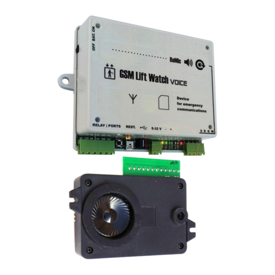
- Page 13 Parts of GSM Lift Watch: Basic unit (GLWV) Speaker module (ReMic)
- Page 14 Switch for backup ACU Loudness setting Sim card LED indication Screws and PSU LED USB connector USB connector GSM antenna RESET button Ports screw terminal ReMic screw terminal Relay screw terminal (SRGM)
-
Page 15: Ports (In1, In2)And Relay Screw Terminal
Ports (IN1, IN2)and relay screw terminal Blocking input IN2 (short circuit to ground) Shared screw - ground input IN1 Relay contact screw (in stand by open - NO) Shared relay contacts screw (COM) Contact relay screw (in stand by closed - NC) LED indicators PWR - power GSM –... -
Page 16: Screw Terminal For Remic (Srgm)
Screw terminal for ReMic (SRGM) Screws for connection to ReMic module in lift cabin – connect same marked screws M – microphone G – ground R – speaker S - signaling Screw terminal of speaker modul ReMicA (ReMic) Jumper current limiting of switch (see example examples) Screws of indicator switch I1 Screws of indicator switch I2... - Page 17 Installation: Fix the acoustic unit (ReMic) behind table panel in the lift cabin. To approach good voice quality we recommend place the REMIC unit in level of human head. At front of MIC must be hole in table button panel otherwise there will be bad voice quality from lift cabin! speaker and MIC are installed toward to lift...
- Page 18 Fix the GSM part of unit either on lift cabin or in machine room. You have to select right place regards to GSM signal strength.Lift cabin installation is easier (it is not necessary cable from lift cabin to machine room and due this is avoid of interference).
-
Page 19: Operation Start
Screw up antenna cable connector. The antenna position must not be in space surronding by metal (metal shafts etc..) It caused reduction of GSM signal. When you connect magnetic antenna please put it to some bigger iron subject. which enables to create bigger GSM signal power. It is also important to place antenna out of basic unit to not interference the voice channel by GSM radiation ( you know it from radio in car) - Page 20 Blue LED lights up (PWR) as same as RED LED on speaker modul (ReMic). Until cca 5 seconds you hear beeps from REMIC speaker Until cca 25 seconds will start flashing yellow LED (GSM) Until cca cca 1 minute (up GSM network status) you hear message „Unit is in stand by mode“.
-
Page 21: Faq During Operation Start
up green LED „connect“ (CON) and „Emergency lift call.“message is played. Loudness might be adjusted by controller on GLWV (thin screw driver!). By configuration PC programm or by SMS you can setup loudness as same as Microphone sensitivity (mostly is not required any adjustment). Whe is loudness too high you can get different acoustic troubles like acoustic shock, etc... - Page 22 Blue LED lights up LED (PWR), yellow LED (GSM) flashing, „ERROR“ message is played and yellow LED (GSM) light up permanently. GLWV is not capable read inserted SIM card. Most propably SIM has PIN activated but it is not „0000“ or does not correspond to unique PIN of the unit ( GSM modul) (via capture SIM PIN) Blue LED (PWR) lights up, yellow LED (GSM) is flashing,...
- Page 23 You hear different acoustic shocks and feedbacks in the call (pwhistling, ECHO etc..) Too big amplification in whole system (microphone of called party phone – speaker in lift cabin – acoustic parameters of lift cabin – microphone in lift cabin – speaker of called party phone).
-
Page 24: System Programming
System programming There are 3 ways of System programming: 1. By savings appropriate numbers (MASTERx eventually TESTx, eventually PARGLWV and PARRL1) to SIM card by mobile phone. 2. Remotely by SMS messages. On the SIM card inserted in the unit must be already programmed number from which we send SMS like TESTx (x is number1 to 8). - Page 25 (TEST). The line after space it means numbers which are not dialed by unit might be multiple (on the SIM card might be saved 6 numbers under name MASTER4). It means that amount of numbers allowed for incoming calls or programming are limited just by SIM card capacity.
- Page 26 Numbers and names saved on SIM card meaning name operation MASTER1 - first number which is call by GLWV after emergency call activation. When GLWV should emergency functionality this number must be saved on the SIM card. - this number is allowed make incoming calls MASTER2 - when this number is saved the GLWV call him when MASTER1 number is unreachable, busy or doesn’t pick...
- Page 27 - this number is allowed make remote SMS configuration TEST3 - when this number is saved the GLWV call him when TEST2 number is unreachable, busy or doesn’t pick up call a long time - this number is allowed make incoming calls - this number is allowed make remote SMS configuration TEST4 - when this number is saved the GLWV call him when...
- Page 28 PORTOPEN -into this number is sends SMS - ,PORT OPEN‘ when IN1 port is open - firmware version in GLWV - just info don’t change! SERVICES - date of last service check and number of checks (mode “Servis OK”) - just info – don’t change! PARGLWV - GLWV parameters A#B#C#D#E#F#GG#H#I#J...
- Page 29 6 – „running” mode – relay closed, when GLWV operates (voltage, logged in GSM network) CC – closing time [00-99]s D – [1] – reserved necessary fill by 1 Remote setting and control by SMS They are accepted just SMS sends from registered numbers on the SIM as TEST1 to TEST8.
- Page 30 WRITE PAR TPERIOD:3 WRITE PAR BLOCK:09 GLWV sends back SMS where is copied inserted command at beginning. Then follows colon after which is result of command (for example OK when name and phone number is saved) Commands table for SMS Command ( SMS) Function Def.
- Page 31 WRITE PAR WBLOCK:x time x sec. Of IN2 port closing necessary for blocking start [x=0-9]s WRITE PAR BLOCK:xx Blocking duration xx sec. After IN2 port is opened [xx=00-99]s WRITE PAR WACT:x Time x sec. Of button press to make emergency call [x=0-9]s WRITE PAR WCALL:xx time...
- Page 32 CAL AT+CPBR=x Identification of number saved under position x CAL AT+CCLK=“<time>“ Time setting in GLWV on <time> format <time>= yy/MM/dd,hh:mm:ss±zz yy – year (00-99) MM – month (01-12) dd – day (01-31) hh – hours (00-23) mm – minutes (00 – 59) ss –...
- Page 33 SMS example for setting GLWV parameters: WRITE PAR: VOLIN:1 VOLOUT:4 BLOCK:60 RL1MOD : 1 GLWVanswer: WRITE PAR: VOLIN:1 BLOCK:60 Next examples: Read of service visits number and date of last one: READ SERVICES GLWV answer: READ SERVICES:14*09*23#3 Where 14*09*23 is date 23.9.2014 and 3 is number of visits Relay close attempt in incorrect mode (different from determined for control by SMS) SET REL1 ON...
- Page 34 BLOCK: 0 REL: OFF ECALL:- AKUSTIC: PASS Single parameter saving – setting of waiting time for dialing next number 30 seconds: WRITE PAR WCALL:30 GLWV answer: WRITE PAR: WCALL:30...
-
Page 35: Computer ( Pc) Programming
Computer ( PC) programming 1. To preselected directory in PC (for example GLWV) copy from CD programm GLWVset. The programm is „portable“ – doesn't need installation. In case of need you will be add to same directory sounds files address etc.. - Page 36 mode „ON“ „ON“ mode is identify by switch in position ON To programm parameters stop GLWV operation(programming mode) by click to button. Programm sends signal to GLWV and wait for answer (shows bargraf – via picture) After a while (GLWV checks signal every 30 seconds) will GLWV switch –...
- Page 37 After click to „Support“ button is possible monitor GLWV operation (when operation is not stop by button „ON/OFF“) Saving of report (log) from monitor to file (for service purposes – report sending)
- Page 38 Programming mode (position OFF) GLWV is signalling programming mode by message „Unit in stand by mode“ and permanent light of yellow LED (GSM). Programm indicates mode by switch in position „OFF“. All parameters are automatically recorded from GLWV to the programm. „EMERGENCY“...
- Page 39 Folder „SERVICE It is designed for service call parameters programming Period of TEST function activation Movement of TESTs start from midnight Test type setting Number for sending status SMS Waiting for connection before dialing next number in order. Overtake from EMERGENCY Field to programm up 7 phone numbers of service call...
- Page 40 Phone Book folder Phone book on the SIM – checking numbers on the SIM – for example: GSM operator, service status (SERVICE) etc…. Name position Phone number position Add line over line with cursor Erase line with cursor Search for inserted name...
- Page 41 „Ports“ folder Relay mode setting Numbers where are send SMS when IN1 port is open and closed When number is not filled SMS is not send Information about mode which influence using type of IN1 port(SMS) Voltage on limit level for decision acceptable/low voltage.
- Page 42 „Support“ folder In „ON“ mode is designed for operation monitor (via „ON“ mode) In„OFF“ mode is designed for upgrade fw, adjustment voice messages and SMS contents. CAUTION! Not expert manipulation might caused unfunctionality of GLWV which is not responsibility of producer. Commands or files list which will be recorded to GLWV (manually editable)
- Page 43 Examples We recommend copy of command examples from CD to directory with PC configuration programm. Voice messages substitution by other language from sent file. 1. open the zip file (even with directory) into directory where you have PC configuration programm GLWVset. 2.
- Page 44 Voice message substitution by own messages with miss message „emergency communicator of lift“ 1. Zip file VoiceMessages from examples open (even with directory) to directory in which you have PC configuration programm GLWVset 2. Files substitute by yours (except file ecall.aiff) in the same format (aiff, PCM, 8kHz, mono, 8 bit) –...
- Page 45 2. Create here your file ecall.aiff (aiff, PCM, 8kHz, mono, 8 bits) with your own identifying record. As base you might use current ecall.aiff. 3. Click on button „Load List“ and in directory select file „EcallMessages.ifo“ – will be shown list of sound messages (here just one –...
- Page 46 Return from programming mode to stand by mode „ON“ (again start of GLWV) When all settings is done by press button Save do GDI. GLWV will start again by switching to mode „ON“ – click on button. Programm will send signal to GLWV and wait for answer (monitor by bargraf –...
- Page 47 Amendments: GLWV LED signalling Permanent light Blue LED Permanent light – weak lighting (PWR) Not light Short flashing with period 2 sec. 1 to 5x short flash ▌▌▌ ▌▌▌ Yellow LED ...
-
Page 48: Glwv Voice Messages And Tones
GLWV voice messages and tones Besides ordinary tones and signals of GSM communication (ringing tone, busy tone, different operator messages), has GLWV own operation signals. Trill up medium height tone High tone once after number dialing ... - Page 49 Message block.wav: „Emergency call is blocked. Try again later please.“ Message ecall.wav: - „Emergency communicator of lift.“ E Message endcall.wav: „Call is hanged up.“ E Message error.wav: „ERROR“ Message nocall.wav: „Connection failed. Try again TE later please.“...
-
Page 50: Inserting Of Acu
GLWV with backup ACU When you have GLWV with backup ACU already integrated before installing and operation start check if ACU switch is in down position (off). Do not store unit with ACU when ACUswitch is not in down position! By selfdischarging might be ACU destroyed without warranty. - Page 51 When ACU polarity is incorrect flash or light permanently red LED. When all is correct then connect power supply and move switch to up position. – By this connect ACU into system. Test ACU operation by disconnecting of main power supply. We not provide warranty for damages caused by incorrect progress of ACU connection.
- Page 52 Simplest connection ReMicA without optical signaling signaling in lift cabin by voice only, power supply from lift system. Emergency button 8-32V...
- Page 53 Basic connection ReMicA with signaling bulbs power supply from lift system. Jumpers closed +/- 12-24V +/- 12-24V Emergency button ReMicA 8-32V...
- Page 54 Basic connection ReMicA with signaling LEDs power supply from lift system. 12-24V Jumpers opened 12-24V Emergency button ReMic 8-32V...
- Page 55 Basic connection ReMicL with controling of signaling logic inputs table in the cab (to ground) power supply from lift system. TABLE Jumpers closed Emergency button ReMicA 8-32V...
- Page 56 Basic connection ReMicL with signaling LEDs power supply from lift system. (ReMicL is intended only for direct LED connection) Upper jumpers closed in trio Emergency button ReMicL 8-32V...
- Page 57 Basic connection with main power supply +/- 12-24V +/- 12-24V Emergency button ReMicA Main PSU 230 Vac / 12Vdc...
- Page 58 Connection example with external ACU and charger +/- 12-24V +/- 12-24V Emergency button ReMicA Pb ACU 12V/7 Ah Main Pb ACU charger 12V/700mA...
- Page 59 Connection example for lift cabin – machine room (PREPOJ) communication Lift cabin communication - + 12-24V ReMicA/ReMicL PREPOJ Machine room communication 8-32V...
- Page 60 Connection example for communication lift cabin – shaft – machine room (totally possible connect 3pcs ReMic) Lift cabin communication ReMicA/L - + 12-24V Lift shaft communication PREPOJ 2x ReMicB Machine room communication 8-32V...
- Page 61 Connection examples of next call blocking in relay mode „emergency“ Door contact Door open - closed Connection example of activation by galvanically isolated screws of switch 12V ReMic – connection to bell or siren.
- Page 62 Siren connection example in relay mode „button“ (Relay closed during button press) 12-24V (according siren) Connection example of „servis“ button with pilot light of „confirmation“ (Pilot light will lights up when GLWV receive „servis“ button press and send SMS) button“servis” 12-24V (according pilot light)
- Page 63 Alphatech spol. s r.o. Jeremenkova 88 140 00 Praha 4 tel. +42 0 272 103 335, fax. +42 0 272 103 334 e-mail: info@alphatech.cz internet: http://www.alphatech.cz naše souřadnice GPS (WGS 84) N 500235.5 E 142542.0 9.1.2018...
Need help?
Do you have a question about the GSM Lift Watch 3G voice and is the answer not in the manual?
Questions and answers