Table of Contents
Advertisement
Advertisement
Table of Contents

Related Manuals for Cattron-Theimeg LRC-L1


Summary of Contents for Cattron-Theimeg LRC-L1
- Page 1 User Manual Radio Remote Control LRC-L1 Transmitter Unit...
- Page 2 This technical document or parts thereof may not be reprinted or copied – except for own use for the operation of the radio transmitter system – without the written permission of Cattron-Theimeg Europe GmbH & Co. KG. It may not be made accessible to a third party. The copying of the described radio remote control system is not permitted.
-
Page 3: Table Of Contents
User Manual LRC-L1 Table of Contents Page 1 Introduction ..........................4 2 Safety Instructions ........................5 2.1 Used Symbols and Definitions for Warnings....................5 2.2 General Information on Safety ........................5 2.3 Use for Intended Purpose ..........................6 2.4 Improper Use..............................6 2.5 Safety Instructions for Assembly/Disassembly ....................6 2.6 Operation of Radio Transmitter System Components with Identical System Address ........6... -
Page 4: Introduction
This manual includes general information concerning the operation of the radio remote control transmitter series CattronControl LRC-L1. The information is of general nature and does not include system-specific data. System-specific data is provided in the technical documentation accompanying the delivery of the system. -
Page 5: Safety Instructions
User Manual LRC-L1 2 Safety Instructions 2.1 Used Symbols and Definitions for Warnings Warning against hazardous situation Warning against electrical voltage Useful information Calls attention to a dangerous situation with high risk, severe injuries or death DANGER possible. WARNING Calls attention to a situation with medium risk, severe injuries possible. -
Page 6: Use For Intended Purpose
User Manual LRC-L1 2.3 Use for Intended Purpose The product must only be used in a technically perfect condition, by instructed personnel and subject to the compliance with the applicable safety and accident prevention regulations. The product is electrical equipment for use at the rated voltage shown on the type plate. A use for the intended purpose also requires a compliance with the contents of this User Manual, particularly the therein described requirements and instructions. -
Page 7: General
User Manual LRC-L1 3 General With a transmitter and a matching receiver unit a device such as a crane, a machine or a vehicle can be radio controlled, thus avoiding the need for a wired connection between the human interface and the device to be controlled. -
Page 8: Transmitter Unit
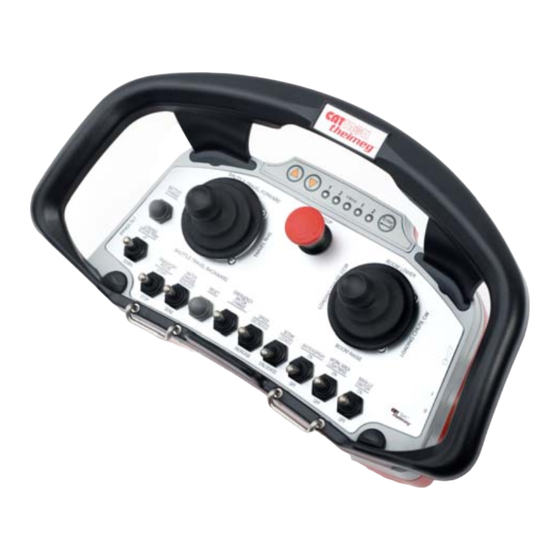
4 Transmitter Unit 4.1 General The LRC-L1 transmitter is a versatile transmitter unit that can be highly customized to meet the operational requirements of many different applications. For this, a variety of control elements (joysticks, paddles, push buttons, switches etc.) is available to tailor a transmitter layout for the individual application. -
Page 9: Before Turning On
User Manual LRC-L1 4.3 Before turning on ⇒ Verify that the TransKey (black) is placed in the TransKey hollow inside the battery compartment ⇒ Insert a fully charged battery NOTE Batteries are shipped uncharged! 4.4 Turning the transmitter on (Standard) ⇒... -
Page 10: Automatic Turn-Off
User Manual LRC-L1 4.8 Automatic Turn-off The transmitter turns off automatically when the following events occur: • Battery discharge protection (battery low) • Internal failure (hardware or software) 4.9 Status LED The status LED indicates the operation mode and error messages. -
Page 11: Battery & Battery Charger
The charger must only be operated in dry indoor spaces. Do not use the charger if the housing or mains plug is damaged! Contact the customer service department of Cattron-Theimeg Europe GmbH & Co. KG. 5.2 Charger Status Indication... -
Page 12: Charging The Battery
User Manual LRC-L1 5.3 Charging the Battery WARNING Explosion hazard Only use original batteries of the manufacturer (Nickel / Metal Hydride [NiMH] batteries). Other batteries may explode when charged with this device. ⇒ Put the battery into the cradle. The red LED “Charge” lights up to indicate that the unit is charging mode. -
Page 13: Rf Channel Change
User Manual LRC-L1 6 RF Channel Change In order to ensure an interference-free operation of a radio control system it may be necessary to change the RF channel preset by the manufacturer. Changing the RF channel can become necessary due to interference or in the event that a RF channel is already in use by another system. -
Page 14: Receiver Synchronisation To New Rf Channel
User Manual LRC-L1 6.4 Receiver Synchronisation to new RF Channel The transmitter features an automatic RF channel synchronisation. It will automatically find its corresponding transmitter and adjust its RF channel to the new channel. NOTE After the first activation of the transmitter, following a RF channel change, it can take up to 1 minute before the receiver will have adjusted itself to the new RF channel and is ready for operation. -
Page 15: Automatic Rf Channel Selection Feature
User Manual LRC-L1 6.7 Automatic RF Channel Selection Feature The transmitter unit has a feature, which allows to automatically scanning all RF channels in the respective frequency range for interference. During the scan process, the transmitter performs field strength measurements of each individual channel and creates an internal, virtual channel proposal list. Upon completion of the scan process, the RF channel with the lowest interference field-strength is displayed (4 LEDs) as the recommended channel. -
Page 16: Rf Channel Tables
User Manual LRC-L1 6.8 RF Channel Tables Depending on the country or region of the world, the system must operate in a for the application approved RF frequency band. Following are the available frequency bands with the available RF channels in each frequency band. -
Page 17: Rf Channel Table 433/434 Mhz Band
User Manual LRC-L1 6.8.4 RF Channel Table 433/434 MHz Band STATUS STATUS Channel Frequency/MHz 433.0775 433.1025 green 433.1275 orange 433.1525 433.1775 433.2025 green 433.2275 orange 433.2525 green 433.2775 green 433.3025 green green 433.3275 green orange 433.3525 orange 433.3775 orange 433.4025... -
Page 18: Rf Channel Table 915 Mhz Band (U.s.a.)
User Manual LRC-L1 6.8.5 RF Channel Table 915 MHz Band (U.S.A.) STATUS STATUS Channel Frequency/MHz 903.0 904.2 green 905.4 orange 906.6 907.8 909.0 green 918.6 orange 919.8 green 921.0 green 922.2 green green 923.4 green orange 903.2 orange 904.4 orange 905.6... -
Page 19: Technical Data
User Manual LRC-L1 7 Technical Data 7.1 Technical Data Transmitter LRC-L1 Transmitter series 335 MHz Frequency bands 418 MHz 433 MHz 447 MHz 869 MHz 915 MHz Transmission speed 4.8 - 20 kbps Transmitter output power < 5 mW / < 10 mW... -
Page 20: Troubleshooting
User Manual LRC-L1 8 Troubleshooting 8.1 Transmitter Error Indication Should an error occur, the Status-LED in the LED/Push-button panel of the transmitter unit will indicate the cause of the error. This is done via a number of different blink sequences. The sequences and the relevant corrective actions are listed below. -
Page 21: Appendices
User Manual LRC-L1 9 Appendices Declaration of Conformity Declaration of Manufacturer Manufacturer ISO-Certificate Version 1.0.0 - 11/2010 Subject to change without notice. - Page 26 User Manual LRC-L1 Subject to change without notice. Version 1.0.0 - 11/2010...
Need help?
Do you have a question about the LRC-L1 and is the answer not in the manual?
Questions and answers