Table of Contents
Advertisement
Quick Links
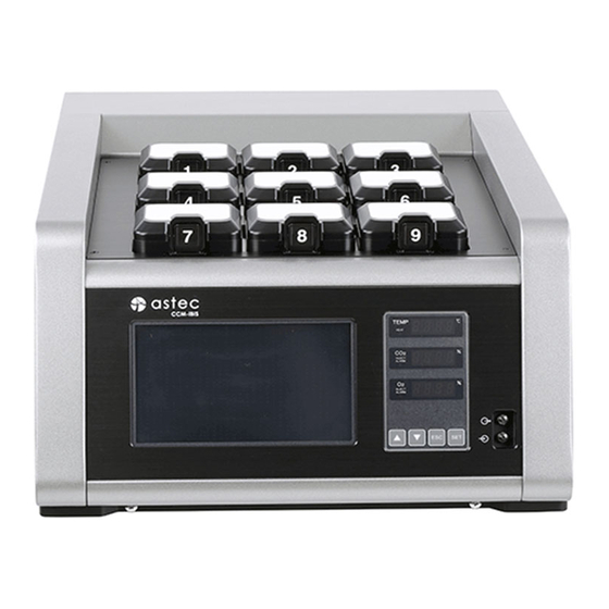
Innovative Blastocyst Incubator System
CCM-iBIS
Instruction Manual
Caution
Before using this product, be sure to read this instruction
manual carefully in order to use it properly.
After reading the manual, keep in an appropriate place which is
easily accessible to operators.
Please note that loss of substances caused by malfunction of
the product will not be compensated by ASTEC.
Advertisement
Table of Contents

Subscribe to Our Youtube Channel
Related Manuals for ASTEC CCM-iBIS

Summary of Contents for ASTEC CCM-iBIS
- Page 1 After reading the manual, keep in an appropriate place which is easily accessible to operators. Please note that loss of substances caused by malfunction of the product will not be compensated by ASTEC.
-
Page 2: Table Of Contents
Contents Points to Note............................1 Safety Precautions ..........................2 Warranty Information.......................... 8 Points to be Strictly Adhered to......................8 Caution Labels Attached to the Product................... 10 Characteristics/Overview of the Product ..................11 Names and Conformation of Individual Parts of the Main body, Accessories, and Consumables .. 11 Checking the Installation Location .................... - Page 3 Contents 1-28 Flowchart of Software Installation ................. 32 1-29 Flowchart of Software Version Information Display ............32 1-30 Displaying the Temperature of Each Incubation Chamber ........... 33 Alarms .............................. 34 PC Operation Procedures ..................... 35 Start Screen ........................35 Login Screen ......................... 35 How to Terminate ......................
-
Page 4: Points To Note
Keep the instruction manual in an appropriate place so that the manual is easily accessible when needed. If any pages are missing or out of order in the instruction manual, contact ASTEC or your dealer, for replacement. The instruction manual has been written carefully. Nevertheless, if any erroneous or missing description is found, contact ASTEC or your dealer. -
Page 5: Safety Precautions
Safety Precautions The descriptions below concern safety and are very important. Read the descriptions carefully and be sure to follow them. The instructions presented in this section aim to prevent occurrence of any harm or damage to the user and other persons by ensuring the user handles the product in a proper and safe manner. Precautions for possible misuse of the product are categorized in three levels "danger", "warning", and "caution", so that the degree of harm and damage and that of imminence are clearly recognized. - Page 6 Safety Precautions Warning The product must be installed by your dealer or a certified company. If installed by the customer, any inappropriate work may result in gas leakage, electric shock, or fire. The product must be installed horizontally on a floor with sufficient strength for the weight of the product.
- Page 7 Safety Precautions Warning After removing any dust, firmly and completely insert the power cable plug into the outlet. If dust stays on the power cable plug or the plug is inserted incompletely, heat generation and fire may result. When removing the power cable plug, be sure to hold on the plug body (not the cable). The power cable may be damaged, resulting in an electric shock or fire due to short circuit.
- Page 8 Turn off the power switch, and be sure to remove the power cable from the outlet. Then, contact your dealer or ASTEC. Caution The service life of this product is seven years after purchase.
- Page 9 Safety Precautions Caution Do not scratch or damage the power cable or the power cable plug. Stepping on, modifying, pulling, twisting, or bundling the power cable may damage the cable, resulting in fire or electric shock. Route the power cable so that it is not caught accidentally and is not disconnected. Do not place any object near the outlet, so that the power cable can be immediately disconnected when needed.
- Page 10 In the case where the vibration of the motor becomes extraordinary or an unusual sound is generated when the product is in operation, immediately stop using the product, and contact your dealer or ASTEC. When fertilized eggs are being observed on the Live screen, illumination for observation is kept On.
-
Page 11: Warranty Information
Warranty Information The period of the product warranty by ASTEC is two years after delivery. If a defect attributed to ASTEC occurs during the warranty period, the product will be repaired or components will be replaced without any charge. Note that the warranty will not be applied in the cases below and will not apply to any damage attributed to factors other than those described in this instruction manual: ... - Page 12 On the PC used with this system, do not install applications other than ones installed by ASTEC. Intended proper operations and performance may not be presented. For this product, only µDrop GPS culture dishes are usable.
-
Page 13: Caution Labels Attached To The Product
Caution Labels Attached to the Product The caution labels have been attached to the positions on the rear of the main body, shown below. The individual cautions are as follows: Dangerous position: Power cable plug Description: If not connected, short circuit can result in electric shock. -
Page 14: Characteristics/Overview Of The Product
Characteristics/Overview of the Product This product is cultivation equipment presented through integration of a multi-gas incubator for cultivation of fertilized eggs and a microscopic system for microscopic observation. For observation, fertilized eggs do not need to be taken out of the cultivation equipment. This allows a reduction in the stress of fertilized eggs caused by changes of temperature and gas concentration, risks of overlooking fertilization and other incidents on the images, and other risks attributed to relocation at the time of observation of fertilized eggs. - Page 15 Names and Conformation of Individual Parts of the Main body, Accessories, and Consumables Incubation chamber lid Unlock tab LED indication panel Touch panel monitor Level adjuster USB port Sampling port Level adjuster Exhaust fan Power switch Circuit protector Power inlet gas supply port gas supply port External output port...
-
Page 16: Checking The Installation Location
Checking the Installation Location Install the product on a level gantry located on a sturdy, level floor. For the installation, choose a sturdy, level floor with no bumps. If the product is installed in a bumpy place or not horizontally, the installation of the product becomes unstable and malfunction or personal injury can result. -
Page 17: Points To Note For Installation
Points to Note for Installation Removing packing materials Remove all product packing materials including plastic bags, drying agents, and tape. Adjusting with the adjusters At the installation location of the product, turn the adjusters so that the product is installed horizontally. -
Page 18: Points To Note For Cleaning
Points to Note for Cleaning This product was manufactured and stored with extreme care. Nevertheless, the incubation chambers are expected to be cleaned before the using the product, and the chambers are expected to be periodically cleaned after the start of use. Before starting cleaning work, wipe off dirt and dust in the installation area, so that work will be performed in a clean environment. -
Page 19: Setting Dishes
Setting Dishes For this product, only µDrop GPS Dish are usable. Set culture dish to dish holder. Position the culture dish so that the alignment projection on the bottom of the dish fits into the notch of the dish holder, shown in figure 1. If this alignment is inappropriate, capture misalignment can occur at the time of image capture. -
Page 20: How To Use - Setting The Incubator
How to Use - Setting the Incubator Setting the Incubator Figure Incubator controller Heat indicator O concentration indication Temperature indication DOWN key CO UP key injection/alarm indicator CO ESC/SILENCE key concentration indication ... -
Page 21: Temperature Setting
How to Use - Setting the Incubator Temperature Setting Temperature setting can be made for "ch 1" to "ch 9". Press and hold [SET] for 1 second or longer to make the temperature indication flash. When it is flashing, press SET, so that channel number is shown on the temperature indication section. -
Page 22: Temperature Lower-Limit Setting (Temperature Fall Alarm)
How to Use - Setting the Incubator Temperature Lower-limit Setting (Under Temperature Alarm) In the same manner as temperature setting, temperature lower-limit setting can be made for each control channel. Press and hold [SET] for 1 second or longer to make the temperature indication flash. When it is flashing, press SET, so that channel number is shown on the temperature... -
Page 23: O2 Setting
How to Use - Setting the Incubator Setting This item allows to preset the concentration of O gas to be used. Press and hold [SET] for 1 second or longer to make the temperature indication flash. Then, press SILENCE twice to make O concentration indication flash. -
Page 24: How To Use - Fine Adjustment Of The Incubator
How to Use - Fine Adjustment of the Incubator [Fine-adjustment mode] The fine-adjustment mode allows fine adjustment of the temperature sensor, setting of PID control parameters, and fine adjustment of the CO and O sensors. Press and hold ESC/SILENCE for 1 second or longer to move to the fine-adjustment mode. If no operations are performed for about 10 seconds in the setting mode, the normal display mode is restored. -
Page 25: Temperature Control P (Proportion) Setting
How to Use - Fine Adjustment of the Incubator Temperature Control P (Proportion) Setting * Normally, do not change this setting. Press and hold ESC/SILENCE for 1 second or longer to display temperature fine-adjustment mode indication When in this display, press SET, so that channel number is shown on the temperature indication section. -
Page 26: Temperature Control Arw (Anti-Reset Wind-Up) Setting
How to Use - Fine Adjustment of the Incubator 1-12 Temperature Control ARW (anti-reset wind-up) Setting * Normally, do not change this setting. Press and hold SILENCE for 1 second or longer to display temperature fine-adjustment mode indication When in this display, press SET, so that channel number is shown on the temperature indication section. -
Page 27: Co 2 Offset Setting
How to Use - Fine Adjustment of the Incubator 1-14 CO Offset Setting offset setting allows to adjust so that the output value of the CO sensor will be 0% in the atmospheric environment. Enter the difference from CO indication values so that 0.0% will be indicated when detection is performed by the CO sensor in the atmospheric environment. -
Page 28: O 2 Offset Setting
How to Use - Fine Adjustment of the Incubator When in this display, press UP once or DOWN five times to display CO fine-adjustment mode indication Then, press SET to switch the indication to CO SPAN setting indication Moreover, when in this display, press UP three times or DOWN once to display CO alarm delay time setting indication... -
Page 29: O 2 Alarm Setting
How to Use - Fine Adjustment of the Incubator 1-18 O Alarm Setting alarm setting allows to set a tolerance for alarm generation, relative to the O concentration preset through O setting. If 1.0 is set for example, the tolerance will be ±1.0%. Press and hold SILENCE for 1 second or longer to display temperature fine-adjustment mode indication... -
Page 30: Version Indication
How to Use - Fine Adjustment of the Incubator 1-20 Version Indication This allows display of the firmware version. Press and hold SILENCE for 1 second or longer to display temperature fine-adjustment mode indication When in this display, press UP five times or DOWN once to display version indication on the temperature indication section and display the current version number on the CO indication section. -
Page 31: Flowchart Of The Fine-Adjustment Mode
How to Use - Fine Adjustment of the Incubator 1-22 Flowchart of the Fine-adjustment Mode Normal display 1 second Temperature setting To 1-23 Flowchart of Temperature Setting concentration setting To 1-24 Flowchart of CO Concentration Setting concentration setting To 1-25 Flowchart of O Concentration Setting Flow rate setting To 1-26 Flowchart of Flow Rate Setting... -
Page 32: Flowchart Of Temperature Setting
How to Use - Fine Adjustment of the Incubator 1-23 Flowchart of Temperature Setting Temperature setting Channel selection ON/OFF setting ON/OFF Change with Increase by 0.01 Channel selection Offset setting (Unit: ºC) Change with Increase by 0.01 Rounding-out value (Unit: ºC) setting Change with Channel selection... -
Page 33: Flowchart Of Co 2 Concentration Setting
How to Use - Fine Adjustment of the Incubator 1-24 Flowchart of CO concentration setting concentration Increase by 0.1 span setting setting (Unit: %) Change with Increase by 0.1 offset setting (Unit: %) Change with Use of CO alarm ON/OFF Change with Increase by 1 alarm time... -
Page 34: Flowchart Of O 2 Concentration Setting
How to Use - Fine Adjustment of the Incubator 1-25 Flowchart of O concentration setting concentration Increase by 0.1 span setting setting (Unit: %) Change with Increase by 0.1 offset setting (Unit: %) Change with Use of O alarm ON/OFF Change with Increase by 1 alarm time... -
Page 35: Flowchart Of Flow Rate Setting
How to Use - Fine Adjustment of the Incubator 1-26 Flowchart of Flow Rate Setting Flow rate sensor 1 Increase by 1 Flow rate setting Flow rate threshold setting (Unit: ml/minute) Change with Increase by 1 Flow rate offset (Unit: ml/minute) Change with Increase by 1 Flow rate monitor time... -
Page 36: Displaying The Temperature Of Each Incubation Chamber
How to Use - Incubator Temperature Indication 1-30 Displaying the Temperature of Each Incubation Chamber When in the normal mode, this equipment indicates the temperature of only incubation chamber To check the temperature of another incubation chamber, press and hold SILENCE and SET at the same time for about 2 seconds. -
Page 37: Alarms
Alarms Over Temp Alarm When the temperature of any incubation chamber exceeds the specified Over Temp Alarm setting for any reason, Over Temp Alarm is indicated and alarm beeps are generated. For Over Temp Alarm indication, the corresponding incubation chamber number and the current temperature following "o"... -
Page 38: Pc Operation Procedures
On, the confirmation window below is displayed on the screen of the PC. Press [Yes] to proceed to the next step. The screen which indicates start of CCM-iBIS is displayed as below. When the software is started, checkup of the saved files and the database is executed and progress is shown with a progress bar. -
Page 39: How To Terminate
PC Operations - Termination/ Main Screen/ Dish-In Processing How to Terminate Before turning Off the main body, be sure to shut down the PC. To shut down the PC, touch power button at the bottom right of the login screen. To shut down when in login status, log out first, and then shut down as described above. - Page 40 PC Operations - Dish-In The screen allows to identify (before starting cultivation) which wells contain fertilized eggs, to view live images for image capture point alignment, and to enter sample-related information. If the previous cultivation information still remains when executing Dish-In processing, enter new information after pressing the CLEAR buttons ...
-
Page 41: Preview
PC Operations - Preview Preview Use when observing fertilized eggs in dishes. This function allows to observe wells registered in the Dish-In procedure. On the Main screen, double-tapping the target dish displays the Preview screen. Double-tap Double-tap Well map: Shows the locations of wells in a dish. Double-tapping the position of the target well makes the observation camera shift to that position, followed by display of the Live screen. -
Page 42: Live Display
PC Operations - Live Display Live Display Double-tapping a well on the Preview screen displays the Live screen. Touching a tab on the screen highlights the tab to indicate that it has been selected. As for the cursor buttons, the arrow buttons become non-functional and are grayed out when they do not need to be used, depending on selected items. - Page 43 PC Operations - Live Display Executing image capture on the Live screen displays the captured image. As for the cursor buttons, the arrow buttons become non-functional and are grayed out when they do not need to be used, depending on selected items. Captured-image display: An image captured on the Live screen is shown.
-
Page 44: Dish-Out
PC Operations - Dish-Out Dish-Out After cultivation is ended, perform Dish-Out processing to complete the end procedure. To execute Dish-Out processing, touch the dish to be finished , so that it is highlighted and its button . The background of the dish turns black. frame turns yellow. -
Page 45: Dish Info
PC Operations - Dish Info (Dish Information) Dish Info Use to correct information entered in the Dish-In procedure. Touching the Dish Info button on the Main window switches the screen. The displayed screen allows to change preset items and add items (sample name, ID number, birth date, etc.). -
Page 46: Capture
PC Operations - Capture 2-10 Capture This allows image capture of a specified dish. Check the checkbox of the dish to be captured and start the procedure. button displays the dialog "Select capture dishes" . Pressing . Image capture is Check the checkbox of the dish to be captured, and then press started. -
Page 47: Image Check
PC Operations - Image Check 2-11 Image Check This function allows checking of saved image files. Images captured for each well in the image display of a dish are shown. Moving the slider allows display of images in the temporal sequence of capture. Images captured most lately are shown at the top, and the oldest images are shown at the bottom. - Page 48 PC Operations - Image Check Slide show Enlarged display Display area of captured images X-Y shift tab: An image enlarged (ZOOM IN) can be scrolled vertically and horizontally with the cursor buttons. Z axis shift tab: When shown images include z slices, the cursor buttons can be used to change the z direction (pint axis).
-
Page 49: File
PC Operations - File Transfer 2-12 File 2-12-1 Export Files (Image file transfer) Use when transferring captured images to an external location. File transfer is to be performed for each sample. Touching the Export Files radio button makes switches the display to the Export Files screen. Enter a transfer destination directory into field , or touch button and then use the browse... -
Page 50: Deleting Image Files
PC Operations - File Deletion 2-12-2 Deleting image files Use when deleting captured images. File batch-deletion is to be performed for each sample. Touching the Delete Files radio button switches the display to the Delete Files screen. From the pull-down menu of Patient Name or Patient ID, select the name or ID of the target sample. -
Page 51: Report Output
PC Operations - Report Output 2-12-3 Report Output 2-12-3-1 Preparation For preparation of report generation, an image to be put on the report has to be selected. On the Image Check screen shown in 2-11 Image Check, select an image to be put on the report. When the selected image ... - Page 52 PC Operations - Report Output To create a new folder, touch button , use the directory selection dialog to specify a directory, enter a new folder name into field , and then touch New Folder . From the pull-down menu of Patient Name or Patient ID, select the name or ID of the target sample.
-
Page 53: User Management
PC Operations - User Management 2-13 User Management In this section, set user privileges regarding login. Levels A to E can be set to users. The screen here allows to set what can be operated with the individual levels. User management based on levels in this manner makes it easy to change what can be operated by users. -
Page 54: Changing User Levels And Remarks
PC Operations - User Management Create User dialog is displayed. Enter a user name, user level, password, and (as needed) remark, and then press button to complete the registration. button is pressed, the dialog is closed without registration being executed. 2-13-2-2 Changing user levels and remarks. -
Page 55: Log Information
PC Operations - Log Information 2-13-3 Log information Touching the Log tab displays the log information screen. The screen allows display of the following log information. a. File log (File Log) b. Operation log for each user (Operation Management Log) c. -
Page 56: Operation Log For Each User
PC Operations - Log Information When specifying a file save location in , the dialog shown to the right is displayed. Select the desired folder. 2-13-3-2 Operation log for each user With a user name selected, record of operation details by the user is shown for each month. Select the target user from the pull-down menu . -
Page 57: User Addition/Deletion Log
PC Operations - Log Information 2-13-3-3 User addition/deletion log This log shows when user addition and deletion were performed by which users. Select the desired year/month from the pull-down menu to display the target file log. Specify a save location to save as a text file. ... -
Page 58: System Settings
PC Operations - System Settings/ Folder Settings 2-14 System Settings Make system-related settings including file save location and schedule settings. 2-14-1 Folder settings (Folder) Specify a folder for saving captured images and output sample-related information. Specify IP Address: Enter the IP number of save location NAS. ... -
Page 59: Schedule Pattern Settings (Monitoring Patterns)
PC Operations - Schedule Pattern Settings 2-14-2 Schedule Pattern Settings (Monitoring Patterns) Set schedule for auto image capture. The settings made here can be selected in the "Dish-In" procedure. Pattern: As a schedule pattern, nine customizable patterns can be selected besides fixed PN Check. -
Page 60: Z-Slice Setting (Focal Planes)
PC Operations - Z-slice Setting 2-14-4 Z-slice Setting (Focal Planes) Make settings for z-axis slices for image capture. Distance between Focal Planes: Set an inter-slice distance. Select from the pull-down menu. Focal Plane Range: Set the width of the entire portion to be sliced. Select from the pull-down menu. -
Page 61: Specifications
Specifications Model CCM-iBIS External dimensions 530 mm (W) x 860 mm (D) x 381 mm (H) *Projections included Number of settable dishes 9 (60-mm µDROP GPS Dish) Inside-chamber dimensions 72 mm (W) x 84 mm (D) x 18 mm (H) Capacity: Approx. 108 ml... -
Page 62: External Output
External Output This equipment is able to output contact-originated signals when an alarm sounds or the power is turned off. It is also able to output analog signals (represented by voltage) that indicate the temperature of each incubation chamber and CO concentration. -
Page 63: External Dimensions
External Dimensions... - Page 64 For any inquiries about this product, please contact your dealer or ASTEC. ASTEC CO., LTD. Website : www.astec-bio.com/global E-mail : info@astec-bio.com Headquarters 4-6-15 Minamizato, Shime, Kasuya, Fukuoka 811-2207, Japan TEL +81-92-935-5585 FAX +81-92-936-6613 Fukuoka Sales Office 5F, Astec Bldg., 4-6-15 Minamizato, Shime, Kasuya, Fukuoka...
Need help?
Do you have a question about the CCM-iBIS and is the answer not in the manual?
Questions and answers
Dear Sir/ Madam, My question is, CCM-iBIS has 9 chambers for different patients. Can the development of the embryos be monitored online? Is it possible for this online monitoring to be by different specialists, each responsible for different patients. These specialists do not have access to the embryos of the other specialist