USA Notification Warning: Changes or modifications to this unit not expressly approved by the party responsible for compliance could void the user’s authority to operate the equipment. Note: This equipment has been tested and found to comply with the limits for a Class A digital device, pursuant to Part 15 of the FCC Rules.
Page 4
Power On This symbol indicates the principal on/off switch is in the on position. Power Off This symbol indicates the principal on/off switch is in the off position.
Figure 2.3: AutoView 2015 Switch Configuration with a Cascaded Switch ... 12 Figure 2.4: AutoView 2015 Switch Configuration with Legacy KVM Switches ... 13 Figure 2.5: AutoView Switch Configuration with AutoView 1415/1515/2015 Switches... 14 Figure 3.1: Example of Configured Main Dialog Box ... 17 Figure 3.2: Setup Dialog Box (User)...
Page 10
AutoView 1415/1515/2015 Switch Installer/User Guide Figure 4.2: User Setup Menu (Administrator Only)... 44 Figure 4.3: User Edit Menu (Administrator Only)... 45 Figure 4.4: User Access Menu (Administrator Only)... 45 Figure A.1: AVRIQ Status Dialog Box ... 48 Figure A.2: AVRIQ Upgrade Dialog Box... 49...
Page 11
LIST OF T A BL ES List of Tables Table 2.1: Legacy Switch Support ... 12 Table 3.1: OSCAR Interface Status Symbols ... 18 Table 3.2: OSCAR Interface Navigation Basics ... 19 Table 3.3: Setup Features to Manage Routine Tasks for Your Servers... 21 Table 3.4: OSCAR Interface Status Flags ...
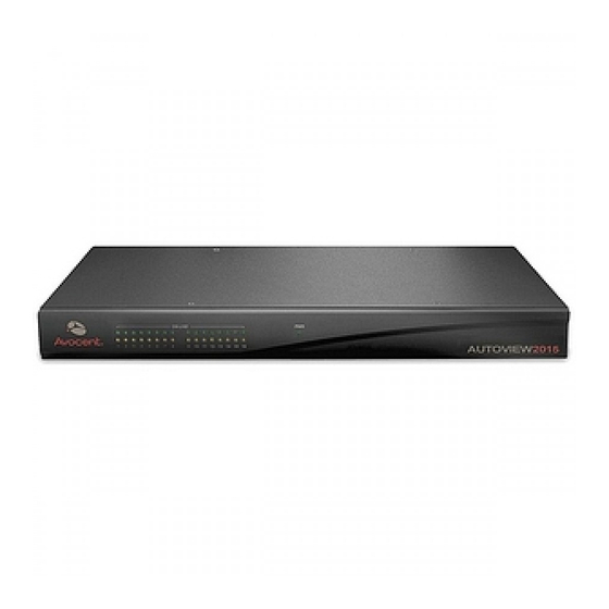
The AutoView 1415/1515/2015 switches also feature user peripheral ports for PS/2 and USB keyboards and mice. NOTE: With the exception of USB capability, all references to AutoView 1415/1515/2015 switches are applicable to AutoView 1400/1500/2000 switches respectively.
Page 14
Both the AutoView switch and the AVRIQ modules are Flash upgradable. See Appendix A for more information. NOTE: Firmware available for the AutoView 1415/1515/2015 switch is also compatible with the AutoView 1400/ 1500/2000 switch, but it is not compatible the AutoView 2020/2030 switch.
Cascading expansion Each AutoView switch supports up to 16 directly attached servers and can conveniently scale to support more. You can expand your system using cascadable Avocent products such as other AutoView or OutLook switches. This extra “cascade” of units allows you to attach up to 256 ®...
To avoid potentially fatal shock hazard and possible damage to equipment, please observe the following precautions: • Do not use a 2-wire extension cord in any Avocent product configuration. • Test AC outlets at the computer and monitor for proper polarity and grounding.
Page 17
Use only with grounded outlets at both the computer and monitor. When using a backup Uninterruptible Power Supply (UPS), power the computer, the monitor and the AutoView switch off the supply. NOTE: The AC inlet is the main disconnect. Rack mount safety considerations •...
CHA PTER Installation Getting Started Before installing your AutoView switch, refer to the following list to ensure you have all items that shipped with the AutoView switch, as well as other items necessary for proper installation. Supplied with the AutoView switch •...
Remove the first two screws on each side of the switch. Line up the holes in the “long side” of the kit’s side brackets with the screw holes in the switch. With a Phillips screwdriver, fasten the mounting brackets to the switch using two screws on each side.
- Disconnect the power from the unit by unplugging the power cord from either the electrical outlet or the unit. Configuration Port (for updating firmware) Analog User A Figure 2.2: Basic AutoView Switch Configuration NOTE: Only the AutoView 1515 and the AutoView 2015 switches support two simultaneous users. Analog User B AutoView Switch...
You can cascade multiple AutoView 1415/1515/2015 switches to enable one or two users to connect to as many as 256 servers. In a cascaded system, each ARI (Avocent Rack Interface) port on the main AutoView switch will connect to the ACI (Avocent Console Interface) port on each cascaded AutoView switch.
Page 23
Connect the cascaded AutoView switch to each server as described in the previous Installing the AutoView Switch section. Connect the local peripherals to analog user A and/or B of the main switch as described in To connect local peripherals. Attach one end of the CAT 5 cabling that will run between your main and cascaded AutoView switch to the RJ-45 ACI port on the cascaded AutoView switch.
AutoView 1415/1515/2015 Switch Installer/User Guide Figure 2.3: AutoView 2015 Switch Configuration with a Cascaded Switch Adding Legacy Switches You can add legacy switches to the AutoView switching system for easy integration into your existing configuration. In a cascaded system, each ARI port will accommodate up to 24 servers.
Chapter 2: Installation Local Analog User A AutoView 2015 Switch AVRIQ Module PS/2, USB, Sun and serial cables are available AVRIQ Module OutLook ES Switch AutoView 200/400 Switch Server 1 Server 2 Figure 2.4: AutoView 2015 Switch Configuration with Legacy KVM Switches...
Local Analog User A AVRIQ Module PS/2, USB, Sun and serial modules are available Figure 2.5: AutoView Switch Configuration with AutoView 1415/1515/2015 Switches NOTE: The PS2IAC modules can be utilized in Figure 2.5. Local Analog User B AutoView 1415/1515/2015 Switch...
Mount the primary KVM switch into your rack cabinet. Connect one end of a CAT 5 cable to an available port on the back of your AutoView switch. Attach the keyboard, monitor and mouse connectors of the AVRIQ module to a user port on your cascaded switch.
Controlling Your System at the Analog Ports The AutoView switch features one or two analog port sets on the back of the switch that allow you to connect a monitor and a PS/2 or USB keyboard and mouse for direct analog access. The AutoView switch uses the OSCAR interface, featuring intuitive menus to configure your system and select servers.
AVRIQ modules and IACs are blocked by the indicated user channel (black channel letter) . Selecting servers Use the Main dialog box to select servers. When you select a server, the switch reconfigures the keyboard and mouse to the proper settings for that server.
Print Screen status flag on your desktop displays Free. Soft switching Soft switching is the ability to switch servers using a hotkey sequence. You can soft switch to a server by pressing Print Screen Screen Delay Time and you press the key sequences before that time has elapsed, the OSCAR interface will not display.
Page 32
Deletes characters in a text box. Pages up and down through Name and Port lists and Help pages. Type from the keyboard or keypad. Logs the current user out of the switch (only available when Enable Local User Accounts is checked on the Security screen).
You can configure your AutoView switch from the Setup menu within the OSCAR interface. Select the Names button when initially setting up your switch to identify servers by unique names. Select the other setup features to manage routine tasks for your servers from the OSCAR interface menu.
AutoView 1415/1515/2015 Switch Installer/User Guide Figure 3.2: Setup Dialog Box (User) Figure 3.3: Setup Dialog Box (Admin) NOTE: Figure 3.3 displays for the Administrator if Local User Accounts are enabled, or for all user if Local User Accounts are disabled.
Figure 3.4: Names Dialog Box NOTE: If the server list changes, the mouse cursor will turn into an hourglass as the list is automatically updated. No mouse or keyboard input will be accepted until the list update is complete. To assign names to servers: In the Names dialog box, select a server name or port number and click Modify.
The AutoView switch automatically discovers cascaded KVM switches, but you will need to specify the number of ports on the cascaded switch through the Devices dialog box. You will see an Sw-8 or Sw-24 display in the Type category for the cascaded switch. Select the switch from the list and the Modify button displays, allowing you to assign it the appropriate number of ports.
Figure 3.7: Device Modify Dialog Box Choose the number of ports supported by your cascaded switch and click OK. If the number of desired ports is not listed, click Other and type in port number between 4 and 24 ports.
To perform a soft switch, see Soft switching in this chapter. Setting the keyboard country code The AutoView 1415/1515/2015 switch can be configured to recognize a variety of keyboards. The default setting is for a US keyboard. If you wish to change this configuration, the Keyboard dialog box allows you to select a different keyboard country code.
Figure 3.9: Keyboard Box To change the keyboard country code: Press Print Screen Click Setup-Keyboard. The Keyboard dialog box displays. Select your desired keyboard country code and click OK. A Keyboard Warning dialog box will appear to confirm your changes. Click OK for changes to take effect.
AutoView 1415/1515/2015 Switch Installer/User Guide Select your desired language. Click OK for changes to take effect. Figure 3.11: Language Dialog Box Controlling the status flag The status flag displays on your desktop and shows the name or EID number of the selected server or the status of the selected port.
Figure 3.12: Flag Dialog Box To determine how the status flag is displayed: Select Name or EID to determine what information will be displayed. Select Displayed to show the flag all the time or select Timed to display the flag for only five seconds after switching.
NOTE: If a password has been previously set, you will have to enter the password before you can access the Security dialog box. If you should lose or forget your password, please contact Avocent Technical Support about returning your switch for service. See Appendix D:Technical Support for contact information.
Page 43
Type the number of minutes for Inactivity Time (from 1 to 99) to delay activation of password protection and the screen saver feature. For Mode, select Energy if your monitor is E CAUTION: Monitor damage can result from the use of Energy mode with monitors not compliant with NERGY (Optional) Click Test to activate the screen saver test which lasts 10 seconds then returns you to the Security dialog box.
Page 44
AutoView 1415/1515/2015 Switch Installer/User Guide Choose Energy if your monitor is E CAUTION: Monitor damage can result from the use of Energy mode with monitors not compliant with NERGY (Optional) Click Test to activate the screen saver test which lasts 10 seconds then returns you to the Security dialog box.
Print Screen Displaying Version Information The OSCAR interface enables you to display the versions of the AutoView switch, as well as the AVRIQ module and IAC module firmware. For optimum performance, keep your firmware current. For more information, see Appendix A.
AutoView 1415/1515/2015 Switch Installer/User Guide Figure 3.16: Target Selection Dialog Box (Admin) Select an AVRIQ or IAC module to view and click the Version button. The Target Version dialog box displays. For more information on loading firmware, see Appendix A.
Figure 3.18: Firmware Warning Dialog Box To decommission an AVRIQ module: Decommissioning an AVRIQ module restores the factory defaults in Sun, USB and PS/2 AVRIQ modules only. Press Print Screen Click Commands Click the Target button to view individual AVRIQ module version information. The Target Selection dialog box displays.
AutoView 1415/1515/2015 Switch Installer/User Guide To add servers to the scan list: If the OSCAR interface is not open, press Click Setup - Scan. The Scan dialog box displays. Figure 3.19: Scan Dialog Box The dialog box contains a listing of all servers attached to your appliance. Click the checkbox next to the servers you wish to scan.
You can validate the integrity of your system through the Run Diagnostics command. This command checks the main board functional sub-systems (memory, communications, switch control and the video channels) for each system controller. When you select the Run Diagnostics option, you will receive a warning indicating that all users (remote and local) will be disconnected.
AutoView 1415/1515/2015 Switch Installer/User Guide NOTE: AVRIQ or IAC modules may appear to be offline while being upgraded. Figure 3.21: Diagnostics Dialog Box Next to each item to be tested, you will see a pass (green circle) or fail (red x) symbol display to the left of each item as that test finishes.
Figure 3.22: Diagnostics Warning Dialog Box Click OK to begin diagnostics. -or- Click X or press Escape All users are disconnected and the Diagnostics dialog box displays. As each test is finished, a pass (green circle) or fail (red x) symbol displays. The test is com- plete when the last test’s symbol displays.
AutoView 1415/1515/2015 Switch Installer/User Guide Figure 3.23: Broadcast Dialog Box NOTE: Broadcasting Keystrokes - The keyboard state must be identical for all servers receiving a broadcast to interpret keystrokes identically. Specifically, the Caps Lock and Num Lock modes must be the same on all keyboards.
From the Commands dialog box, clear the Broadcast Enable checkbox. Changing Your Switch Mode Your AutoView switch allows you to connect to attached servers using two methods: Preemptive and Cooperative. Select Preemptive (default setting) to allow any user to select any server at any time; a request from another user disconnects the current user without warning.
Select either Preemptive or Cooperative as your Switch Mode. Click OK to save changes. Click X or press Setting the Share Mode feature The Share Mode feature of the AutoView 1415/1515/2015 switches allows two users to gain access to a primary server. To enable Share Mode:...
Advanced Operations Using Administrator Privileges The AutoView 1415/1515/2015 switches allow up to four users and one administrator to log into a switch, with the administrator having the ability to restrict users from accessing the targets via the Security menu. The administrator can edit, access and/or delete user accounts.
The User Setup menu allows the administrator to edit, access and/or delete a user account. The menu is only accessible if the Enable User Account checkbox is enabled in the Security menu. The AutoView 1415/1515/2015 switches will have four standard user accounts, with the default names of User1, User2, User3 and User4.
Chapter 4: Advanced Operations Figure 4.3: User Edit Menu (Administrator Only) The Username field displays default names that can be edited by the administrator. Usernames must be between 1 to 15 characters. Administrators can also set user passwords in the User Edit menu.
Page 58
AutoView 1415/1515/2015 Switch Installer/User Guide The Clear All button allows the administrator to clear access to all ports for a given user instead of deleting the account. The Check All button allows the administrator to assign all available KVM ports to any user.
Upgrading the AutoView switch You can upgrade the firmware of your AutoView switch by using a special update utility provided by Avocent. This utility automatically configures the port communications settings to allow direct downloading from the connected server. Items needed for the upgrade •...
High. CAUTION: While upgrading, do not use your server for anything else or switch between windows. Close all other windows if necessary. If the upgrade was unsuccessful (such as during a power outage), repeat the procedure.
Appendix B: Technical Specifications Table B.1: Product Specifications AutoView Switch Product Specifications ARI ports Number 8 (AutoView 1415/1515 switch), 16 (AutoView 2015 switch) Types PS/2, Sun, USB and serial AVRIQ modules or PS/2 and USB IACs Connectors RJ-45 Sync Types...
Page 63
Table B.1: Product Specifications (Continued) AutoView Switch Product Specifications AC-input 100 to 240 VAC Autosensing voltage rating AC-input current 0.5 A rating 18 AWG three-wire cable, with a three-lead IEC-320 receptacle on the power supply AC-input cable end and a country or region dependent plug on the power resource end...
AutoView 1415/1515/2015 Switch Installer/User Guide Appendix C: Sun Advanced Key Emulation Certain keys on a standard Type 5 (US) Sun keyboard can be emulated by key press sequences on a PS/2 keyboard. To enable Sun Advanced Key Emulation mode and use these keys, press and hold...
AVRIQ-USB modules. These keys function normally if your Sun servers are attached to the AutoView 1415/1515/2015 switch using an AVRIQ-VSN or AVRIQ-WSN module. Table C.2 lists the keyboard mapping that will take place when an AVRIQ-USB module is used in this setting.
Appendix D: Technical Support Our Technical Support staff is ready to assist you with any installation or operating issues you encounter with your Avocent product. If an issue should develop, follow the steps below for the fastest possible service. To resolve an issue: Check the pertinent section of this manual to see if the issue can be resolved by following the procedures outlined.
Need help?
Do you have a question about the AutoView 1415 and is the answer not in the manual?
Questions and answers