
Related Manuals for DAE Polaris 1000


Summary of Contents for DAE Polaris 1000
- Page 1 Polaris 1000 User’s Manual 2017/11/06 Version : 1.3us DAE Instrument Corp. http://www.DAEinstrument.com/...
- Page 2 Polaris 1000 User’s Manual Page 2...
- Page 3 Polaris 1000 User’s Manual Polaris 1000 User’s Manual, 2017, Nov. Copyright © 2017 DAE Instrument Corp. All rights reserved. DAE Controls LLC. 2707 Golfview Dr. 103 Troy Michigan 48084, USA Tel:+1-248-635-3708 Fax:+1-248-822-8138 e-mail:info@DAEcontrols.com DAE Headquarters 5F, No. 157, Xinhu 1 Road, Neihu District, Taipei 11494, Taiwan, R.O.C.
-
Page 4: Safety Precautions
Polaris 1000 User’s Manual Safety Precautions Please read these safety instructions before using this equipment. For safety purposes, please observe the following when unwrapping and installing the package: When opening the package, check that the contents have not been damaged during transit. - Page 5 Polaris 1000 User’s Manual Cleaning Use a dry cloth or dry brush to wipe away the dust, or use in conjunction with a vacuum cleaner to suck the dust as it is being wiped away. Do not use any water or other liquid cleaning agents.
-
Page 6: Table Of Contents
Polaris 1000 User’s Manual CONTENT INTRODUCTION ....................7 ..................7 ENERAL ESCRIPTION ......................7 EATURES ....................7 ERTIFICATIONS ....................7 PECIFICATIONS ..................8 RODUCT NFORMATION INSTALLATION ....................9 ....................10 RONT ANEL ...................... 11 ERMINALS ..................13 OUNTING ROCEDURE ..................13... -
Page 7: Introduction
The Polaris 1000 meter is an electronic kilowatt-hour (kWh) meter that is designed for permanent connection to an electrical service. It is designed for single phase applications. Polaris 1000 meters can be used in 1 phase 2 wire and 1 or 2 phase 3 wire configurations. 1.2 Features Revenue-grade accuracy ... -
Page 8: Product Information
Polaris 1000 User’s Manual 1.5 Product Information Polaris 1000 meters model No. Item Description – Polaris 1000 Series – 1-phase, 2 wire, 120V Configurations 1- or 2-phase, 3 wire, 120/208~240V – 50~200A CT Rating depends on CT current range – 400A –... -
Page 9: Installation
Installation of this device must be performed by qualified personnel according to these instructions and in conjunction with all applicable electrical codes. DAE Instrument and its representatives assumes no responsibility for any damage or injury resulting from the improper installation of this equipment. -
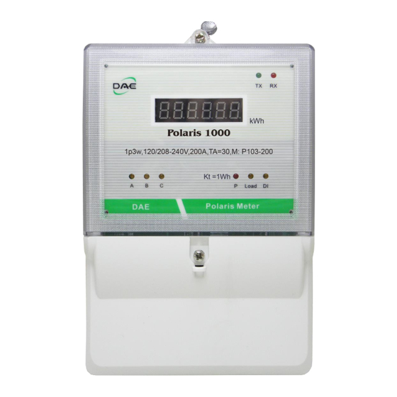
Page 10: Front Panel
Polaris 1000 User’s Manual 2.1 Front Panel 6-digit primary LCD display LED display for showing kWh and other parameters TX, RX Reserved A, B, C Phases A, B, C phase voltage inputs indicator Watthour test constant indicator Kt=1Wh (1000 imp/kWh) -
Page 11: Terminals
Polaris 1000 User’s Manual 2.2 Terminals Terminal cover removed Voltage input terminals (19) Phase A voltage input (20) Phase B voltage input (21) Phase C voltage input (22) Phase N voltage input CT input terminals (13) CT-A + Phase A CT + input... - Page 12 Polaris 1000 User’s Manual Terminal detail Voltage input terminals Use the proper size and wire type as per electrical regulations. Other terminals Make sure that the wires are screwed tightly onto the terminals and making good contact. Recommended wire size...
-
Page 13: Mounting Procedure
Verify that the dedicated CT being used is compatible with the type of Polaris. Note that the Polaris cannot be directly used with non-DAE dedicated CTs. Verify that the current rating of the dedicated CT being used is suitable for its intended load. -
Page 14: Conduit And Wire Ingress
Polaris 1000 User’s Manual 2.5 Conduit and Wire Ingress Regular terminal cover Each Polaris meter has two knockouts at the bottom. Both knockouts can be cut open for either 1/2" or 3/4" conduit. For voltage and CT wirings, cut open the knockout for 3/4" conduit. -
Page 15: Meter Installation
2.7 CT Installation The Polaris can only make use of the dedicated CTs provided by DAE. There are two types of dedicated CTs as shown in the following descriptions. - Page 16 Polaris 1000 User’s Manual Meter side Connect the CT white wire to the CT+ terminal on the meter, and the CT black wire to the CT– terminal on the meter. Please refer to section 2.2 on Terminals. Solid-core CT installation...
-
Page 17: Wiring Diagram
Polaris 1000 User’s Manual Wiring Diagram 1-phase, 2 wire Fuse = 120V Note : Please install a fuse for each voltage input. (Except the phase N) 1- or 2-phase, 3 wire Fuses , = 120V, V = 208~240V Note : Please install a fuse for each voltage input. (Except the phase N) -
Page 18: Measuring Multiple Loads With One Meter
Polaris 1000 User’s Manual 2.9 Measuring Multiple Loads with One Meter The loads must be the same configuration and come from the same power source. Each meter can accept 3 loads at most, each load needs to have its own set of CTs and each CT must be of the same rating. -
Page 19: Display
Polaris 1000 User’s Manual 3 Display The Polaris 1000 meter normally displays the kWh reading, but if a water meter feature is enabled, the display will toggle between the kWh (Page 5, ) and pulse count of the water meter (Page 9, 3.1 Startup Display... -
Page 20: Troubleshooting
Polaris 1000 User’s Manual 4 Troubleshooting The Polaris meters are fully calibrated and tested during production. The Polaris meters should work normally if installed properly by correctly following our installation guide. If the meter has any problem, please consider the following troubleshooting procedures. - Page 21 Polaris 1000 User’s Manual Problems or Symptoms Possible Causes and Solutions Any Voltage input indicators do not (a) Check to make sure that the voltage input light up. terminal wiring is connected properly. (b) Check the voltage input terminals are not damaged.
-
Page 22: Frequently Asked Questions
A. The Polaris meters are sold with the CTs included which cannot be used direct connects. The Polaris 1000 meters use DAE’s dedicated CTs and can accept neither regular 5A output CTs nor dedicated CTs from other suppliers. The CT input of the Polaris can only accept milli-amps which matches DAE’s dedicated... - Page 23 Polaris 1000 User’s Manual Q. What will happen if the polarities are reversed for each of the CT? A. The Polaris only considers the absolute value of the current and disregards the direction; thus, the current and energy values can only be positive. However, we still recommended that the CTs be connected with the correct wiring orientation.
-
Page 24: Warranty And Return Policy
The warranty is effective for a period of five years from the date of shipment. The buyer must inform DAE of the defect within 80 days after the defect is experienced or found. DAE’s responsibility is limited to repair, replacement, or refund, any of which may be selected by DAE in its sole discretion. -
Page 25: Supplementary Information
Polaris 1000 User’s Manual 7 Supplementary Information Please add fuses to the voltage input to protect damage from a short circuit. Our contact information US Website: www.DAEcontrols.com US Email: info@DAEcontrols.com US Phone: +1-248-635-3708 International Website: www.DAEinstrument.com International Email: info@DAEinstrument.com International Phone: +886-2-2793-6123 Note : This document may change without notice, please check our website for the latest version. - Page 26 Polaris 1000 User’s Manual Page 26...
- Page 27 Polaris 1000 User’s Manual Page 27...
Need help?
Do you have a question about the Polaris 1000 and is the answer not in the manual?
Questions and answers