Table of Contents
Advertisement
Quick Links
Spin Doctor
Tech Support 1 (800) 533-8324
SM
9 AM - 6 PM EST Monday - Friday
Performance, Inc.
One Performance Way
Chapel Hill, NC 27514
Made in China
www.peformancebike.com
PERFORMANCE and the Flying P Logo are registered marks of Performance, Inc.
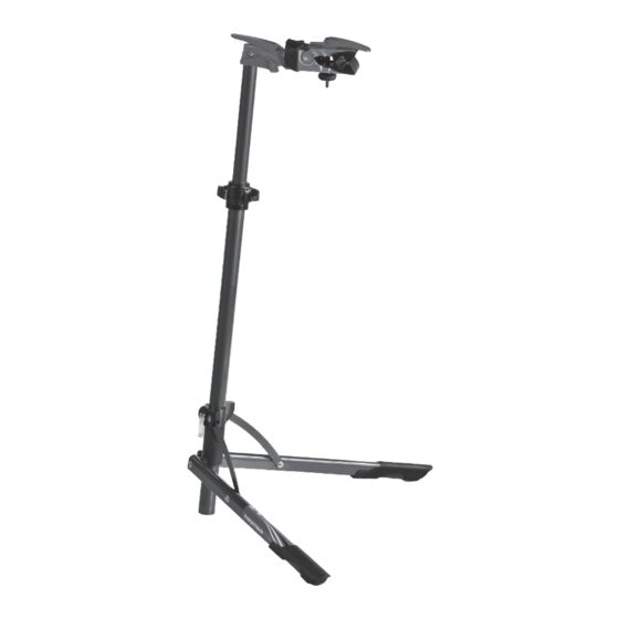
• Quick release clamp accommodates frame tubes up to 2" in diameter
• 360° indexed clamp rotation allows precise bicycle positioning
• Height adjustable from 36 ½" to 56 ½"
• Collapsible for easy storage and transport
• Wide base for stability
40-4134 0210_1
Spin Doctor
®
Team Workstand
Instructions For Use
Contents
• List of Parts
• Use
• Clamp Height
Adjustment
• Clamp Orientation
Adjustment
• Bicycle Clamping
• Bicycle Removal
• Folding the
Workstand
• Care and
Maintenance
• Important
• Warranty
Advertisement
Table of Contents

Related Manuals for Performance Spin Doctor


Summary of Contents for Performance Spin Doctor
- Page 1 • Height adjustable from 36 ½” to 56 ½” Performance, Inc. • Collapsible for easy storage and transport One Performance Way Chapel Hill, NC 27514 • Wide base for stability Made in China www.peformancebike.com 40-4134 0210_1 PERFORMANCE and the Flying P Logo are registered marks of Performance, Inc.
- Page 2 LIST OF PARTS 3. Undo the quick release (E) (fig.25). 4. Completely close the legs (A) , (B) by pushing 1 RH leg (Ref. A) the upper connection sleeve (D) upwards 1 LH leg (Ref. B) (fig.26). 1 lower connection sleeve(Ref. C) 5.
- Page 3 FOLDING THE WORKSTAND CLAMP MECHANISM HEIGHT ADJUSTMENT 1. Pull the safety slider (I) and, keeping it in 1.Unscrew the handle counterclockwise (G) (fig.7), holding the top tube (H) the release position (fig.20), flip the clamp firmly. After reaching the required height (fig.8), secure the top tube by turning mechanism (M) upwards (fig.21).
- Page 4 CLAMP MECHANISM ORIENTATION 3. Secure the bicycle (fig.15). 4. Close the clamp by pushing the lever (L) downwards (fig.16). ADJUSTMENT 5. Fine adjustment of clamping pressure is possible by turning the handwheel (R) 1. Release the clamp rotation fixing system by (fig.17) pulling the lever (L) upwards (fig.10).
Need help?
Do you have a question about the Spin Doctor and is the answer not in the manual?
Questions and answers