SimpliVity OmniCube CN-2000 Installation And Maintenance Manual
Cn-series
Hide thumbs
Also See for OmniCube CN-2000:
- Hardware installation and maintenance manual (51 pages) ,
- Hardware installation and maintenance manual (59 pages)

Related Manuals for SimpliVity OmniCube CN-2000


Summary of Contents for SimpliVity OmniCube CN-2000
- Page 1 OmniCube™ CN-Series Hardware Installation and Maintenance Guide CN-2000 CN-2200 CN-3000 CN-5000...
- Page 2 Corporation in the United States and certain other countries. All other trademarks are the property of their respective owners. Information in this document is subject to change without notification. Reproduction in any manner whatsoever without the written permission of SimpliVity Corporation is strictly forbidden. © SimpliVity Corporation 2015...
-
Page 3: Table Of Contents
Table Of Contents Preface 1 - Introduction to the CN-Series Hardware CN-Series Hardware Components Front Panel Description Back Panel Description Environmental and Technical Specifications Enclosure Size and Weights Power and Thermal Temperature and Humidity Vibration and Shock Limits Altitude and Airborne Contaminants Agency Compliance About Hardware Upgrades 2 - CN-Series Hardware Installation... - Page 4 CN-Series Hardware Installation and Maintenance Guide Viewing events or alarms in the vSphere Client Drive Monitoring Viewing Drive Status in the vSphere Client Power Supply Monitoring Viewing Power Supply Status in the vSphere Client Accelerator Card Monitoring Viewing Accelerator Card Status in the vSphere Client Accelerator Card is Not Detected Reverting an Accelerator Card to its Backup Firmware Network Interface Monitoring...
-
Page 5: Preface
Overview of the CN-Series system The foundation of the SimpliVity architecture is two or more high-performance and highly-available CN-Series systems. After installing the hardware in a rack and connecting power and network cables, you can create a datacenter within vCenter™... - Page 6 CN-Series Hardware Installation and Maintenance Guide Preface Support services from SimpliVity are available to answer your questions about the CN-Series system. Sim- pliVity provides online and telephone-based support services. Availability varies by country and product, and some services might not be available in your area. You can configure Phone Home support to automatically notify support about significant events.
-
Page 7: Introduction To The Cn-Series Hardware
1 - Introduction to the CN-Series Hardware This section contains information about the CN-Series system hardware components and describes the system specifications. CN-Series Hardware Components The minimum Federation configuration consists of a pair of high-performance and highly-available CN-Series systems. After you install the hardware, you can create a Federation within vCenter Server and configure each CN-Series system as a Federation OmniCube. -
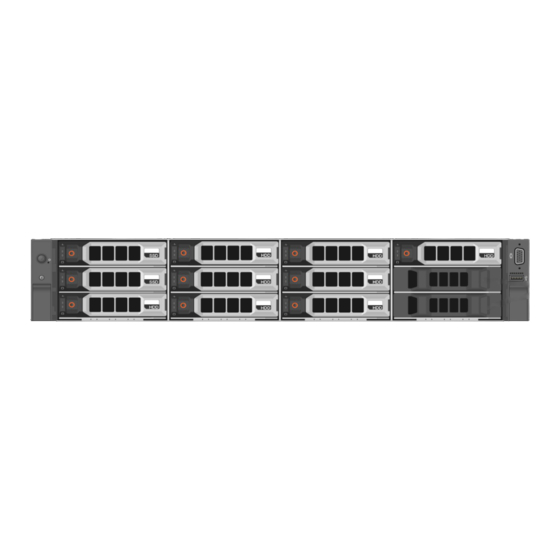
Page 8: Front Panel Description
Remote System IPMI processor and network port for remote, Web-based management. Management Contact your SimpliVity sales representative to learn about the vendor-specific interface cards currently supported for your platform. Front Panel Description The following image shows the front panel of a CN-2000 or CN-3000 with the bezel removed. - Page 9 CN-Series Hardware Installation and Maintenance Guide CN-Series Hardware Components Callout Component Description Power button Controls power to the CN-Series system and indicates whether there is power present. If the indicator is green, the CN-Series system is receiving power. Diagnostic Shows CN-Series system hardware error conditions. indicators System Enables you to find a CN-Series system within a rack.
-
Page 10: Back Panel Description
CN-Series Hardware Installation and Maintenance Guide CN-Series Hardware Components Callout Component Description Power button Controls power to the CN-Series system and indicates whether there is power to the CN-Series system. If the indicator is green, the CN-Series system is receiving power. Diagnostic Show CN-Series system hardware error conditions. -
Page 11: Environmental And Technical Specifications
(bottom) round LEDs. These interfaces are dedicated to SimpliVity Storage and Federation networks. Two 1GbE network interfaces, numbered 3 and 4, from left to right. Each 1GbE interface has link (left) and activity (right) square LEDs. These interfaces are dedicated to SimpliVity Storage and Federation networks. -
Page 12: Power And Thermal
CN-Series Hardware Installation and Maintenance Guide Environmental and Technical Specifications • CN-5000 Specification Inches 2U form factor 88.9 3.50 Maximum width (rack flange) 482.4 19.00 Enclosure width 444.0 17.50 Maximum height 87.3 3.43 Maximum depth (from rack flange) 28.50 723.0 28.5 The following table describes the weight of all CN-Series system models with all storage drives installed. -
Page 13: Altitude And Airborne Contaminants
If you would like to upgrade the system hardware components, contact SimpliVity Customer Service. Never install additional options in the other than those approved for installation by Warning: SimpliVity. Doing so will void your warranty and might cause serious system instability and potential data loss. -
Page 15: Cn-Series Hardware Installation
Federation. General Guidelines for Installing Hardware in a Rack SimpliVity recommends that you install the hardware in a rack according to the following guidelines: • Follow all safety guidelines stated in the rack's documentation, particularly when installing components into the locations at the top of the rack. -
Page 16: Task 1-Performing The Pre-Installation Tasks
CN-Series Hardware Installation and Maintenance Guide Task 1—Performing the Pre-Installation Tasks After completing the installation: • Organizing the power and network cables at the back of each CN-Series system. • Attaching the bezel to the front of each system. • Configuring VMware ESXi settings. •... -
Page 17: Unpacking The Shipping Carton
Unpacking the Shipping Carton When unpacking the shipping carton, be aware of the following: • The systems are heavy. Two or three people are required to lift and unpack the cartons and SimpliVity recommends the use of a datacenter equipment lift. -
Page 18: Shipping Carton Contents
Cable management arm Contains the cable management arm (CMA) assembly and installation documentation. USB flash drive Contains the SimpliVity vSphere™ Extension and SimpliVity Arbiter software and recovery software for resetting the system. PDF copies of the following documents are provided: •... -
Page 19: Rail Kit Components
CN-Series Hardware Installation and Maintenance Guide Task 1—Performing the Pre-Installation Tasks Obtaining Hardware That is Not Supplied on page 20 Rail Kit Components The rail kit contains these items: • Two sliding rail tool-less (fasteners optional) assemblies, left and right. •... -
Page 20: Obtaining Hardware That Is Not Supplied
CN-Series Hardware Installation and Maintenance Guide Task 1—Performing the Pre-Installation Tasks Obtaining Hardware That is Not Supplied You must provide additional hardware that is specific to your environment and not included in the shipping carton. Some of the necessary hardware depends on your network configuration. The following table lists the additional items might be required for installing the hardware: Hardware Description... -
Page 21: Switch Recommendations
CN-Series Hardware Installation and Maintenance Guide Task 1—Performing the Pre-Installation Tasks • Sliding rail system. The sliding rails allow you to fully extend the CN-Series system enclosure out of the rack for service. • Cable Management Arm (CMA). Use the CMA to organize and secure cables connected to the CN-Series system. -
Page 22: Understanding The Networks Used In A Federation
• You use the IPMI port for the initial setup and remote management. • SimpliVity supports three physical network configurations for a minimal two-OmniCube Federation. When you understand the network guidelines, you can install each CN-Series system in a rack. -
Page 23: Task 2-Installing Each Cn-Series System In A Rack
CN-Series Hardware Installation and Maintenance Guide Task 2—Installing Each CN-Series System in a Rack Task 2—Installing Each CN-Series System in a Rack You install the rails, which are included in the CN-Series system shipping carton, at the lowest available U space in the rack enclosure. - Page 24 CN-Series Hardware Installation and Maintenance Guide Task 2—Installing Each CN-Series System in a Rack • You have installed the rail kit. • You have read all supplied rack and CN-Series system safety information. This is important if you are installing the enclosure into the upper U locations of tall racks, where you need to use steps or platforms. To mount the enclosure into the rails: Extend each rail from the rack until it locks in place at lock A.
-
Page 25: Task 3-Connecting The Power Cables
Connect both CN-Series system power supplies to power sources. For high availability, you can connect each power supply to a different circuit. In addition, SimpliVity recommends that you use redundant uninterruptible power supply (UPS) systems to protect against a complete power outage. -
Page 26: Task 4-Connecting The Network Cables
CN-Series Hardware Installation and Maintenance Guide Task 4—Connecting the Network Cables Related Topics Shipping Carton Contents on page 18 Task 4—Connecting the Network Cables Each CN-Series system includes four network interfaces that are required for OmniCube Federation networks. These interfaces are labeled 1 to 4, from left to right. Network interfaces 1 and 2 are 10GbE, (SFP) and network interfaces 3 and 4 are 1GbE, as shown in the following image. -
Page 27: Organizing Cables
DNS RAC name to specify a rack location, your own asset number, or any other identifiable reference, but the name must be unique. • If you use DHCP to assign an IP address instead of using a static IP, SimpliVity recommends that you check the option and use the DNS RAC to reference the OmniCube. - Page 28 CN-Series Hardware Installation and Maintenance Guide Task 5—Configuring IPMI for Remote Management • An IP address. The address can be static or assigned by DHCP. • Provide the following using a static address: ◦ Gateway ◦ Subnet mask ◦ [Optional] Up to two DNS servers. The servers can be static or assigned by DHCP. •...
- Page 29 CN-Series Hardware Installation and Maintenance Guide Task 5—Configuring IPMI for Remote Management Check the box for Enable IPv4 Do one of the following: – Check the box for Enable DHCP – Assign a static IP address, Gateway, Subnet Mask and [Optional] DNS servers, if used. Verify the VLAN settings at the bottom of the screen complies with your network settings.
-
Page 30: Connecting To Ipmi And Launching The Virtual Console
CN-Series Hardware Installation and Maintenance Guide Task 6—Powering on the System Connecting to IPMI and Launching the Virtual Console You connect to IPMI to launch the Virtual Console, which you use to manage the target OmniCube remotely. You can also configure system settings, such as configuring the VMware ESXi instance installed on the OmniCube. -
Page 31: Attaching And Removing The Bezel
CN-Series Hardware Installation and Maintenance Guide Attaching and Removing the Bezel Attaching and Removing the Bezel Attach the bezel to ensure proper airflow and prevent accidental removal of drives. The bezel provides physical security for the drives in the front panel. To attach the bezel: Identify the front panel mounting lugs on the right side of the system. - Page 32 CN-Series Hardware Installation and Maintenance Guide Attaching and Removing the Bezel Rotate the left side of the bezel outward from the front panel and pull to the left, to simultaneously disengage the tabs on the right side of the bezel.
-
Page 33: Vmware Esxi Configuration
3 - VMware ESXi Configuration After you have configured IPMI (Intelligent Platform Management Interface) to launch the Virtual Console, you then use the Virtual Console to access and configure VMware ESXi settings on the system. After you perform the ESXi configuration on both systems, you can then configure the systems in vCenter Server. -
Page 34: Verifying Esxi Shell And Ssh Are Enabled
CN-Series Hardware Installation and Maintenance Guide Verifying ESXi Shell and SSH are Enabled Verifying ESXi Shell and SSH are Enabled ESXi Shell and SSH are enabled by default. Before You Begin • You have configured IPMI and launched the Virtual Console. •... -
Page 35: Configuring A Vlan
CN-Series Hardware Installation and Maintenance Guide Configuring a VLAN Select Network Adapters Ensure that are not selected. vmnic0 vmnic1 Ensure that (1GbE ports 1 and 2) are selected. vmnic2 vmnic3 Press Enter to return to the screen. Configure Management Network Related Topics Task 5—Configuring IPMI for Remote Management on page 27... -
Page 36: Configuring The Management Network Ip Settings
CN-Series Hardware Installation and Maintenance Guide Configuring the Management Network IP Settings Type the VLAN identifier for your network. Press Enter to return to the screen. Configure Management Network Related Topics Task 5—Configuring IPMI for Remote Management on page 27 Connecting to IPMI and Launching the Virtual Console on page 30 Accessing VMware ESXi Through the IPMI Virtual Console... -
Page 37: Configuring The Dns Settings
CN-Series Hardware Installation and Maintenance Guide Configuring the DNS Settings Enter the static ESXi Host Management IP address, subnet mask, and a default gateway IP. Press Enter to accept the changes and return to the screen. Configure Management Network Related Topics Task 5—Configuring IPMI for Remote Management on page 27 Connecting to IPMI and Launching the Virtual Console... -
Page 38: Configuring A Dns Suffix
CN-Series Hardware Installation and Maintenance Guide Configuring a DNS Suffix Configuring a DNS Suffix Before You Begin • You have configured IPMI and launched the Virtual Console. • You have logged in to VMware ESXi. To configure a DNS suffix: Select in the screen. -
Page 39: Basic Troubleshooting
OmniCube in a Federation, you can also view the health status of CN-Series system components by selecting an OmniCube in the vSphere inventory and clicking the tab. SimpliVity About Diagnostic Indicators The left side of the CN-Series system front panel displays diagnostic indicators that glow when the system is functioning properly and when a hardware-related error occurs. -
Page 40: Viewing Events Or Alarms In The Vsphere Client
CN-Series Hardware Installation and Maintenance Guide Viewing events or alarms in the vSphere Client Callout Description example, voltage is out of range or a power supply or voltage regulator fails. PCIe indicator. The indicator flashes amber if a PCIe card experiences an error. Viewing events or alarms in the vSphere Client You can use the vSphere Client to view the events or alarms for a CN-Series system to see the overall health of the system. -
Page 41: Viewing Drive Status In The Vsphere Client
CN-Series Hardware Installation and Maintenance Guide Drive Monitoring Pattern Status Description during this time. Flashes green, amber, and off Predicted drive failure. Flashes amber four times per second Drive failed. Flashes green every 2 seconds Drive is rebuilding. Steady green Drive is online. -
Page 42: Power Supply Monitoring
CN-Series Hardware Installation and Maintenance Guide Power Supply Monitoring Power Supply Monitoring The LEDs on the front of each power supply indicate when there is a problem, such as a failed or failing power supply. You can also view power supply status in your vSphere Client. If a power supply fails, contact your support provider for a replacement of the same type and wattage. -
Page 43: Accelerator Card Monitoring
CN-Series Hardware Installation and Maintenance Guide Accelerator Card Monitoring Select the CN-Series system. Select the tab. Hardware Status Expand to display the power supplies. Power Accelerator Card Monitoring The LEDs on an Accelerator card indicate when there is a problem with the card. You can also view the card status in your vSphere Client. -
Page 44: Viewing Accelerator Card Status In The Vsphere Client
Select the CN-Series system. Select the tab. SimpliVity Accelerator Card is Not Detected If an OmniCube is unable to detect or communicate with an Accelerator card after powering on the OmniCube or performing a system software upgrade, you will see the following error conditions:... -
Page 45: Reverting An Accelerator Card To Its Backup Firmware
Verify that there are no error conditions reported for the OmniCube in your vSphere Client. If both LEDs on the Accelerator card are not glowing steady green or the OmniCube fails to return to normal operation, contact SimpliVity Customer Service. Related Topics... -
Page 46: Viewing Network Interface Status In The Vsphere Client
Virtual console used for accessing and configuring VMware Console ESXi. 9090 TCP Management eth0 CLI or GUI access. 9190 Management eth0 Control API, over SSL/TLS 22122 UDP Storage pref & eth0, eth1 Intra-Federation traffic. SimpliVity Arbiter. Backup to & TCP non-pref remote datacenter. - Page 47 CN-Series Hardware Installation and Maintenance Guide Network Interface Monitoring Port Network Interface Description 111, with Port Storage eth2 Storage traffic between OmniCube systems and when Mapper enabled existing ESX hosts are configured to use SimpliVity datastores.
-
Page 49: Drive Maintenance
Operating a CN-Series system with an empty drive slot voids your warranty and support contract. • Do not remove a drive from its carrier unless instructed by SimpliVity Customer Service. • Keep shipping material. Return a failed drive to your service provider in the packaging in which the replacement drive was shipped. -
Page 50: Removing A Drive
CN-Series Hardware Installation and Maintenance Guide Removing a Drive Removing a Drive You remove a hard disk drive (HDD) or solid state drive (SSD) that has failed, or is failing, to replace it with a new drive. Replace a problem drive as soon as possible. Note: Do not leave a drive slot empty. -
Page 51: Installing A Drive
CN-Series Hardware Installation and Maintenance Guide Installing a Drive Installing a Drive on page 51 Attaching and Removing the Bezel on page 31 Installing a Drive You install a drive to replace a failed, or failing, hard disk drive (HDD) or solid state drive (SSD). The replacement drive must be of the same type, speed, and capacity of the drive you are replacing. - Page 52 CN-Series Hardware Installation and Maintenance Guide Installing a Drive Rotate the handle outwards. Orient the drive properly. Grasp the edge of the plastic drive carrier and slowly insert the drive into the slot, stopping when you feel resistance. Simultaneously rotate the handle upward and press the drive completely into the slot. Examine the LEDs and event messages to ensure the disk drive is operational.
-
Page 53: Power Supply Maintenance
6 - Power Supply Maintenance A CN-Series system has two hot-swappable power supplies. If a power supply fails, replace it as soon as possible. When the OmniCube is deployed in a Federation, you receive notifications of power supply problems as events and errors displayed in VMware vSphere. -
Page 54: Installing A Power Supply
CN-Series Hardware Installation and Maintenance Guide Installing a Power Supply • You have read the guidelines for maintaining power supplies. • You have read the guidelines for protecting hardware from electrostatic discharge. To remove a power supply: Identify the failed power supply. Disconnect the power cable from the power supply. - Page 55 CN-Series Hardware Installation and Maintenance Guide Installing a Power Supply Carefully remove the replacement power supply from its packaging. Orient the power supply so that the release latch is in the appropriate location, depending on the model. Slide the power supply into the empty slot until you hear the latch engage. Ensure that the power supply is fully inserted and locked in by the orange, spring-loaded clip.
-
Page 57: Appendix A - Network Configuration Options
10GbE-Only Network Configuration The following image shows the minimum network configuration for a two-OmniCube Federation that uses redundant 10GbE connections to two 10GbE switches and uses VLANs to separate the SimpliVity Storage, Federation, and Management networks. Note: This network configuration requires additional cables not supplied in the shipping carton. -
Page 58: Direct-Connected Storage Network Configuration
CN-Series Hardware Installation and Maintenance Guide Direct-Connected Storage Network Configuration • Separate the SimpliVity Storage, Management, and Federation networks by using VLANs on each switch. Related Topics Obtaining Hardware That is Not Supplied on page 20 Direct-Connected Storage Network Configuration... -
Page 59: Switch-Connected Storage Network Configuration
CN-Series Hardware Installation and Maintenance Guide Switch-Connected Storage Network Configuration Switch-Connected Storage Network Configuration The following image shows a minimum two-OmniCube network configuration that uses redundant connections to 10GbE switches for the Storage and Federation networks, and redundant connections to 1GbE switches for the Management network. -
Page 61: Index
CN-Series Hardware Installation and Maintenance Guide Index capacity 5, 7 Index carton 17 contents 17 circuit redundancy 25 CISPR compliance 13 CMA 18 10GbE organizing cables 27 network interfaces 22 straps 27 1100W power supply 25 CN-Series 19" rack 21 components 7 1GbE installing 15... - Page 62 CN-Series Hardware Installation and Maintenance Guide Index dimensions 11 FCC compliance 13 DIMMs Federation 5 indicator 39 dedicated network interfaces 11 network 22, 59 direct-connected network 58 flash drive 11, 18 direct attach 18, 20, 58-59 documentation 18 disk software 18 controller 11 front panel 8-9 drive 49...
- Page 63 23 recommended unpacking shipping carton 17 configuration 22 redundancy 22 management network 36 requirements 22 IPMI 8 SimpliVity Federation 11 Storage 59 DHCP 28 switch-connected 59 network 26 switch guide 21 port 11 understanding 22 remote management 22...
- Page 64 12 cable 18, 58-59 voltage 12 shipping carton 17 power supply contents 17-18 replacing 53 unpacking 17 slot 53 shock limits 12 Product Information Guide 23 SimpliVity PSU 11, 53 Federation networks 11 vSphere Extension 18 size CN-Series 11...
- Page 65 40-42, 44, 46 software flash drive 18 OmniCube system 18 uninterruptible power supply 25 quick start poster 18 unpacking 17 SimpliVity vSphere™ Extension 18 accessory pack 18 specifications bezel 18 altitude 13 cable management arm 18 contaminants 13 documentation 18...
Need help?
Do you have a question about the OmniCube CN-2000 and is the answer not in the manual?
Questions and answers