SimpliVity OmniCube CN-2000 Hardware Installation And Maintenance Manual
Hide thumbs
Also See for OmniCube CN-2000:
- Hardware installation and maintenance manual (59 pages) ,
- Installation and maintenance manual (66 pages)

Related Manuals for SimpliVity OmniCube CN-2000


Summary of Contents for SimpliVity OmniCube CN-2000
- Page 1 SimpliVity OmniCube CN-2000, CN-2200, CN-3000, and CN-5000 Hardware Installation and Maintenance Guide www.SimpliVity.com...
- Page 2 OmniStack server to verify your service subscription. SimpliVity uses OmniWatch to automatically monitor the health of your OmniStack equipment and have it send us notifications of any alerts or errors.
-
Page 3: Intended Audience
Intended audience This document is intended for users of SimpliVity OmniStack products who want to install, manage, and monitor their hyperconverged IT infrastructure. This information is intended for system administrators experienced in hypervisor technology, virtual machine management, and data center operations. - Page 4 SimpliVity documentation conventions SimpliVity documentation uses the following conventions to assist your reading. General formatting Monospace font represents a command line syntax, file path, system output, or similar code. Italic font represents a user-defined name or variable. Bold font represents a user interface element, such as a button or tab, with which a user interacts.
- Page 5 SimpliVity documentation feedback We welcome your feedback, suggestions, and comments to help us continue to improve the quality of our documentation. Send your comments to Documentation-Feedback@SimpliVity.com and include as much detail as possible to help us identify the affected area.
-
Page 6: Table Of Contents
Contents Chapter 1: Hardware overview....................8 Hardware components........................8 About the front panel components....................8 About the back panel components..................... 10 Environmental and technical specifications..................12 Enclosure size and weights......................12 Power and thermal........................13 Temperature and humidity......................14 Vibration and shock........................14 Altitude and airborne contaminants.................... - Page 7 About power supply maintenance guidelines................... 43 Remove a power supply........................43 Install a power supply........................44 Chapter 7: About network cabling options................46 About the 10GbE-only network configuration................... 46 About the direct-connected network configuration................47 About the switch-connected network configuration................48 Appendix A: SimpliVity terminology..................50 Contents...
-
Page 8: Chapter 1: Hardware Overview
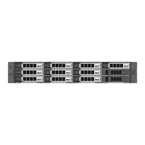
After installing the hardware in a rack and connecting power and network cables, you can deploy each OmniCube server into a SimpliVity Federation. As your capacity and performance needs increase, you can add more OmniCube servers for easy, on-demand scalability, with no disruption to users. - Page 9 Figure 2: OmniCube CN-2000 and CN-3000 front panel Figure 3: OmniCube CN-2200 front panel Table 1: Front panel component descriptions Callout Component Description Power button Controls power to the system and indicates whether there is power to the system. If the indicator is green, the system is receiving power.
-
Page 10: About The Back Panel Components
Callout Component Description Storage The disk drives have power (top) and activity (bottom) LED indicators. Labels indicate the type (SAS or SATA) and capacity of each drive. For rotational drives, the rotation speed (rpm) is indicated. The system models contain different drive configurations: ■... - Page 11 Figure 5: Back panel of an OmniCube server with two CPUs Table 2: Back panel component descriptions Callout Component Description Riser 1 Contains PCIe slots 1-3. You can install optional 2x10GbE or 2x1GbE network cards in these slots, as shown in slot 2, used by guest VMs only. A system with a single CPU does not contain riser 1.
-
Page 12: Environmental And Technical Specifications
10GbE ports Two 10GbE network interfaces, numbered 1 and 2. Each 10GbE interface has link (top) and activity (bottom) round LEDs. These interfaces are dedicated to SimpliVity Storage and Federation networks. 1GbE ports Two 1GbE network interfaces, numbered 3 and 4, from left to right. -
Page 13: Power And Thermal
Dimension Centimeters Inches Maximum depth (from rack 75.58 29.75 flange) System Model Kilograms Pounds CN-2000, CN-2200, CN-3000 32.5 71.5 CN-5000 29.5 Power and thermal OmniCube servers have two redundant power supplies with specific power and thermal specifications. Specification CN-2000 and CN-3000 CN-2200 CN-5000 ■... -
Page 14: Temperature And Humidity
Temperature and humidity OmniCube servers have limits for temperature and humidity under operating and storage conditions. Specification Description Humidity and 10°C to 35°C (50°F to 95°F) at 10% to 80% relative humidity with 26°C (78.8°F) Temperature maximum dew point (maximum wet bulb temperature). De-rate maximum (continuous allowable dry bulb temperature at 1°C per 300m above 950m (1°F per 547 ft operation) -
Page 15: About Hardware Upgrades
■ FCC 47 CFR Part 15 Subpart B: 2012 ■ EN 55022:2010 COR 2011 ■ CISPR 22:2008 ■ EN 55024:2010 ■ CISPR 24:2010 ■ COR 2011 ■ VCCIV3:2009 ■ ANSI/UL 60950-1, 2nd Edition (2007) ■ CSA C22.2 No. 60950-1 2nd Edition (2007) ■... -
Page 16: Chapter 2: Install The Server Hardware
■ The OmniCube servers are heavy. You must have at least one other person to help you lift and unpack the carton, and SimpliVity recommends the use of a datacenter equipment lift. ■ You have cut the pallet shipping straps, which might have considerable tension, using an appropriate tool and safety wear. - Page 17 LED extension cable, and the installation instructions. Do not open this box until the end of the installation procedure, when you are ready to organize the system cables. 6. Remove the accessory pack (callout 3), which contains: ■ SimpliVity bezel. ■ Power and network cables. ■ Software and documentation flash drive.
-
Page 18: Shipping Carton Contents
7. If you are not ready to install the system in a rack, keep it in the shipping box or place it on a sturdy surface that is protected from electrostatic discharge. Shipping carton contents The shipping carton contains some standard items while other items are included based on your configuration. - Page 19 Hardware Description Application An optional third cable is only if you are connecting the required to use the IPMI port for 1GbE network interfaces on remote console access. each server to a switch, such as in a direct connected or switch- connected network configuration, for example.
-
Page 20: Install The Server Enclosure In A Rack
■ Install the servers in a rack starting from the bottom of the rack. ■ Always install the servers in a horizontal position, or you void your warranty and support contract. Install the server enclosure in a rack You install the rails, which are included in the shipping carton, at the lowest available U space in the rack enclosure. -
Page 21: Mount The Enclosure In The Rails
Note: The blue bracket latches will not close properly if the front and rear rail brackets are not level. Make sure that both rails are level, and that they occupy the same U location in the rack. Next steps You can now mount the system enclosure in the rails. Mount the enclosure in the rails It takes two people to install each system into the rails, one person on either side, each holding the system enclosure at the front and rear. -
Page 22: Connect The Network Cables
Network interfaces 1 and 2 are 10GbE and network interfaces 3 and 4 are 1GbE. Procedure overview Read the following information before performing the procedure. For information about the ports required by SimpliVity servers, see the SimpliVity OmniStack Host Deployment Guide. Figure 9: OmniCube host network ports The other networking interfaces are: ■... -
Page 23: Connect The Power Cables
You connect both power supplies to power sources. Procedure overview For high availability, you can connect each power supply to a different circuit. In addition, SimpliVity recommends that you use redundant uninterruptible power supply (UPS) systems to protect against a complete power outage. -
Page 24: Organize The Cables
You can now connect the network cables. Organize the cables Procedure overview If you do not want to use the cable management arm (CMA), use the two hook and loop straps provided in the rail kit to organize the power and network cables. Note: Make sure you have sufficient slack in the cables to fully extend the enclosure from the rack until the rails are safely locked in the extended position. - Page 25 Procedure 1. Identify the front panel mounting lugs on the right side of the system. Figure 12: OmniCube Bezel Lugs 2. Insert the bezel tabs into the front panel mounting lugs. Figure 13: OmniCube Bezel Tabs 3. Rotate the left side of the bezel inward toward the front panel and push firmly until you hear the latch click and engage.
-
Page 26: Detach The Omnicube Bezel
Figure 14: Securing the OmniCube Bezel Detach the OmniCube bezel You can detach the OmniCube bezel from the front panel of the system to gain access to the front drives. Procedure 1. Hold the blue cube handle to detach the bezel and push up on the release latch. Figure 15: OmniCube Bezel Latch 2. -
Page 27: Chapter 3: Configure The Ipmi Port For Remote Management
This procedure assumes you are using a computer with Microsoft Windows. If you prefer to configure IPMI at a later time, you can skip this task and proceed with deploying an OmniCube host using Deployment Manager. See the SimpliVity OmniStack Host Deployment Guide. Procedure Connect an Ethernet cable from the Ethernet port on the laptop to the IPMI Ethernet port on the rear of the OmniCube server. -
Page 28: Connect To Ipmi And Launch The Virtual Console
You can optionally change the default IPMI password if prompted to do so, according to your sitespecific security requirements. Click iDRAC Settings > Network in the left panel. Check the box for Enable IPv4. Do one of the following: ■ Check the box for Enable DHCP. ■... -
Page 29: Ipmi Configuration Requirements
■ If you use DHCP to assign an IP address instead of using a static IP, SimpliVity recommends that you check the option Register RAC on DNS and use the DNS RAC to reference the OmniCube host. -
Page 30: Chapter 4: Server Troubleshooting
Chapter 4: Server troubleshooting This section contains the following topics: • About diagnostic indicators • About drive monitoring • About power supply monitoring • About Accelerator card monitoring • About network interface monitoring You can use the diagnostic indicators and LEDs to identify problems with the server hardware. For assistance with resolving hardware problems, such as a component failing, contact Customer Support. -
Page 31: About Drive Monitoring
Callout Description Temperature indicator. The indicator flashes amber if the system experiences a thermal error. For example, a temperature is out of range or fan fails. Memory indicator. The indicator flashes amber if a memory error occurs. Drive indicator. The indicator flashes amber if a drive fails. Green indicates normal operation. -
Page 32: About Front Drive Numbering
Table 4: Drive status LED Pattern Drive Status Description Flashes green two times per second Identifying the drive or preparing the drive for removal. Drive ready for removal, or all drives are initializing. The drive status LED remains off while the drives are initializing after the system is turned on. -
Page 33: About Power Supply Monitoring
Figure 19: CN-2200 drive numbering The drives are numbered from 0 to 9, top to bottom, and left to right. Drives 0 and 1 are SSDs and drives 2 to 9 are HDDs. Drives 10 and 11 are empty. Figure 20: CN-3000 and CN-5000 drive numbering The drives are numbered from 0 to 23, left to right. -
Page 34: About Accelerator Card Monitoring
Table 6: Power supply LED States State Off: Indicates no power present. Steady green: Indicates the power supply is connected to a power source, is operational, and is supplying power to the system. Flashing yellow: Indicates a problem with the power supply. Flashing green: When performing a hot swap of a power supply, with the system powered on, this LED indicates that the newly-installed power supply is not compatible with the installed power supply. -
Page 35: Accelerator Card Is Not Detected
Server state LED 1 LED 2 Description Field Programmable Flashing red (1 on, 1 Gate Array (FPGA) off) configuration error or configuration failed. FPGA configuration is Steady green complete. Firmware is not Flashing red (2 on, 2 responding to health off) check. -
Page 36: Revert An Accelerator Card To Its Backup Firmware
1. In your hypervisor management interface, locate the OmniCube host or OmniStack host with the problem Accelerator card. 2. Shut down and power off the server as explained in the SimpliVity OmniStack Administrator Guide. 3. Wait three minutes until both LEDs have stopped glowing, which indicates that the capacitors on the Accelerator card have fully discharged. - Page 37 Figure 23: Network interface LEDs The image above displays the following interfaces: ■ Network interfaces 1 and 2 are 10GbE (callout 1). ■ Network interfaces 3 and 4 are 1GbE (callout 2). Table 9: 10GB interface LED states Link Status (top LED) Activity Status (bottom LED) Description No network connection.
- Page 38 Link Status (left LED) Activity Status (right LED) Status Description Sending or receiving network Flash green data. Chapter 4: Server troubleshooting...
-
Page 39: Chapter 5: Drive Maintenance
Chapter 5: Drive maintenance This section contains the following topics: • Drive maintenance guidelines • Remove a drive • Install a drive If a disk drive fails, replace it as soon as possible. Drive maintenance guidelines ■ You can replace a single failed or failing drive without disrupting operations. ■... -
Page 40: Remove A Drive
For more information about how to complete the tasks, see the SimpliVity OmniStack Administrator Guide Remove a drive You remove a hard disk drive (HDD) or solid state drive (SSD) that has failed, or is failing, to replace it with a new drive. Replace a problem drive as soon as possible. -
Page 41: Install A Drive
6. Place the drive on a surface that is protected from electrostatic discharge. 7. Install the replacement drive or a drive filler. Install a drive You install a drive to replace a failed, or failing, hard disk drive (HDD) or solid state drive (SSD). You can also install a drive filler, since the drive bay cannot be empty after the failed drive is removed. - Page 42 4. Orient the drive properly. 5. Grasp the edge of the plastic drive carrier and slowly insert the drive into the slot, stopping when you feel resistance. 6. Simultaneously rotate the handle upward and press the drive completely into the slot. 7.
-
Page 43: Chapter 6: Power Supply Maintenance
Chapter 6: Power supply maintenance This section contains the following topics: • About power supply maintenance guidelines • Remove a power supply • Install a power supply Each server has two hot-swappable power supplies. If a power supply fails, replace it as soon as possible. -
Page 44: Install A Power Supply
Note: Do not leave a power supply slot empty. Do not remove a failed power supply unless you have a replacement power supply that is ready to install. Procedure 1. Identify the failed power supply. 2. Disconnect the power cable from the power supply. 3. - Page 45 3. Slide the power supply into the empty slot until you hear the latch engage. 4. Ensure that the power supply is fully inserted and locked in by the orange, spring-loaded clip. 5. Connect and secure the power cable to the new power supply. 6.
-
Page 46: Chapter 7: About Network Cabling Options
About the direct-connected network configuration • About the switch-connected network configuration There are different options for cabling the 10GbE and 1GbE interfaces used for the SimpliVity networks: Storage, Federation, and Management. You select the configuration that best meets the needs of your environment. -
Page 47: About The Direct-Connected Network Configuration
■ For each system, use two SFP+ Direct Attach active cables (or Fiber Optic cables) to connect the 10GbE ports to different 10GbE switches. ■ Separate the SimpliVity Storage, Management, and Federation networks by using VLANs on each switch. About the direct-connected network configuration A direct-connected network configuration for a Federation with two OmniCube servers uses the 10GbE connections for the SimpliVity Storage and Federation networks. -
Page 48: About The Switch-Connected Network Configuration
About the switch-connected network configuration The switch-connected network configuration for a Federation with two OmniCube servers uses redundant connections to 10GbE switches for the SimpliVity Storage and Federation networks. It uses redundant 1GbE connections to 1GbE switches (shown below) or, optionally, 10GbE connections to 10GbE switches for the Management network. - Page 49 Figure 28: Switch-connected Storage network configuration Configuration guidelines: ■ For each system, use two SFP+ Direct Attach active cables (or Fiber Optic cables) to connect the 10GbE network interfaces to different 10GbE switches. ■ For each system, use two network cables to connect the 1GbE network interfaces to different 1GbE switches.
-
Page 50: Appendix A: Simplivity Terminology
A collection of SimpliVity OmniStack hosts that share resources and provide high availability and load-balancing services. failure domain A collection of SimpliVity OmniStack hosts that that serve as potential high availability failover targets for each other for purposes of high availability and disaster recovery. - Page 51 (Previously referred to as an OmniCube Virtual Controller.) SimpliVity Arbiter The SimpliVity software that facilitates communication between OmniStack hosts in a Federation and enables failover and recovery operations. The Arbiter casts a tie-breaking vote in datacenter or cluster failure scenarios that include an even number of OmniStack hosts.
Need help?
Do you have a question about the OmniCube CN-2000 and is the answer not in the manual?
Questions and answers