
Subscribe to Our Youtube Channel
Related Manuals for Epcos BR 7000

Summary of Contents for Epcos BR 7000
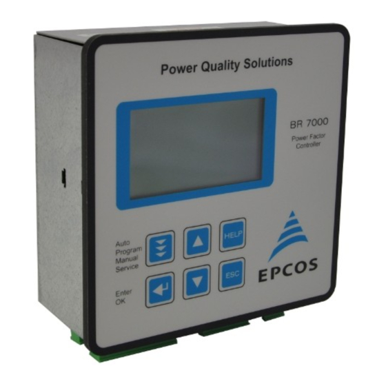
- Page 1 Power Factor Controller BR 7000 Power Quality Solutions AUTO-MODE 2/2 kvar BR 7000 Power Factor Controller Auto Program HELP Manual Service Enter Manual Version 1.1 E...
- Page 2 CAUTIONS: 1. High voltage ! 2. BR7000 may only be used indoor ! 3. Make sure that the discharge time set in the controller matches the capacitor discharge time !
-
Page 3: Table Of Contents
CONTENTS Section 1 General Section 2 Installation and instructions for usage Section 3 Connection alternatives measuring voltage and measuring current Section 4 Display functions Section 5 Display of grid parameters Section 6 PROGRAM-MODE / Manual programming p.11 6.1 Programming lock p.18 6.2 QUICK-Program p.19... -
Page 4: General
Section 1: GENERAL The power factor controller BR7000 is the consequent follow-up development of the well proven series BR6000. The main distinctive feature is the new 3-phases measuring system. Due to the 3-phases recording of voltage and current the device allows a convenient usage as grid measuring device and as power factor controller. -
Page 5: Installation And Instructions For Usage
Section 2: INSTALLATION AND INSTRUCTIONS FOR USAGE The BR7000 is designed as panel mounting instrument in PFC-systems. This requires a cut out of 138 x 138 mm according to DIN 43700 / IEC 61554. The controller has to be inserted from the front and fixed with the clamps (included in delivery). The device may only be installed by qualified personnel and may only be operated according the given safety regulations. - Page 6 5A or 1A (programmable). A voltage converter is required for different operating voltages. Caution! Voltages which exceed the allowed voltage range can damage the device ! BR 7000 front view Power Quality Solutions Operating mode: Increase HELP...
-
Page 7: Connection Alternatives Measuring Voltage
Section 3: CONNECTION ALTERNATIVES MEASURING VOLTAGE AND MEASURING CURRENT According to the existing grid and the desired operating mode (CONTROL-MODE Programming) the BR7000 has to be connected accord. one of the following alternatives. In grids without neutral conductor the connector N(PE) from meas.voltage at the controller has to be connect with the PE of the grid ! Alternative 1: measuring performed in each phase - 3 current transformers needed Use: CONTROL-MODE: 1 - 4 (control modes see page 11) - Page 8 HIGH VOLTAGE LOW VOLTAGE Meas- supply Meas.current 20 kV / 400 V voltage voltage Im (X/1A) L1 (R) L1 (R) L2 (S) L2 (S) L3 (T) L3 (T) 20000 BR 7000 Meas.current Meas. voltage Um Supply voltage Ub - 7 -...
- Page 9 Section 4: DISPLAY - FUNCTIONS After the operating voltage has been switched on, the BR7000 briefly indicates with description and software-version before changing to automatic operation. Actual values and symbols of the particular operation state are shown in the display. In the automatic operation (standard) capacitor steps are automatically switched on or off to reach the pre-set target cos-phi.
- Page 10 Section 5: DISPLAY OF GRID PARAMETERS 5.1 Display of 3 selected grid parameters In Auto-Mode, button é leads to display mode 1. Here 3 (free selectable) grid parameters are displayed in large letters. The selection and storage of these values is done in the Display- Editor.
-
Page 11: Display Functions
=== DISPLAY === Examples of different displays: DISPLAY 1/3 DISPLAY 1/3 ANZEIGE 1/3 DISPLAY 1/2 1 LINE VOLTAGE APPAR.CURRENT REACTIVE POWER 233 V 235 A 71 kvar L1-N 233 V 133 A 23 kvar L2-N 233 V 133 A 22 kvar L3-N 24 V 116 kvar... - Page 12 Section 6: PROGRAM-MODE (manual programming) Pressing the button “Operation Mode“ one time switches from automatic operation to the program mode. The upper part of the display always shows the parameter, the adjustable values are shown in the lower part. Editable values are generally given in square brackets. Changes of these values can be done by the buttons é...
- Page 13 === PROGRAM-MODE === CONTROL-MODE [2]: MIXED-MODE 3-phasige measuring 3 current transformers required. Values displayed and calculated per phase. Connection of measuring current and measuring voltage see page 6. Controlling done with max. 4 outputs per phase for switching of single phase capacitors L-N. The rest of the outputs (min.
- Page 14 === PROGRAMM-MODE === CONTROL-MODE [4]: 3-phase measuring / max. 15 three-phase capacitors 3 current transformers required. Connection of measuring current and measuring voltage refer to page 6. Values displayed and calculated per phase. Controlling done with max. 15 outputs according to maximum or mean-value of the reactive power CONTROL-MODE [5]: 1-phase measuring / max.
- Page 15 === PROGRAMM-MODE === 3 I-CONVERTER PRIM [1000 ] A / X ( 5 ... 13000) A PROGRAM-MODE Selects the primary current of the current converter. 3 I-CONVERTER PRIM Sequential adjustment of L1...L3. [ 1000]A / 5 A via the é / ê keys. Save and continue with ENTER 1000]A / 5 A 1000]A / 5 A 4 I-CONVERTER SEC...
- Page 16 === PROGRAM-MODE === 9 TARGET COS PHI [ 0.98 ind ] ( 0.3 ind ... 0.3 cap ) PROGRAM-MODE TARGET cos j By setting the target cos phi, the power factor to be attained via the PF correction is defined. Sequential setting of L1 ...
- Page 17 === PROGRAM-MODE === 18 DISCHARGE TIME: [ 60 ] sec. ( 1 sec..20min.) PROGRAM-MODE 18 DISCHARGE TIME This is the time for which an individual output is blocked C-ON 40 s between disconnecting and connecting. It depends on C-OFF 40 s C-DIS...
- Page 18 === PROGRAM-MODE === 22 EXTERNAL INPUT [ NO ] ( 1...5 ) PROGRAM-MODE 22 EXT. INPUT [2] Setting of the desired action upon applying a control voltage of 110...230V~ at the external input. [ 2.PARAMETER SET] 1 - NO (no action) 2- 2nd parameter set (switch over to 2nd parameter set).
-
Page 19: Programming Lock
=== PROGRAM-MODE === 38 CLOCK [ HH:MM ], DATE [DD.MM.YY] PROGRAM-MODE 38 CLOCK Set system-time and date (Due to an internal battery the time will be kept even in [ 15]: 27 case of power loss) MONDAY 05.03.2013 Selection with é / ê. Save/continue with ENTER 39 CONTRAST [ 6 ] ( 0...10) -
Page 20: Quick-Program
Section 6.2: QUICK-PROGRAM The QUICK-PROGRAMM-MODE can be activated from the menu ”PROGRAMMING“ by pressing the button “é" and is used for fast programming of the BR7000. The list hereafter contains the most important parameters for programming in short form. For most applications the input of these values is already sufficient. Input is done like for normal programming: 1 CONTROL-MODE [1...6]... -
Page 21: Automatic Initialization
Section 7: AUTOMATIC INITIALIZATION Automatic initilization is used for the automatic recognition of parameters in the compensation system by the BR7000, for plausibility check and for saving of these parameters. The customer has to make very few adjustments only, if at all. Activating is done in menu point “PROGRAMMING”... -
Page 22: Automatic Test Run
Section 8: AUTOMATIC TEST RUN The automatic test run is used for automatic check and comparison of the parameters already programmed in the BR7000 with the measured values of the PFC-system (plausibility). Discrepancies will be displayed in plain text. Activation is done from menu “PROGRAMMING”... - Page 23 === Actual assignment of outputs === Example: CONTROL-MODE 2 (MIXED-MODE) set in END STOP to: 4 stages with 3 single- phase capacitors each and 3 stages with 1 three-phase capacitor each 3 x 4 single-phase capacitors 3 standard- 3-phase capacitors L1 (R) L2 (S) L3 (T)
-
Page 24: Manual Operation
Section 10: MANUAL OPERATION Manual operation is designed for maintenance and service purpose. Menu “MANUAL-MODE” consists of the following sub- windows: MANUAL CONTROL [STOP] L1 ( L1...L3) MANUAL-MODE 1 MAN.OPERATION manual operation, capacitor steps connected /disconnected according to the control 0.983 IND series and switching time irrespective of the prevailing [SWITCH ON ]... - Page 25 Section 11: SERVICE MENU / Fault memory This service menu can be reached by the operating-mode key. The stored maximum values of the grid parameters can be displayed here as well as the number of switching operations of the individual capacitor steps and their operation time. The desired stage (in square brackets) is selected via the arrow keys.
-
Page 26: Expert Mode
Section 12: EXPERT-MODE 1 and 2 The expert modes are meant for the adjustment of values which normally should not be changed. As a protection these levels have access codes: EXPERT-MODE PASSWORD: ExpertMode 1: “6343” PASSWORD ???? ExpertMode 2: “2244” 0*** 12.1 EXPERT-MODE 1 (Code: 6343) 1 BASIC SETTINGS NEW... - Page 27 === EXPERT-MODE === 10 C-TEST [YES] ( YES/NO) During each switching operation in AUTO-MODE the power of the particular capacitor stage is calculated and compared to the step power of the capacitor stage. An error message will be displayed in case of discrepancies! (Display as inverse capacitor-symbol) This test can be suppressed here.
-
Page 28: Expert-Mode
12.2 EXPERT-MODE 2 ( Code: 2244 ) The 2nd expert mode defines all operation-, warning- and fault messages which can be displayed by the BR7000. They can be activated/de-activated separately. When de- activated, the display of the message as well as the possible activation of the alarm-relay or consequent effects on the control behavior are suppressed. -
Page 29: Expert-Mode
Section 13: CONTROL PRINCIPLE The control behavior can be selected in the programming mode. Generally, the BR7000 offers different possibilities of controlling: ˜ SEQUENTIAL CONNECTION In sequential connection, the required capacitor stages are successively connected or disconnected step by step (last in first out).The ranking of each step always corresponds to the power of the smallest stage. -
Page 30: Interfaces
Section 14: INTERFACES As a standard, the BR7000 is equipped with two isolated RS485 interfaces according to the following assignment: Interface 1 Interface 2 ext. Input Switch Termination Gnd B 230V~ n.c. View from bottom : ( L1) ( N ) N(PE) Supply voltage Ub Meas.voltage Um... -
Page 31: 14.2 Controller Coupling
(First all stages of the first system, then all steps of the second system) Coupling of 2 power factor controllers BR7000 is done via their system interface: Power Quality Solutions Power Quality Solutions Interface 2 Interface 2 BR 7000 BR 7000 Power Factor Power Factor Controller Controller Auto... -
Page 32: Windows-Software For Pc
14.3 Windows-Software for PC (enclosed with delivery) Windows-Software for programming of the PF-controller BR7000 and for visualization, storage and analysis of grid parameters. Connection to RS485-Bus Administration of several controllers possible Direct connection to USB-port of PC via accessory USB-adapter It allows a comfortable visualization and analysis of grid parameters during online- operation. -
Page 33: Alarm Relay / Error Messages
Section 15: ALARM RELAY / ERROR MESSAGES The contact of the alarm relay (K21) is closed during normal operation and opens in case of failure. At the same time, the respective error is indicated in plain text in the display: UNDER COMPENSATED - display and relay missing reactive power... -
Page 34: Annex 1 Troubleshooting
Annex 1: Troubleshooting Fault Reasons / Solution For target cos PHI=1 and inductive load Check terminals of measuring voltage and steps are switched out / for the already measuring current (l and k)! compensated grid steps are switched in Check phase position! Supply and consumption Check phase allocation exchanged. - Page 35 Fault Reasons / Solution In inductive grid stages are switched In case a value other than 1 for target- cos-phi is off resp. in capacitive grid conditions pre-set, the display “<” may be illuminated stages are switched on despite an inductive grid load. Arrows indicate the control direction, not the grid conditions! The controller does not connect all Check END STOP!
-
Page 36: Annex 2 Technical Data
Annex 2: Technical Data Type series BR 7000..Operating voltage 110...230 V~, +/-15%, 50 / 60Hz Measuring voltage (3-phase) 3 · 30...440 V~ (L-N) / 50...760V~ (L-L) Measuring current (3-phase) 3 · X : 5 / 1A selectable Power consumption <... - Page 37 Display / Display functions Display of grid parameters 3-phase As real value/in %/as bar graph cos-Phi, voltage, current, frequency, reactive-, active-, apparent power, missing kvar, temperature, THD-U / THD-I Large display of 3 grid parameters selection via display-editor Harmonics 3. - 31. harmonics of U and I display also in % or as bar graph Osci-mode graphical display of 1 period U/I in oscilloscope...
-
Page 38: Annex 3 Factory Settings
Annex 3: Factory settings Note: The following values for the default settings apply only if the controller is supplied directly from the manufacturer. Otherwise, these values may have been replaced by settings made by the manufacturer of the compensation system (optimal values for the relevant network) Parameter Default setting... - Page 39 Parameter Default setting programmed values of this 2nd parameter set / system (to be entered by EXPERT-MODE manufacturer or operator) Values 2nd parameter set Default values are the same as in the 1st parameter set. Expert-Mode: Code Expert-Mode 1 6343 Cannot be changed 2244 Cannot be changed...
-
Page 40: Annex 4 Control Series Table
Annex 4: Table of control series Control serie Loop connection 1 : 1 : 1 : 1 : 1 ..possible 1 : 2 : 2 : 2 : 2 ..possible 1 : 2 : 3 : 3 : 3 ..possible 1 : 2 : 3 : 4 : 4 .. - Page 41 Annex 5: MODBUS-Protocol - Part 1: read-only registers ( Functioncode 3 ) Note Modbus No. Register / Function Range Unit / Digit Voltage L1 16 Bit 16 Bit Current L1 Frequency L1 16 Bit 1 Hz Temperature (cabinet) 16 Bit 1 °C 3001 16 Bit...
- Page 42 Annex 5: MODBUS-Protocol - Part 2: read-only registers ( Functioncode 3 ) Note Register / Function Range Unti / Digit Modbus No. Min. Voltage L1 16 Bit 3276 16 Bit Min. Voltage L2 3277 Min. Voltage L3 16 Bit 3278 Max.
- Page 43 Annex 5: MODBUS-Protocol - Part 3: Read-/ Write-registers ( Functioncode 3 / 6 ) Modbus HIGH-Byte Range LOW-Byte Range Modbus Register / Function No. 3 No. 6 Register / Function ------ Remote: 0= remote off, 1= switching- 8 Bit Remote-control: max. switching 1 - max power (multiple of 1st step power) 8 Bit...
- Page 44 AUTO-MODE 1/2 0.869 IND 0.869 IND 0.869 IND ===== PROGRAM-MODE ===== 1 2 3 4 Button “UP” branches from programming into - QUICK-PROGRAM - AUTO-INIT LINE VOLTAGE LANGUAGE [ 2 ] - TEST-RUN QUICK-PROGRAM L1-N 230 V L2-N 230 V [ ENGLISH ] L3-N 230 V...
-
Page 45: Control Series Editor
If not needed they are not displayed. 0 INITIALIZATION 1 TEST MEAS.VOLTAGE 2 TEST I-TRANSFORMER 3 TEST MEAS.CURRENT 4 TEST CAPACITOR C1 ... C15 Operating diagram (Brief programming) Power Factor Controller BR 7000 (V1.1) - 44 -... - Page 46 == SERVICE == ===== EXPERT-MODE 1 ===== 1 min/max VOLTAGE PASSWORD ???? L1-N 230 / 235 V 0 * * * (6343) L1-N 230 / 235 V L1-N 230 / 235 V max CURRENT C - POWER 1 BASIC SETTINGS 13 TEST ATTEMPTS 123 A [C01] -->...
- Page 47 ===== EXPERT-MODE 2 ===== = OSCI-MODE = =DISPLAY EDITOR= PASSWORD ???? 1 DISPLAY LINE 1 1 [ REACTIVE PWR 0 * * * (2244) 2 ACTIVE PWR 3 APPARENT PWR S 1 HARMONICS 5 OVERVOLTAGE 2 DISPLAY LINE 2 1 [ REACTIVE PWR 3.
- Page 48 Accessories Universal-Measuring Devices MMI 6000 MMI 7000 DataLog SD for recording data of BR6000 / BR7000 RJ45-adaptor connect several devices to a RS485-Interface via LAN-cable...
Need help?
Do you have a question about the BR 7000 and is the answer not in the manual?
Questions and answers