Table of Contents
Advertisement
Quick Links
Advertisement
Table of Contents

Related Manuals for Sega Initial D4


Summary of Contents for Sega Initial D4
- Page 2 BEFORE USING THE PRODUCT, BE SURE TO READ THE FOLLOWING: To maintain safety: To ensure the safe operation of this product, be sure to read the following before usage. The following instructions are intended for the users, operators and the personnel in charge of the operation of the product.
- Page 3 SEGA. INSPECTIONS IMMEDIATELY AFTER TRANSPORTING THE PRODUCT TO THE LOCATION Normally, at the time of shipment, SEGA products are in a status allowing for usage immediately after transporting to the location. Nevertheless, an irregular situation may occur during transportation.
-
Page 4: Table Of Contents
TABLE OF CONTENTS BEFORE USING THE PRODUCT, BE SURE TO READ THE FOLLOWING: TABLE OF CONTENTS ..................i INTRODUCTION ....................iii HANDLING PRECAUTIONS ..............1 PRECAUTIONS REGARDING INSTALLATION LOCATION ....2 2-1 LIMITATIONS OF USAGE ...................2 2-2 OPERATION AREA .....................3 PRECAUTIONS REGARDING PRODUCT OPERATION ...... - Page 5 CONTROL PANEL .................. 35 9-1 OPENING THE CONTROL PANEL ................35 9-2 ADJUSTING/REPLACING THE VOLUME..............36 9-3 GREASING ........................38 9-4 STOPPER RUBBER REPLACEMENT ..............38 9-5 REPLACING THE INPUT SWITCH BOARD .............39 SHIFT LEVER ................... 41 10-1 REMOVING THE SHIFT LEVER ................41 10-2 GREASING ......................42 ACCELERATOR &...
-
Page 6: Introduction
"IMPORTANT" and the symbol below. Indicates important information that, if ignored, may result in the mishandling of the product and cause faulty operation or damage to the product. Sega Amusements U.S.A., Inc. 800 Arthur Avenue, Elk Grove Village, IL 60007-5215, U.S.A. TEL:... - Page 7 Defi nition of 'Site Maintenance Personnel or Other Qualifi ed Individuals' Procedures not described in this manual or marked as ‘to be carried out by site maintenance personnel or other qualifi ed professionals’ should not be carried out by personnel without the necessary skill or technology. Work carried out by unqualifi...
-
Page 8: Handling Precautions
● Some parts are not designed and manufactured specifi cally for this game machine. The manufacturers may discontinue, or change the specifi cations of such general-purpose parts. If this is the case, SEGA cannot repair or replace a failed game machine whether or not a warranty period has expired. -
Page 9: Precautions Regarding Installation Location
BACK SIDE PRECAUTIONS REGARDING INSTALLATION LOCATION ● This product is an indoor game machine. Do not install it outside. Even indoors, avoid installing in places men- tioned below so as not to cause a fi re, electric shock, injury and/or malfunction. - Places subject to rain or water leakage, or places subject to high humidity in the proximity of an indoor swim- ming pool and/or shower, etc. -
Page 10: Operation Area
● Be sure to provide suffi cient space specifi ed in this manual. Do not allow objects to block the ventilation ports. It can cause generation of heat and a fi re. ● SEGA shall not be held responsible for damage, compensation for damage to a third party, resulting from the failure to observe this instruction. -
Page 11: During Operation (Paying Attention To Customers)
3-2 DURING OPERATION (PAYING ATTENTION TO CUSTOMERS) To avoid injury and trouble, be sure to constantly give careful attention to the behavior and manner of the visitors and players. ● For safety reasons, do not allow any of the following people to play the game. - Those who need assistance such as the use of an apparatus when walking. -
Page 12: Part Description
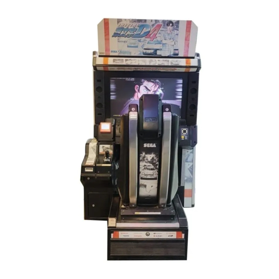
PART DESCRIPTION BILLBOARD PANEL CARD READER/WRITER LCD DISPLAY CONTROL PANEL SEAT ASSY COIN DOOR CASHBOX DOOR ACCELERATOR AND BRAKE SHIFT LEVER... -
Page 13: Accessories
DVD SOFTWARE KIT (1) (Power cable and USB MINI cable) are sold separately. (Only you need when software update...etc) The DVD DRIVE and DVD harness that come with SEGA’s “The House of the Dead 4” are compatible with this product. KEY CHIP (1) -
Page 14: Assembly And Installation
ASSEMBLY AND INSTALLATION ● The work described below should be carried out by the site maintenance personnel or other qualifi ed profession- al. If there are no personnel available with the necessary knowledge or skills, send a job request to the contact listed in this document. -
Page 15: Installing The Cabinet
6-1 INSTALLING THE CABINET 6-1-1 ATTACHING THE POP Use three screws to fasten the POP to the cabinet. Use a step when carrying out this procedure. 8-32 x1/2" Phillips Truss head Black (7) 6-1-1 FIG. 01 6-1-2 SECURING IN PLACE Be sure to ground the adjusters, and secure the product fi... -
Page 16: Refilling The Cards
6-1-3 REFILLING THE CARDS ● Be sure to use the product’s dedicated cards. Using any other cards may cause the product to malfunction or become damaged. ● Be sure to adhere to the assigned procedures, orientation, and quantities when loading the cards. - Page 17 Refi ll the Initial D4 IC cards. Place the cards in the orientation shown in the diagram, loosen them, and load 100 cards. Do not load more than 101 cards, as this may result in damage to the product or malfunctions.
-
Page 18: Connecting Network Cables
6-1-4 CONNECTING NETWORK CABLES Use LAN cable in cash box to connect 2 games. Open the back door of cabinet. True LAN cable as bottom slit of cabinet. PASS LAN CABLE Like this... SLIT FOR LAN CABLE Connect to the other Main PCB on other cabinet. -
Page 19: Turning On The Power
6-2 TURNING ON THE POWER YOU DO NOT NEED DVD DRIVE BECAUSE ID4 GAME IS INSTALLED GAME SOFTWARE ALREADY AT MANUAFACTURE. PLEASE REFER BELOW SECTION WHEN YOU NEED FOR MAINTENANCE OR FUTURE UPDATE. ● When connecting the DVD wire connector, check the orientation carefully and connect securely. The connec- tor must be connected in the proper direction. - Page 20 ● Some parts are not designed and manufactured specifi cally for the kit. The manufacturers may discontinue, or change the specifi cations of such general-purpose parts. If this is the case, SEGA cannot repair or replace a failed kit whether or not a warranty period has expired.
- Page 21 ● The software is not installed on the game board (LINDBERGH) when the power supply is engaged, so the “Error 22” message is not a malfunction. However, if there is another error display, or if there is no video output at all, there might have been an error in product assembly, wiring connections might be faulty, or the LINDBERGH might not be functioning properly.
- Page 22 The LINDBERGH startup screen will appear on the monitor. Wait for at least 1 minute. The product will read an error. Confi rm that it is “Error 22.”If this is correct, proceed to the next step. Refer to the this manual and take appropriate action if the product is not in “Error 22”.
-
Page 23: Installation Settings
Set, adjust, and confi rm the following settings in test mode. Refer to the LINDBERG service manual for information on system test mode, and the Initial D4 service manual for information on game test mode. In system test mode, set COIN ASSIGNMENTS as follows. -
Page 24: Card Reader/Writer
CARD READER/WRITER 7-1 SETTING DEDICATED CARDS ● Be sure to use dedicated cards available for this product. Use of ones other than such dedicated cards may cause a malfunction or failure of the machine. ● Be sure to set the specifi ed number of card in the specifi ed orientation by using the specifi... -
Page 25: Cleaning
7-2 CLEANING Always use the designated Cleaning Card. Using anything other than the designated card may cause faulty operation and/or unit failure. The product counts the number of times the game is played and the number of new cards issued. When either the play count or the number of new cards issued exceeds 200, a cleaning reminder is displayed the next time the power is turned off and on again. - Page 26 Cleaning the Stocker Rollers Carry out the following procedure once every 10 days to clean the Stock Rollers. Further, check whether or not the rollers are dirty when refi lling the cards, and clean them if they are dirty. NOTE: Be sure to use a new cleaning card when cleaning the stocker rollers. Enter GAME TEST MODE and select “IC CARD R/W &...
- Page 27 Insert a new cleaning card. Place the retainer on top of the cleaning card. CLEANING CARD 7-2 FIG. 07 7-2 FIG. 06 Select CLEAN STOCKER and press the test button. Roller cleaning will commence. During cleaning “CLEAN- ING STOCKER ROLLER” will display in the UNIT STATUS area, and change to “DONE” when complete. IC CARD R/W &...
- Page 28 Lift the retainer, and remove the cleaning card. Check that the rollers are no longer dirty. NOTE: If the rollers are still dirty, use a new clean- ing card and repeat steps 4 through 6 to repeat the cleaning process. ROLLER 7-2 FIG.
-
Page 29: Clearing Card Jams
7-3 CLEARING CARD JAMS When attempting to perform this operation without powering down so that game play can be restored, exercise extreme caution. Machine parts may move unexpectedly when the power is ON. This may result in fi ngers being caught or severed and other injuries. -
Page 30: Exchanging The Card R/W Unit
7-4 EXCHANGING THE CARD R/W UNIT Remove the truss screws. Use the key to unlock the cover and remove it. Then open back door to remove 6 Nuts to take off hole card reader & Shift box from cabinet. NUTS (6) 7-4 FIG. -
Page 31: Initial D License Restoration Procedure
7-5 INITIAL D LICENSE RESTORATION PROCEDURE If the product fails to renew an Initial D License or an error occurs during the renewal process, you can attempt to restore the license. Refer to the Service Manual and follow the on-screen instructions when restoring a license through the game screen. Restoring in Test Mode Select IC CARD RESTORATION from the GAME TEST MODE screen in Test Mode. -
Page 32: Game Description
GAME DESCRIPTION 8-1 GAME OVERVIEW The game is a car racing game with three different game modes: “Legend of the Streets”, “Time Attack” and “In- store Battle”. The card system allows players to store information such as the cars, wins/loss records and car tune-up status on an Initial D License (IC card). -
Page 33: Game Flow
Race Course Class Area Course Time of day, weather Easy Lake Akina Circular Course/3 laps, Clockwise & Counterclockwise Day/Night, Clear/Rain Normal Myogi One Way, Uphill/Downhill Day/Night, Clear/Rain Hard Akagi One Way, Uphill/Downhill Day/Night, Clear/Rain Hard Akina One Way, Uphill/Downhill Day/Night, Clear/Rain Hard Irohazaka One Way, Downhill/Reverse... - Page 34 My Character Selection Screen If you’re purchasing an Initial D License, you must fi rst select a Character. As you play the game, you will collect Character Parts that you can use to customize your selected Character. 8-2 FIG. 04 Name Entry Screen If you’re purchasing an Initial D License, enter your name (driver’s name) at the player name input...
- Page 35 Change the diffi culty level of “Legend of the Streets” mode. Different Diffi culty: diffi culty levels become available as you clear more races. Race Volume: Adjust the sound volume during races. Voice Volume: Turn rivals’ voices during races on and off. Navigation Display: Turn the in-race navigation screen display on and off.
- Page 36 Continue Screen The Continue Screen appears after 1 Battle (race) in “Legend of the Streets” and “Time Attack” modes, and after the match (or at the end of the alternate mode if no opponent is found) in “In-store Battle” mode. Choose YES and insert the required number of coins to continue playing in the selected mode.
-
Page 37: Mode Overview
8-3 MODE OVERVIEW 8-3-1 Legend of the Streets Game Content & Rules Battle head-to-head against rival characters on 6 different courses. Each checkpoint you pass adds time to the overall time limit. The fi rst one across the fi nish line with the allotted time wins. If you run out of time or cross the fi nish line second, you lose. - Page 38 When you set a new personal best in Time Attack mode using an Initial D License, an Internet Rankings password is dis- played on the screen. Visit the Initial D Internet Rankings webpage (http://initiald.sega.com) and enter this password on to add your best time to the Internet Rakings.
-
Page 39: Initial D License
8-4 INITIAL D LICENSE 8-4-1 Limit on Card Use You can play up to 150 times using the same Initial D License. After that, you must create a new license through the “Initial D License Renewal” process. When you renew, the data from your old license will be transferred to your new one. You keep all the points you’ve collected. - Page 40 8-4-2 Recovery Procedures When an Initial D License Renewal Fails If an error occurs during renewal, follow the procedures listed below the corresponding error message to restore. Should you be unable to restore even after following these steps, try restoring using the IC CARD RESTORATION op- tion in GAME TEST mode.
- Page 41 An error occurs when inserting the new license One of the following error messages is displayed. ● The inserted card is stuck <Card Error> An error occurred when authenticating an Initial D license. The card is stuck. /403 If the cabinet fails in ejecting the card automatically, the normal stuck card error message is displayed and the restoration process is aborted.
-
Page 42: Control Panel
CONTROL PANEL ● In order to prevent an electric shock and short circuit, be sure to turn power off before performing work by touch- ing the interior parts of the product. ● Be careful not to damage the wires. Damaged wires may cause electric shock or short circuit. ●... -
Page 43: Adjusting/Replacing The Volume
Remove all four hexagonal bolts that secure the control panel. Do this carefully, as the control panel will open when the bolts are removed. HEX BOLT (4) 9-1 FIG. 02 Slowly open the control panel, making sure it is fully supported as you do so. Be careful that your hands or feet do not get caught between the panel and game unit. - Page 44 Center the steering wheel, and engage the gear while making sure that the D-cut fl at edge of the volume axis is aligned in the direction indicated (see 9-2 FIG. 01). Tighten the two screws and secure the VR base. Turn the steering wheel and check that the gears move smooth- ly.
-
Page 45: Greasing
Remove the nuts that secure the VR bracket, and detach the volume from the VR bracket (see 9-2 FIG. 04). Using wire cutters or a knife, remove the heat-shrinkable tubing that covers the soldered parts. Melt the solder with a soldering gun, and detach the volume from the wires. Cover each wire separately with the heat-shrinkable tubing. -
Page 46: Replacing The Input Switch Board
Remove the 4 bolts, then remove stopper holder (TFF-2511). STOPPER HOLDER TFF-2511 HEXAGON BOLT (4) M8x40, w/fl at washer 9-4 FIG. 02 9-4 FIG. 01 Remove stopper bolt S (TFF-2507) and the hexagonal socket screw, then replace stopper rubber S (TFF-2508) with the stopper rubber S (TFF-2508-01) that is included in this kit. - Page 47 Detach connector. Detach connector. 9-5 FIG. 03 Remove the four screws and lift the input switch base. SCREW (4) M4x10, w/fl at & spring washers 9-5 FIG. 04 INPUT SWITCH BASE 9-5 FIG. 05 Remove the input switch rubber and board. INPUT SWITCH BOARD INPUT SWITCH RUBBER 838-14707...
-
Page 48: Shift Lever
SHIFT LEVER ● When working with the product, be sure to turn the power off. Working with the power on may cause an electric shock or short circuit. ● Be careful not to damage the wires. Damaged wires may cause an electric shock, short circuit or present a risk of fi... -
Page 49: Greasing
10-2 GREASING Once every three months, apply grease to the indicated parts. We recommend Grease Mate-brand spray grease. (Part No.: 090-0066). Using a socket driver (for M5 screws), remove the two stopper shafts and two fl at washers. Remove the two screws. -
Page 50: Accelerator & Brake
ACCELERATOR & BRAKE ● When working with the product, be sure to turn the power off. Working with the power on may cause an electric shock or short circuit. However, the unit must be switched on when using test mode. Do not touch any part of the unit except those areas indicated. -
Page 51: Greasing
Secure the potentiobase. Confi gure the volume values on the INPUT ASSIGNMENTS screen in Game Test Mode. Check that the values change smoothly in response to pedal input. Replacing the Volume Switch off the unit. Remove the two screws and lift off the potentio cover. Detach the connector from the vol- ume to be replaced. -
Page 52: Test Mode
TEST MODE 12-1 SWITCH UNIT Be sure to move the seat to the rear position before opening the coin chute door. Open the coin chute door, and the switch unit shown will appear. TEST BUTTON SOUND VOLUME SWITCH 12-1 FIG. 01 SERVICE BUTTON TEST BUTTON: Used in TEST Mode. -
Page 53: Input Test
12-3-1 GAME TEST MODE Menu Select GAME TEST MODE from the System Test Menu Screen as follows. Use SERVICE Button to move the cursor to GAME TEST MODE the desired test item. Press the TEST Button to enter the selected item. INPUT TEST OUTPUT TEST After the test is complete, move the cursor to... -
Page 54: Output Test
TESTABLE INPUT DEVICES Steering wheel, pedals (GAS, BRAKE), gear position, Start Button, View Change Button, Directional Buttons (UP, DOWN, RIGHT, LEFT), SERVICE Button, TEST Button. STEERING UP, DOWN, RIGHT, LEFT GEAR POSITION VIEW CHANGE SERVICE TEST START BRAKE 12-3-2 FIG. 02 12-3-3 OUTPUT TEST Select OUTPUT TEST to display the following screen and check the status of each lamp. - Page 55 12-3-4 FORCE FEEDBACK ● When you select “FORCE FEEDBACK”, a connection test runs and the STEERING rotates. ● When the connection check completes, a screen below is displayed, and you may adjust the STEERING resis- tance. ● FORCE: Set the STEERING resistance. The ** indicates the FORCE FEEDBACK current resistance setting.
- Page 56 STEER ADJUSTMENTS Make adjustments to STEERING. Press the TEST Button to display the following screen. Center the STEERING. When the “0” displayed is not STEER ADJUSTMENTS exactly aligned with the “^” mark above CENTER, use the cursor to select RIGHT or LEFT and move the “0” (MIN -40 : MAX 40 ) until it is displayed directly above the “^”...
-
Page 57: Game Assignments
BRAKE ADJUSTMENTS Make adjustments to BRAKE. Press the TEST Button to display the following screen. Set the MAX position by stepping on the BRAKE pedal. The “MAX” display moves to the right depending on BRAKE ADJUSTMENTS how hard the pedal is pressed. (MIN **H : MAX ** H) Entering BRAKE ADJUSTMENTS without having the... - Page 58 Move the cursor to EXIT and press the TEST Button to return to the Game Test Menu Screen. 12-3-7 PASSWORD CONFIRMATION Select PASSWARD CONFIRMATION to display the following screen. When you receive a password notice from SEGA or a sales agent, enter the password here to update product PASSWORD CONFIRMATION specs.
- Page 59 12-3-8 IC CARD R/W & PRINTER TEST ● Be sure to test the operation of the card reader/writer regularly. ● Previous printing may remain on the surface of the card after printing new text or images. This does not affect the data stored on the card. Select IC CARD R/W &...
- Page 60 ● CLEAN ROLLER Clean each type of roller used to deliver cards. Choose this option and UNIT STATUS will display “CLEANING UNIT ROLLER”. Insert a cleaning card to clean each type of roller. When the operation is complete, the cleaning card is ejected. Remove the card to fi nish the cleaning. ●...
- Page 61 ● Screen Display SELECT ACCESS CODE: Select the access code of the card you wish to restore. RESTORE: Restore the IC card. STATUS: Displays the restoration status. RESULT: Displays the results of restoration. ● SELECT ACCESS CODE Use the SERVICE Button to move the cursor to this item and press the TEST Button to select an access code. NOTE: “...
- Page 62 12-3-11 CLOSE SETTING CLOSE SETTING disables card play from 20 minutes prior to the designated time until 7:00 AM. The screen displays store closing information on the Advertise Screen beginning 30 min- utes prior to the designated time. Card play is disabled 20 minutes before the designated time even if the current player is on a winning streak.
- Page 63 SCHEDULE TYPE WEEK Set a different store close time for each day of the week. Set a closing time for each day of the week. CLOSE SETTING Move the cursor to each item and press the TEST But- SCHEDULE TYPE WEEK ton to change it.
- Page 64 BOOKKEEPING 2/3 View the number of times the game has been played. NUMBER OF GAMES: The total number of games played BOOKKEEPING 2/3 NUMBER OF KOUDOU: NUMBER OF GAMES The number of “Legend of the Streets” plays NUMBER OF TIME ATTACK: FIRST PLAY / CONTINUE The number of “Time Attack”...
-
Page 65: Backup Data Clear
12-3-13 BACKUP DATA CLEAR Select BACKUP DATA CLEAR to display the following screen. This screen allows you to clear backup data. Use the cursor to select YES or NO. BACKUP DATA CLEAR YES: Clear all data in BOOKKEEPING. NO: Go back to the menu screen without clearing data. YES (CLEAR) ―... -
Page 66: Monitor (Lcd Display)
MONITOR (32”LCD DISPLAY, CHILIN, ST-HB32A2X) 13-1 SAFETY PRECAUTIONS WHEN HANDLING THE MONITOR Responding to breakdown or abnormality ● If smoke or a strange odor appears, immediately unplug the power cable from the power source. Continuing to use the product may cause a fi re or an electric shock. Ensure that smoke is no longer emitted, and contact the point of purchase. - Page 67 Remote Controller Factory Default Setting Item Default One level up Power switch OSD control Menu Power on / off button Brightness Volume Up Volume Down Contrast Auto adjustment Color temp. User Input source selection PIP picture switch Picture in picture function on Green Menu Right Menu Left...
-
Page 68: Fluorescent Light Replacement
FLUORESCENT LIGHT REPLACEMENT ● When working with the product, be sure to turn the power off. Working with the power on may cause an electric shock or short circuit. ● There is danger that hot lamps can cause burns. Exercise due caution when replacing lamps. ●... - Page 69 Remove the billboard panel to change the fl uorescent bulb. BILLBOARD PANEL 14 FIG. 03 FLUORESCENT BULB 30 W, 18" 14 FIG. 04...
-
Page 70: Periodic Inspection
PERIODIC INSPECTION The items listed below require periodic checks and maintenance to guarantee the performance of this machine and to ensure safe operation. ● Be sure to check once a year to see if Power Cords are damaged, the plug is securely inserted, dust is accu- mulated between the Socket Outlet and the Power Plug, etc. - Page 71 Seat (Greasing to Seat Rail Portion) Remove 6 bolts to remove seat slider. Apply spray grease to the rails once every three months (use NOK KLUBER L60 or GREASE MATE: SEGA Part No. 090-0066). After greasing, move the seat a few times forward and backward so as to allow the grease to be applied all over uniformly.
-
Page 72: Troubleshooting
TROUBLESHOOTING ● If an error message is displayed, have the problem looked at by a store maintenance person or a technician. Unless the problem is addressed by someone with specialized knowledge or skills, there could be electrical shock, short circuits or fi re. If there are no store maintenance people or technicians, or moving mechanisms are involved, cut off the power immediately and contact the offi... - Page 73 PROBLEMS CAUSE COUNTERMEASURES Faulty connection for the visual Check the visual signal connector connec- signal connector. tion and make sure it is secured properly. Colors on the monitor screen are strange. Screen adjustment is not appro- Make adjustment appropriately. priate. (See chapter 13.) Check the connection for the I/O board and Does not accept input from any...
-
Page 74: Network Message
PROBLEMS CAUSE COUNTERMEASURES Check that the transmission cable connec- Transmission cables are discon- tions are connected inside the cabinet and nected. between the cabinets. Check the LAN con- Transmission cables are not con- nection LED on the LINDBERGH. Recon- nected correctly. The in-store competition racing nect the transmission cables correctly. -
Page 75: Ic Card Message
Advertise The following message may be displayed on the Advertise Screen depending on the network status and game set- tings. ● The cabinet is not set up for In-store battles, or it is set up but the In-store battle network is not functioning In-store Battle Mode is currently unavailable. - Page 76 License insertion and authentication ● A license gets stuck in the insertion slot or inside the card reader/writer during insertion Your Initial D license is jammed. Please press the Start and View Change buttons. If you cannot eject your license, please call an attendant for assistance. A license is stuck inside the reader/writer.
- Page 77 License access (read and write) ● When accessing a license, no license is found in the reader/writer When the inserted IC card is not an Initial D License An error has occurred while accessing license. Please call an attendant. 400 or 419 Displayed when unable to read or write license data properly because either no license is found in the reader/writer or the inserted card is not a license (the game is halted).
- Page 78 Writing license data ● Could not write to the license (including verify) Failed to load data from your Initial D license. Current play data cannot be recorded to your license. 402 or 405 Displayed when a problem occurs while writing to the license. The license will be ejected as normal, but the data may be damaged.
- Page 79 Printing ● A card becomes physically stuck during printing Your Initial D license is jammed. Please press the Start and View Change buttons. If you cannot eject your license, please call an attendant for assistance. A license is stuck inside the reader/writer. Press the Start and View Change Buttons to attempt to eject the card.
-
Page 80: Error Codes For Lindgergh
16-3 ERROR CODES FOR LINDBERGH (MAIN PCB) ● If an error code is displayed, have a Location's Maintenance Man or Serviceman resolve it. If someone without specialized or technical knowledge attempts to rectify the problem, electric shock, short circuits or fi re may result. If there is no store maintenance person or technician available, turn the power OFF immediately, and contact your retailer or the offi... - Page 81 Error 11 DISPLAY JVS I/O board is not connected to main board. CAUSE (1) The I/O board is not connected. (2) Unreliable connection between the main board and the I/O board. COUNTERMEASURES (1) Connect the I/O board to the main board. Verify that the power cable is connected to I/O board.
- Page 82 Error 28 DISPLAY This Game Disk is Not Acceptable. CAUSE The game disk cannot be read correctly. COUNTERMEASURES Exchange the game disk for a proper game disk. Check that the game disk is not scratched, damaged or dirty. Error 29 DISPLAY Cannot Control DVD Drive.
- Page 83 Error 37 DISPLAY Verifying Game Program Failed. CAUSE The program image is unverifi ed due to the program image not existing on the game disk or server. COUNTERMEASURES Check that the correct game disk is inserted. Error 41 DISPLAY Server Not Respond. CAUSE The server is not responding.
-
Page 84: Game Board
GAME BOARD ● When working with the product, be sure to turn the power off. Working with the power on may cause an electric shock or short circuit. ● Be careful not to damage the wires. Damaged wires may cause an electric shock, short circuit or present a risk of fi... -
Page 85: Composition Of Game Board
17-2 COMPOSITION OF GAME BOARD ● With the key chip inserted into it, this board serves as a special-purpose game board for the product. ● Use with the dip switches (DIP SW) on the board at the prescribed settings. If settings do not match the product, an error message will be displayed. -
Page 86: Design-Related Parts
DESIGN-RELATED PARTS For the warning display stickers, refer to Section 1. POP ID4/ 539-30-100 STICKER JASRAC V TFF 421-11409-16 BILLBOARD PANEL / TFF-0704 INSTRUCTION ID4 / 539-30-210 STICKER SIDE CAP / TFF-0712 > Both side. (2) STICKER INPUT SW COVER / TFF-1504 STICKER CTRL PANEL UPPER LOGO PLATE HEADREST COVER TFF-1002-B... -
Page 87: Parts List
PARTS LIST CABINET PARTS FRAME ASSY / 99-30-777 PANEL SIDE CAP L / TFF-0705 PANEL SIDE CAP R / TFF-0706 STEERING WHEEL / TFF-2001 (the other side) SPCL WSHR M12 / TFF-2003 32"LCD MONITOR STEERING CAP / TFF-2002 CHILIN, ST-HB32A2X) 99-60-712 ASSY INPUT SW RUBBER / TFF-1500 SEAT FRAME COVER CAP... - Page 88 INSIDE VIEW OF COIN DOOR & MARQUEE SW & VOL BD 838-14548-01 COIN COUNTER METER 5VDC FL LAMP FOR MARQUEE 30W 18" BACK OF MONITOR & POWER SWITCH VGA CABLE STEERING MOTOR MAIN POWER SW MAIN FUSE 10 AMP FAN 110V / 99-60-900 >...
- Page 89 MAIN PCB AND OTHERS ASSY CASE LBG 1GB 7800 USA 844-0001D-92-11 I/O CONTROL BD 3 FOR JVS COM 838-14572 JVS CABLE 515-60-682 515-60-680 24V POWER SUPPLY SOUND AMP ANALOG IN 100S-24-H 838-14515-A0191 400-5421-10024H 12V POWER SUPPLY 998-0247 POWERSUPPLY DC24V LCA75S-24 SW REGU ATX/JVS 400-5421-07524 400-5457-91...
- Page 90 ASSY SPKR L (TFF-0650) ITEM NO. PART NO. DESCRIPTION TFF-0651 SPKR BRKT L TFF-0652 SPEAKER COVER 130-5265 SPEAKER BOX W/WOOFER 280-5275-SR10 CORD CLAMP SR10 601-6231-B010 EDGING NEW TYPE (L=10MM) 000-F00408-0B M SCR FH BLK M4×8 000-P00508-WB M SCR PH W/FS BLK M5×8 ASSY SPKR R (TFF-0660) ITEM NO.
- Page 91 ASSY ACCEL&BRAKE (TFF-2200) ITEM NO. PART NO. DESCRIPTION NOTE SPG-2201 BASE SPG-2202 ACCEL PEDAL TFF-2203 BRAKE PEDAL SPG-2204 ACCEL SPRING TFF-2205 BRAKE SPRING SPG-2206 SHAFT SPG-2207 ACCEL GEAR TFF-2208 BRAKE GEAR SPG-2209 NEUTRAL STOPPER SPG-2210 VR PLATE ACCEL TFF-2211 VR PLATE BRAKE TFF-2212 AMPL GEAR SPG-2213X...
- Page 92 ASSY INPUT SW RUBBER (TFF-1500) ITEM NO. PART NO. DESCRIPTION NOTE TFF-1501 INPUT SW COVER TFF-1502 INPUT SW RUBBER CONTACT TFF-1503 INPUT SW BASE TFF-1504 STICKER INPUT SW COVER 280-5277 CORD CLAMP 18 838-14707 RUBBER SW BD TFF FAS-000097 M SCR PH W/SMALL FS M4×8 TFF-60039 WH INPUT SW...
- Page 93 ASSY HANDLE MECHA (TFF-2500-01) ITEM NO. PART NO. DESCRIPTION NOTE TFF-2501 MECHA BASE TOF-2502 MECHA BASE LID TFF-2502 HANDLE SHAFT TFF-2503 SPACER COLLAR A TFF-2504 STOPPER BLOCK A TFF-2505 STOPPER BLOCK B TFF-2506 SPACER COLLAR B TFF-2507 STOPPER BOLT S TFF-2508-01 STOPPER RUBBER S TFF-2509...
- Page 94 ASSY UP/DOWN SHIFTER (TFF-2400) ITEM NO. PART NO. DESCRIPTION NOTE TFF-2401 SHIFTER BASE R TFF-2402 SHIFTER BASE L TFF-2403 BOSS TFF-2404 SHIFT LEVER TFF-2405 LEVER SHAFT TFF-2406 STOPPER RUBBER TFF-2407 MAGNET HOLDER TFF-2408 MAGNET TFF-2409 KNOCK SHAFT TFF-2410 CENTERING SPRING TFF-2411 KNOCK BASE TFF-2412...
-
Page 95: Wire Color Code Table
WIRE COLOR CODE TABLE The DC power wire color for this product is different from previous SEGA titles. Working from the previous wire colors will create a high risk of fi re. The color codes for the wires used in the diagrams in the following chapter are as follows. - Page 96 99-60-688 VGA MALE TO VGA MALE CABLE 15' BLACK SEGA AMUSEMENTS U.S.A.,INC. ORANGE LIGHT GREEN EARTH WIRE PURPLE WHITE GREEN BROWN AWG16 UL1015 SKY BLUE YELLOW AWG18 UL1015 (1/2) BLUE PINK INITIAL D4, 32"LCD STD AWG20 UL1007 GRAY AWG22 UL1007...
- Page 97 GO TO MAIN EARTH TFF-0660 ASSY SPKR R BLACK SEGA AMUSEMENTS U.S.A.,INC. ORANGE LIGHT GREEN EARTH WIRE PURPLE WHITE GREEN BROWN AWG16 UL1015 SKY BLUE (2/2) YELLOW INITIAL D4, 32"LCD STD AWG18 UL1015 BLUE PINK AWG20 UL1007 GRAY AWG22 UL1007...
- Page 98 PART#: 539-30-300 1st PRINTING, SEPTEMBER 2007 SEGA AMUSEMENTS U.S.A., INC. 800 ARTHUR AVENUE ELK GROVE VILLAGE, IL 60007-5215 PHONE: 888-877-2669 FAX: 847-427-1065 WEB: WWW.SAU.SEGA.COM...
Need help?
Do you have a question about the Initial D4 and is the answer not in the manual?
Questions and answers