Table of Contents
Advertisement
Quick Links
Advertisement
Table of Contents
Troubleshooting

Subscribe to Our Youtube Channel
Related Manuals for Phason PEC


Summary of Contents for Phason PEC
- Page 1 User manual and installation guide...
- Page 2 Copyright Phason Inc. Printed in Canada All rights reserved. 31045004 About the manual The manual describes the features of your PEC and how to use them; it does not describe ventilation strategies. All buttons and menu commands are bolded ...
-
Page 3: Table Of Contents
Becoming familiar with the PEC ........................ 7 Menu layout ............................8 Chapter 2: Installing your PEC ..................9 What you need to know before installing your PEC .................. 9 Understanding power surges and surge suppression ................9 Reducing electrical noise using filters ....................10 Electrical ratings .......................... - Page 4 Chapter 5: Monitoring and maintaining your PEC ............43 Monitoring your PEC ..........................43 Displaying the minimum and maximum temperatures ................ 43 Selecting the operating program ......................44 Acknowledging alarms ........................44 Testing settings and equipment ......................46 Using stage override mode ......................... 46 Using temperature override mode .......................
-
Page 5: Chapter 1: Introducing The Pec
PEC often controls ventilation in a single 20 x 40-foot or smaller room. However, the PEC is not restricted to small rooms; some customers use it to control ventilation in sow breeding rooms that are 200 feet long. -
Page 6: Features
Business and light-industrial applications include machine shops, garages, and utility sheds where customers use the PEC to control fans and inlets. The PEC exhausts heat from the room made by equipment and/or regulates the temperature as service bays open and close. -
Page 7: Becoming Familiar With The Pec
If there is a dot in the top left corner of the display, you are in an editable menu. If you leave the PEC in a menu or display other than the main display, the control returns to the main display after five minutes without any key presses. The only exceptions are stage override mode and temperature override mode;... -
Page 8: Menu Layout
Chapter 1: Introducing the PEC Phason Menu layout... -
Page 9: Chapter 2: Installing Your Pec
PEC user manual What you need to know before installing your PEC Chapter 2: Installing your PEC Chapter 2 explains how to mount, install, and connect equipment to your PEC. Topics in chapter 2 include: below What you need to know before installing your PEC ... -
Page 10: Reducing Electrical Noise Using Filters
PEC. Lightning does not have to strike a power line to transmit a surge. Surge suppression devices offer some protection from power surges. Because it is not possible to internally protect this product completely from the effects of power surges and other transients, Phason highly recommend that you install external surge suppression devices. -
Page 11: Electrical Ratings
5 FLA. Using power contactors to increase the capacity of relays Phason’s 240-volt power contactors are heavy-duty relays that allow you to increase the load handling capability of control relays. Power contactors are ideal for secondary ventilation fans and electric heaters. -
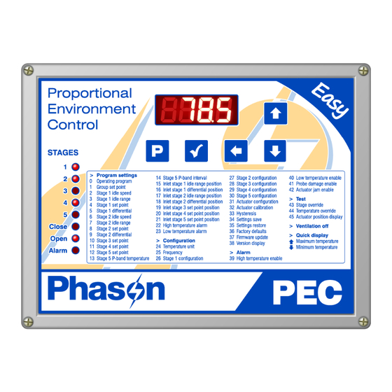
Page 12: Proportional Environment Control Layout
Phason Proportional Environment Control layout Voltage selection switch: set this switch to the correct voltage before installing your PEC. Incoming power terminal: connect the incoming power (120/230 VAC, 50/60 Hz) to this terminal. Temperature probe terminal: connect the temperature probe to this terminal. -
Page 13: Mounting Your Pec
Feedback potentiometers Each actuator you connect must have a feedback potentiometer. The feedback potentiometer, which you connect to the PEC’s feedback terminal, lets the control know how far the actuator’s arm is extended. - Page 14 To connect actuators AC-powered actuators DC-powered actuators The ratings of the actuator must not exceed the ratings of the PEC. 4.4 A at 120 VAC, 2.2 A at 230 VAC, 5 A at 30 VDC PEC inlet relay ratings A system operates more precisely when using the largest amount of stroke that ...
-
Page 15: Connecting Single-Stage Heating Or Cooling Elements
Heating or cooling elements include equipment such as electric heaters, furnaces, and single-speed fans. To connect single-stage heating or cooling elements Connect single-speed heating or cooling elements to your PEC as shown in the following diagrams. Gas-fired furnace or brooder All other single-speed elements The ratings of the equipment must not exceed the ratings of your PEC's relays. -
Page 16: Connecting Variable-Stage Cooling Elements
Variable stage fuses: Using three-phase power If you are connecting your PEC to a three-phase system, connect the control power and the variable cooling equipment to the same phase. Your PEC must be powered from the same phases that supply the equipment. If your PEC power... -
Page 17: Connecting An Alarm System
Incorrect three-phase wiring Connecting an alarm system You can connect an alarm system to your PEC's alarm terminal. An alarm system can be a siren, alarm panel, or auto-dialer. Read your system’s installation guide for installation instructions and information about the type of system: normally open or normally closed. Below are the descriptions for the alarm terminal. -
Page 18: Connecting Temperature Probes
Join all the COM connections together and all the N/O connections together. Your PEC alarm relays must be in parallel with each other so any PEC can trigger the alarm system when an alarm condition occurs. If you are connecting the alarm system to a network of controls and your system uses a ... - Page 19 When crossing other cables or power lines, cross them at a 90-degree angle. To use four-zone averaging The PEC can monitor the temperature in four different zones using four-zone averaging. The control takes an average of the temperatures measured by the four probes and then operates according to the average temperature.
-
Page 20: Connecting The Power Source
Appendix E connected to your PEC. It is very important that the connections and the worksheets are the same, because the next step after closing the cover is to tell your PEC which equipment is connected to each terminal. 1. Make sure all wires are properly connected to the correct terminals. - Page 21 Finishing the installation 5. Switch on the power to your PEC. When you switch on the power to your PEC, the display should show - - -- , followed by the temperature. If the PEC display does not come on, go back to step 1.
-
Page 22: Chapter 3: Configuring Your Pec
What you need to know before configuring your PEC Configuring your PEC means telling it what equipment it will be controlling and how it will be controlling that equipment. For example, your PEC has three relay stages. You need to tell the stages if they will be controlling heating or cooling elements. -
Page 23: Configuring The Main Control Functions
Frequency Hysteresis Selecting the temperature units, parameter 24 Your PEC can display temperatures in either degrees Fahrenheit (°F) or degrees Celsius (°C), but not both at the same time. Default: Fahrenheit To select the temperature unit 1. Press... -
Page 24: Configuring Hysteresis, Parameter 33
4. To return to the Main menu, press once. To return to the Back Main display, press twice. Back Configuring the stages Your PEC has three types of stages: two variable stages, three relay (ON/OFF) stages, and one inlet actuator (OPEN and CLOSE) stage. -
Page 25: Configuring Variable Stages, Parameters 26 And 27
PEC user manual Configuring the stages Configuring variable stages, parameters 26 and 27 Variable stages 1 and 2 control elements that operate with gradually changing voltage, such as variable speed fans. There are three configuration options. ( 0 f f ) – the variable stage is always off. -
Page 26: Configuring Relay Stages, Parameters 28 To 30
Chapter 3: Configuring your PEC Phason Configuring relay stages, parameters 28 to 30 The PEC has three relay stages you can configure as one of the following options. : the relay is always open (OFF). : the relay is always closed (ON). You can use this configuration as an override. -
Page 27: Configuring The Inlet Actuator, Parameter 31
PEC know the position of the actuator when it is fully extended and fully retracted. The PEC uses the limits to define the range of motion it uses when positioning the inlets. The limits tell the control how much to adjust when you want the actuators, for example, only 20% extended. -
Page 28: Testing The Configuration
As you operate each piece of equipment, visually check to see if that equipment is doing what you tell it. For example, when you switch on stage 3 at the PEC, does the equipment you think is connected to that relay switch on? For more information about stage override mode, read on page 46. -
Page 29: Chapter 4: Programming The Pec
What you need to know before programming your PEC Programming the PEC basically means telling the control what you want it to do with the equipment and when you want it done. For example, for a single-speed fan set for cooling, you might say "Switch on when the temperature reaches 80°F."... - Page 30 Chapter 4: Programming the PEC Phason is the speed at which the Stage 2 idle speed Parameter Program A setting stage 2 fan operates when the temperature is at the Group set point (°F) 85.0 (parameter 7). Stage 2 idle range Stage 1 idle speed (%) Stage 1 idle range (°F)
- Page 31 PEC user manual What you need to know before programming your PEC...
-
Page 32: Programming The Parameters
Inlet stage 3 set point position Stage 3 set point If a stage is configured as heat, the PEC does not use the inlet position setting for that stage. is the position the inlet is at when the temperature reaches the... -
Page 33: Programming The Group Set Point, Parameter 1
Programming variable stages, parameters 2 to 9 There are four settings to program for each variable stage. The following diagram explains how the settings work together. For a more-detailed description of how all settings work together, read on page 29. Understanding how the PEC operates... - Page 34 Chapter 4: Programming the PEC Phason When the temperature is below the , the fan is off. Idle range When the temperature reaches the , the fan runs at the The fan continues Idle range Idle speed. to run at the...
-
Page 35: Programming Relay Stages, Parameters 10 To 14
For a detailed description of how normal settings work together with all others, read Understanding on page 29. how the PEC operates How proportional control works (stage 5 only) Proportional heating When configured for proportional heating, the relay controls a pump or valve and operates as a proportional cycle timer. - Page 36 Chapter 4: Programming the PEC Phason The following example uses the default settings for Program A Parameter 12, = 84.0°F Stage 5 set point Parameter 13, = 2.0°F Stage 5 P-band temperature Parameter 14, = 10 minutes Stage 5 P-band interval ...
- Page 37 PEC user manual Programming the parameters The following example uses the default settings for Program A Parameter 12, = 84.0°F Stage 5 set point Parameter 13, = 2.0°F Stage 5 P-band temperature Parameter 14, = 10 minutes Stage 5 P-band interval ...
- Page 38 Chapter 4: Programming the PEC Phason 1. Press until the program you want to adjust displays, for Program example A p r for program A. A pr 2. Press Select The display shows Π0 , the first item in the Program settings menu.
-
Page 39: Programming Inlet Actuator, Parameters 15 To 21
Inlet stage 5 set point position , (parameter 12). Stage 5 set point The PEC does not use the inlet position setting for HEAT or PROPORTIONAL stages. For a more-detailed description of how all settings work together, read ... -
Page 40: Programming Alarm Settings, Parameters 22 And 23
The exceptions to the one-minute minimum are the alarms. The actuator actuator jam power fail jam alarm activates 20 seconds after the PEC detects it and the power fail alarm automatically triggers the relay on a loss of power. - Page 41 20 seconds. With the actuator jam alarm not enabled, if the potentiometer feedback wires are damaged, the PEC cannot read the feedback and tries to position the actuator completely open or completely closed. When an alarm occurs, the...
- Page 42 20 seconds. With the actuator jam alarm not enabled, if the potentiometer feedback wires are damaged, the PEC cannot read the feedback and tries to position the actuator completely open or completely closed. 1. Press...
-
Page 43: Chapter 5: Monitoring And Maintaining Your Pec
Chapter 5: Monitoring and maintaining your PEC Chapter 5 explains how to monitor the PEC after you have installed, configured, and programmed it. Topics in chapter 5 include: below Monitoring your PEC on page 46 Testing settings and equipment ... -
Page 44: Selecting The Operating Program
Phason Selecting the operating program The PEC has seven configurable programs, A, B, C, D, E, F, and G. If you are running a livestock or poultry operation, you might use different programs for different stages of development. Another option is to use different programs for different seasons. - Page 45 Press Select If there was only one alarm message, the PEC clears the message and returns to the main display. If there are additional alarm messages, the PEC displays the next message. Acknowledging alarms clears the alarm message; it does not deactivate the ...
-
Page 46: Testing Settings And Equipment
0 to 100% for variable stages, OFF or ON for relay stages and the alarm relay. For the inlet, there are two options: open and close. When you select open, the PEC displays the position and then opens the inlet until you press . -
Page 47: Using Temperature Override Mode
PEC displays the position and then opens the inlet until you press . When Select you select c L o s , the PEC displays the position and then closes the inlet until you press Select 5. Repeat steps 3 to 4 for each stage you want to test. -
Page 48: Using The Actuator Position Display
Chapter 5: Monitoring and maintaining your PEC Phason Using the actuator position display The actuator position display shows the position of the actuator according to the feedback received from the potentiometer. If the test actuator has not been calibrated, the display shows U ( A L . -
Page 49: Enabling And Disabling Actuator Deicing
PEC user manual Servicing and maintaining your PEC When ventilation is disabled Variable stages are off Cooling stages (relay) are off Actuators close Heating stages function normally The display alternates between the current temperature and U o f f ... -
Page 50: Restoring The Factory Defaults
Restore the factory defaults only as a last resort. It erases ALL your configuration and settings and you will have to reconfigure the control. If you restore your PEC to its factory defaults, disconnect the power to all loads and then reconfigure the control before restoring power to the loads. - Page 51 To save your settings (0Nf 1. Loosen the four screws in the PEC enclosure and then gently remove the cover. Make sure not to disconnect the ribbon cable. 2. Insert the PEC Saver into the connector marked SAVER on the inside top-left of the cover.
-
Page 52: Displaying The Firmware Version
If you need to contact Phason Customer Support about your PEC, you might need to provide them with the firmware version of your control. For more information about technical support, read the back cover of the manual. The PEC displays the firmware version as a number in the format #.##. To display the firmware version (0Nf 1. - Page 53 8. Replace the cover and then tighten the four screws. To update the firmware using the “power off” method 1. Loosen the four screws in the PEC enclosure and then gently remove the cover. Make sure not to disconnect the ribbon cable.
-
Page 54: Replacement Kits And Optional Accessories
PEC. Parts and kits Display kit, model K310063 Should the display of your PEC control fail, you can replace it with a kit. After replacing the display, you will need to reconfigure and program control. Control kits, model KPEC-B Should the bottom circuit board of your PEC control fail, you can replace it with a kit. - Page 55 PEC user manual Servicing and maintaining your PEC Power contactors Phason’s 240-volt power contactors are heavy-duty relays that increase the load handling capability of control relays. Power contactors are ideal for secondary ventilation fans and electric heaters. (PC-240): includes power contactor relay Power contactor relay ...
-
Page 56: Appendixes
After the actuator moves the 5%, it moves back to its proper position. control elements Devices connected to your PEC, such as fans, heaters, actuators, and so on. differential The temperature setting above which a variable stage's fan runs at full speed. - Page 57 The minimum amount of time an alarm condition must be present before the duration PEC signals an alarm. The minimum duration (one minute) prevents alarms from activating when the temperature rises or drops for just a few seconds. For more information, read Programming alarm settings, parameters 22 and on page 40.
-
Page 58: Appendix B: Troubleshooting
59 and then follow the instructions for resolving the alarm condition. messages If you are having a problem using your PEC, see if the problem is described in the table on page 60 and then follow the directions for correcting the problem. -
Page 59: Alarm And Error Messages
Recalibrate the actuator. For more information, read Calibrating an actuator, parameter 32 on page 27. The PEC Saver is not in place Make sure the PEC Saver is inserted correctly and Err1 when trying to save or restore then try again. -
Page 60: Troubleshooting
Troubleshooting The following table lists some problems, possible causes, and possible solutions. If you are having a problem using your PEC, see if the problem is described in the Troubleshooting table and then follow the directions for correcting the problem. - Page 61 PEC user manual Appendix B: Troubleshooting Problem Possible cause Possible solution Variable fan not running Incorrect wiring Correct the wiring. For more information, read Connecting variable-stage cooling elements on page 16. The fuse is open or blown. Check why the fuse was blown and repair ...
-
Page 62: Determining Correct Actuator Feedback Wiring
Appendixes Phason Problem Possible cause Possible solution Actuator moves to an incorrect Actuator needs calibrating Calibrate the actuator. For more position or moves in the opposite information, read Calibrating an actuator, direction. parameter 32 on page 27. Actuator moves using manual override, but not during normal operation. -
Page 63: Appendix C: Factory Defaults
When your PEC leaves the factory, it comes with default settings and configuration. Configuring and programming your PEC changes the factory defaults. Resetting your PEC erases all the configuration and settings you programmed and then restores the defaults. For more information, read on page 50. - Page 64 Appendixes Phason The following table shows all the factory defaults and ranges. Parameter Default Range/options E, F, G 1 Group set point (°F/°C) 85.0 80.0 75.0 70.0 65.0 -13 to 125°F (-25 to 51.7°C) 2 Stage 1 idle speed (%) 0 to 100 % 3 Stage 1 idle range (°F/°C)
-
Page 65: Appendix D: Installation Worksheet
Use the following worksheet to list all the equipment (fans, heaters, and so on that you want your PEC to control. We recommend you make a copy of the worksheet before filling it in incase you need more than one sheet or you make a mistake. -
Page 66: Appendix E: Configuration Worksheets
Appendixes Phason Appendix E: Configuration worksheets Use the on page 65 when completing the configuration Installation Worksheet worksheets. Main control function worksheet For each item, circle or write in the configuration. Item Description Configuration Units The unit of measure for temperature. -
Page 67: Relay Configuration Worksheet
Gas furnace Appendix F: Settings worksheets Appendix F contains worksheets for you to use when programming your PEC settings. Each worksheet contains a brief explanation of the information required. For more information about programming your PEC, see on page 29. -
Page 68: Actuator Settings Worksheet
Appendixes Phason If you need to connect more cooling elements than you have relays available, and you are not using both variable stages, you can use an available variable stage as an ON/OFF stage (for 120/230 VAC-powered equipment only). -
Page 69: Alarm Settings Worksheet
The exceptions to the one-minute minimum are the actuator jam and power fail alarms. The actuator jam alarm activates five seconds after the PEC detects it and the power fail alarm automatically triggers the relay on a loss of power. - Page 70 Appendixes Phason Use manual override or test mode to test and evaluate the operation and performance of your fan motors. For more information, read Testing settings and on page 46. equipment If your fan motors are not running at approximately the correct RPM for the control settings, ...
-
Page 71: Index
Index disabling actuator deicing .......... 49 acknowledging alarms ......44–45 ventilation ..........48–49 active program ..........44 disabling alarms ..........42 actuator deicing ..........49 display cable ........... 12 actuator feedback ........12, 27 displaying minimum/maximum temperatures . 43 actuator jam alarm ......40–41, 45 actuator position display ........ - Page 72 ..........23–24 operating frequency ......... 23–24 temperature units ........23 operating program .......... 44 settings saver ......See PEC Saver stage override mode ......... 46–47 stages ........See relay or variable parameters ..29–32, See also programming or configuration status LEDs ............
- Page 73 Limited warranty This warranty applies only to the Phason Proportional Environment Control (PEC). If you need warranty service, return the product and original proof of purchase to your dealer. Phason Inc. (Phason) warrants the PEC subject to the following terms and conditions.
- Page 74 59 and then Alarm and error messages follow the instructions for resolving the alarm condition. If you are having a problem using your PEC, look in the table on page 60 and then follow the directions Troubleshooting for correcting the problem.
Need help?
Do you have a question about the PEC and is the answer not in the manual?
Questions and answers