
Related Manuals for Schaerer 7300

Summary of Contents for Schaerer 7300
- Page 1 7300 Schaerer Mayfield USA, Inc. Go To Table Of Contents Modular Surgery Table Service and Parts Manual CA802000 FOR USE BY SMI TRAINED TECHNICIANS ONLY SF-1586 Part No. 504-0023-00 Rev. E (5/04)
- Page 2 Go To Table Of Contents...
-
Page 3: Table Of Contents
1.1 Scope of Manual ......... 1-1 Removal / Installation ......4-21 1.2 How to Use Manual ........1-1 4.17 Seat Cylinder Orifice(s) 1.3 Description of 7300 Modular Surgery Removal / Installation ......4-26 Table ............1-1 4.18 Seat Cylinder Pilot Operated Check Valve 1.4 Specifications .......... - Page 4 Bridge Components ........6-8 Position Device ........6-50 (*) Indicates that there has been a serial number break for the illustration and that there are additional point page(s) following the original page. Page ii Printed in U.S.A. © Schaerer Mayfield USA, Inc. 2004...
- Page 5 71130 I.A. Board (36-inch) ......6-89 (*) Indicates that there has been a serial number break for the illustration and that there are additional point page(s) following the original page. Page iii © Schaerer Mayfield USA, Inc. 2004 Printed in U.S.A.
-
Page 6: Important Instructions
Safety First: The primary concern of Refer to the SMI “Limited Warranty” printed on the Schaerer Mayfield USA is that this surgery table is back cover of the Installation and Operation Manual for maintained with the safety of the patient and staff in warranty information. -
Page 7: Section I General Information
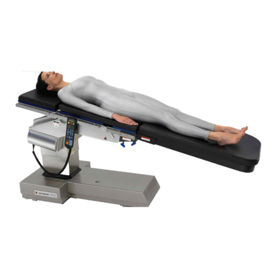
2). intended to be used by SMI’s authorized service technicians. The 7300 Modular Surgery Table is designed for use as a general surgery table on which virtually any surgical 1.2 How to Use Manual procedure can be accomplished. 7300 was designed for maximum C-arm access and X-ray visibility. - Page 8 Return To Table Of Contents SECTION I GENERAL INFORMATION Figure 1-1. Major Components (Sheet 1 of 2) Page 1-2 © Schaerer Mayfield USA, Inc. 2004 Printed in U.S.A.
- Page 9 Return To Table Of Contents SECTION I GENERAL INFORMATION Figure 1-1. Major Components (Sheet 2 of 2) Page 1-3 © Schaerer Mayfield USA, Inc. 2004 Printed in U.S.A.
- Page 10 After eight seconds, main controller de-energizes main floor lock valve spool Page 1-4 © Schaerer Mayfield USA, Inc. 2004 Printed in U.S.A.
- Page 11 Oil also flows thru a pilot line (represented by a dashed line on hydraulic schematic) and extends a pilot piston. Page 1-5 © Schaerer Mayfield USA, Inc. 2004 Printed in U.S.A.
- Page 12 (oil will now flow in new oil flow path that has flows thru a check valve (A) and into base of column been created; this path is shown by crossed flow Page 1-6 © Schaerer Mayfield USA, Inc. 2004 Printed in U.S.A.
-
Page 13: 1.4 Specifications
Oil flows thru three pilot lines (represented by dashed lines on hydraulic schematic) and extends three pilot pistons, which Factual data for the 7300 Modular Surgery Table is forces open three check valves; check valves A, B, and provided in Table 1-1. -
Page 14: 1.5 Parts Replacement Ordering
(1) Refer to Figure 1-2 to determine the location of the model number and serial number of the unit Figure 1-2. Model Number / Serial and record this data. Number Location Page 1-8 © Schaerer Mayfield USA, Inc. 2004 Printed in U.S.A. -
Page 15: 1.6 Special Tools
7100 or 7300 surgical tables around. Drive Cincinnati, Ohio 45227 (800) 755-6381 Tipping Tool Schaerer Mayfield USA 502-0168-00 Used to tip over Model 7100 or 7300 surgical 4900 Charlemar tables to access base of table for servicing. Drive Cincinnati, Ohio 45227 (800) 755-6381 Page 1-9 ©... - Page 16 Return To Table Of Contents SECTION I GENERAL INFORMATION Page 1-10 © Schaerer Mayfield USA, Inc. 2004 Printed in U.S.A.
-
Page 17: Section Ii Testing And Troubleshooting
(8) Move the surgery table around. (9) Observe. The casters should swivel freely and In order to effectively diagnose malfunctions of the 7300 the table should roll easily on the casters. The Modular Surgical Table, it may be necessary to perform table should not wobble. - Page 18 TILT TRENDEL- UNLOCKED LEFT ENBURG POSITION LATCH HANDLE POSITIONS (TYP. 2 PLACES) REVERSE LATERAL TRENDEL- TILT ENBURG TABLE RIGHT DOWN CA819700 Figure 2-1. Operational Test (Sheet 1 of 2) Page 2-2 © Schaerer Mayfield USA, Inc. 2004 Printed in U.S.A.
- Page 19 Seat Up to Seat Down ....18.5 to 21.5 seconds Trendelenburg ........0° to 28° (±1°) Reverse Trendelenburg ......0° to -28° (±1°) Lateral Tilt ....0° to -18° (±1°) in either direction Page 2-3 © Schaerer Mayfield USA, Inc. 2004 Printed in U.S.A.
- Page 20 (31) Remove weight from table top. (32) Press and hold the SYSTEM OVERRIDE button while pressing the function buttons, one at a time, on the emergency override panel. Page 2-4 Printed in U.S.A. © Schaerer Mayfield USA, Inc. 2004...
- Page 21 TERMINAL (BACK) END. BROWN GREY WHITE GREEN BLUE GREEN BROWN BROWN GREEN St23 HAND YELLOW WHITE CONTROL BLUE PORT YELLOW WHITE St33 St35 GREY St32 BROWN CA819900 Figure 2-2. Voltage Checks Page 2-5 Printed in U.S.A. © Schaerer Mayfield USA, Inc. 2004...
-
Page 22: 2.2 Troubleshooting Procedures
10 amp fuse on main Perform continuity check Replace 10 amp fuse. See illuminates, but table is controller board is blown. on 10 amp fuse. Figure 5-1 for fuse location. powerless. Page 2-6 Printed in U.S.A. © Schaerer Mayfield USA, Inc. 2004... - Page 23 Test and 4.41. charging / power driver Points S and T for motor board to blow. # 1 or Test Points U and V for motor # 2. Page 2-7 Printed in U.S.A. © Schaerer Mayfield USA, Inc. 2004...
- Page 24 (when foot depressed). switch is pressed, there should be continuity between its two terminals). Page 2-8 Printed in U.S.A. © Schaerer Mayfield USA, Inc. 2004...
- Page 25 If malfunctioning, replace main is malfunctioning - stuck check. Perform floor lock status switch. Refer open. continuity check on to para 4.42. normally closed status switch (switch untripped = continuity). Page 2-9 Printed in U.S.A. © Schaerer Mayfield USA, Inc. 2004...
- Page 26 4.26. motor. (If only COLUMN UP function causes error code E04, motor #2 could be malfunctioning - motor #2 only runs for this function during normal operation). Page 2-10 © Schaerer Mayfield USA, Inc. 2004 Printed in U.S.A.
- Page 27 Main controller board is Replace suspect main Replace main controller malfunctioning. controller board with board. Refer to para 4.31. known working main controller board. Page 2-11 © Schaerer Mayfield USA, Inc. 2004 Printed in U.S.A.
- Page 28 (E13), replace motor #1 overheats primary thermostat. Refer to continually. para 4.40. If motor #1 still continues to overheat (E13), replace motor. Refer to para 4.26. Page 2-12 © Schaerer Mayfield USA, Inc. 2004 Printed in U.S.A.
- Page 29 Clean out check valve or check valve is matter in pilot operated any foreign matter. Replace clogged. check valve. any broken or bent components. Page 2-13 © Schaerer Mayfield USA, Inc. 2004 Printed in U.S.A.
- Page 30 Check for missing orifice. Replace orifice. the rest are operating displayed, but function is function is missing ( NOTE: properly. too fast. only applies to early units which have orifices external to cylinders.) Page 2-14 © Schaerer Mayfield USA, Inc. 2004 Printed in U.S.A.
- Page 31 Refer to para 4.45. Latch handle is binding. Check for foreign matter Remove latch handle and build-up. clean. Refer to para 4.45. Page 2-15 © Schaerer Mayfield USA, Inc. 2004 Printed in U.S.A.
- Page 32 "Level" button is screws with removable pressed. threadlocking adhesive (Loctite 242). Refer to para 4.19. Page 2-16 © Schaerer Mayfield USA, Inc. 2004 Printed in U.S.A.
-
Page 33: Section Iii Scheduled Maintenance
(Refer to para 2.1). Replace or adjust any malfunctioning components. Every Six Years Reservoir strainers Replace reservoir strainer for each pump unit. Refer to para 4.27. Discharge Filter Replace discharge filter. Refer to para 4.24. Page 3-1 © Schaerer Mayfield USA, Inc. 2004 Printed in U.S.A. - Page 34 Return To Table Of Contents SECTION III SCHEDULED MAINTENANCE Page 3-2 © Schaerer Mayfield USA, Inc. 2004 Printed in U.S.A.
-
Page 35: 4.1 Introduction
(6) Using a flashlight, check oil level. Oil should be approximately 1 in. (2.54 cm) below top of oil check hole opening, which is when oil just starts to cover top of motor pump housing. Page 4-1 © Schaerer Mayfield USA, Inc. 2004 Printed in U.S.A. -
Page 36: Calibration Of Return To Level / Neutral Position
(+ / - 1°) (+ / - 1°) IO N S IT IO N LEVEL UNLOCK IG H IG H T IL T IL 7300 CA805800 Figure 4-2. Leveling Table Top Page 4-2 © Schaerer Mayfield USA, Inc. 2004 Printed in U.S.A. - Page 37 (13) Install lower case (3) on upper case (2) and secure with six screws (1). (14) If removed, install cushion on back section. (15) If removed, install head section on back section. See Figure 4-2. Page 4-3 © Schaerer Mayfield USA, Inc. 2004 Printed in U.S.A.
-
Page 38: Hand Control Button Board Removal / Installation
(4) Remove four screws (4) and standoffs (5) from hand control board (2). B. Installation (1) Install four standoffs (5) on hand control board (2) and secure with four screws (4). Page 4-4 © Schaerer Mayfield USA, Inc. 2004 Printed in U.S.A. -
Page 39: Seat Cylinders Synchronization Procedure
Release button and repress it to continue moving to full up or down position. (10) Using hand control, press SEAT UP button to raise R.H. seat weldment (1) upward as far as it will go. Page 4-5 © Schaerer Mayfield USA, Inc. 2004 Printed in U.S.A. - Page 40 DOWN functions a little at a time; it doesn't take check synchronization of seat cylinders (R.H. much movement. seat weldment (1) should be even with L.H. seat weldment (2). Page 4-6 Printed in U.S.A. © Schaerer Mayfield USA, Inc. 2004...
-
Page 41: Column Cylinder Slave Line Volume Adjustment
Then, when column assembly is lowered, the over-compressed oil in slave line causes column cylinder to "jump" downward, making a noticeable noise and a notice- able jolting movement. Page 4-7 © Schaerer Mayfield USA, Inc. 2004 Printed in U.S.A. - Page 42 IG H IG H T IL T IL TABLE TABLE DOWN F L E F L E 7 3 0 CA806300 Figure 4-7. Column Cylinder Slave Line Volume Adjustment Page 4-8 © Schaerer Mayfield USA, Inc. 2004 Printed in U.S.A.
-
Page 43: Trendelenburg Cylinder Removal / Installation
(6). (4) Remove four screws (5) which secure column covers (6) and upper column cover (7) to column assembly (8). Support CA806400 Figure 4-8. Covers Removal / Installation Page 4-9 © Schaerer Mayfield USA, Inc. 2004 Printed in U.S.A. - Page 44 (13) Using a hammer and punch, drive cylinder connecting pin (12) out of pivot bracket (9), and (15) Add oil to reservoir (Refer to para 4.2). separate pivot bracket from Trendelenburg cylinder (4). Page 4-10 Printed in U.S.A. © Schaerer Mayfield USA, Inc. 2004...
-
Page 45: Trendelenburg Pilot Operated Check Valve Removal / Installation
(6). Also, illustration shows removal / installation of both pilot operated check valves. Follow portion of art that applies. Support CA806401 Figure 4-10. Covers Removal / Installation Page 4-11 © Schaerer Mayfield USA, Inc. 2004 Printed in U.S.A. - Page 46 Check Valve Removal / Installation affects input to base of Trendelenburg cylinder, coat o-ring of small plug (A) with oil; then install small plug in manifold (2). Then, go to step 9. Page 4-12 Printed in U.S.A. © Schaerer Mayfield USA, Inc. 2004...
-
Page 47: Trendelenburg Cylinder Orifice(S) Removal / Installation
(13) Secure column covers (4) together with six ROD END screws (7). ORIFICE (14) Connect spring (1) to front bridge cover (2). CATCH CA765101 Figure 4-12 Trendelenburg Cylinder Orifice(s) Removal / Installation Page 4-13 Printed in U.S.A. © Schaerer Mayfield USA, Inc. 2004... -
Page 48: Trendelenburg Position Sensor Removal / Installation
(2), and spacer (4) from R.H. tilt EDGE OF WHEEL WHICH IS CENTER POINT bracket (5). FACES TOWARD TERMINALS CA7630 Figure 4-13. Trendelenburg Position Sensor Removal / Installation Page 4-14 © Schaerer Mayfield USA, Inc. 2004 Printed in U.S.A. -
Page 49: Lateral Tilt Cylinder Removal / Installation
(6) Tag and disconnect hose (2) from male connec- tor (3). POST CA7632 Figure 4-15. Lateral Tilt Cylinder Removal / Installation CA807500 Figure 4-14. Covers Removal / Installation Page 4-15 © Schaerer Mayfield USA, Inc. 2004 Printed in U.S.A. -
Page 50: Lateral Tilt Orifice(S) Removal / Installation
(2). (11) Install four plugs (1) on back section table top (3). (12) Add oil to reservoir (Refer to para 4.2). CA807000 Figure 4-16. Covers Removal / Installation Page 4-16 © Schaerer Mayfield USA, Inc. 2004 Printed in U.S.A. - Page 51 L.H. side weldments (4) and secure with four screws (2). (6) Install four plugs (1) on back section table top (3). CA7634 Figure 4-17. Lateral Tilt Orifices Removal / Installation Page 4-17 © Schaerer Mayfield USA, Inc. 2004 Printed in U.S.A.
-
Page 52: Lateral Tilt Pilot Operated Check Valve Removal / Installation
(6), nylon washer (7), and check valve (8) from using excessive force on guide shaft will damage manifold (3). components. (9) Using a small punch or Allen wrench, push pilot piston (9) out of manifold (3). Page 4-18 © Schaerer Mayfield USA, Inc. 2004 Printed in U.S.A. - Page 53 (5) Install spring (10) and pilot piston (9) in mani- fold (3). (6) Using a punch or Allen wrench, push on pilot piston (9) to ensure that it moves freely (ap- proximately 1/8 in. (3.2 mm) travel). Page 4-19 © Schaerer Mayfield USA, Inc. 2004 Printed in U.S.A.
-
Page 54: Lateral Tilt Position Sensor Removal / Installation
EDGE OF WHEEL WHICH IS CENTER POINT FACES TOWARD TERMINALS ( +/- 3°) CA807400 CA807200 Figure 4-21. Lateral Position Figure 4-20. Covers Removal / Installation Sensor Removal / Installation Page 4-20 © Schaerer Mayfield USA, Inc. 2004 Printed in U.S.A. -
Page 55: Seat Cylinder Removal / Installation
L.H. side weldments (4) and secure with four screws (2). (9) Install four plugs (1) on back section table top (3). POST CA807500 Figure 4-22. Covers Removal / Installation Page 4-21 © Schaerer Mayfield USA, Inc. 2004 Printed in U.S.A. - Page 56 (11) Raise seat spar weldment (5) up by hand and insert a screwdriver thru pin hole to hold in Figure 4-23. Seat Cylinder position. Disconnection / Connection Page 4-22 © Schaerer Mayfield USA, Inc. 2004 Printed in U.S.A.
- Page 57 Remove two fitting connectors (B), fitting valve assembly (2) into side weldment (3) and seals (C), and hoses (A) from L.H. seat secure with two screws (1). cylinder (D). Page 4-23 Printed in U.S.A. © Schaerer Mayfield USA, Inc. 2004...
- Page 58 (8) Remove screwdriver and lower seat spar weldment (5) down. (6) Align base of seat cylinder (8, Figure 4-24) with side weldment (2) and secure with pivot pin (7). Page 4-24 © Schaerer Mayfield USA, Inc. 2004 Printed in U.S.A.
- Page 59 (6). (16) Add oil to reservoir (Refer to para 4.2). (17) Perform seat cylinder synchronization procedure (Refer to para 4.6). Figure 4-26. Seat Cylinder Removal / Installation Page 4-25 Printed in U.S.A. © Schaerer Mayfield USA, Inc. 2004...
-
Page 60: Seat Cylinder Orifice(S) Removal / Installation
(6) Install seat cylinder (Perform steps 3 thru 19 of para 4.16B). (7) Add oil to reservoir (Refer to para 4.2). (8) Perform seat cylinder synchronization procedure (Refer to para 4.6). Page 4-26 © Schaerer Mayfield USA, Inc. 2004 Printed in U.S.A. -
Page 61: Seat Cylinder Pilot Operated Check Valve Removal / Installation
(2); then unscrew guide shaft two full turns. CA7662 (5) Install spring (14) and pilot piston (13) in lower Figure 4-28. Seat Cylinder Pilot Operated manifold (2). Check Valve Removal / Installation Page 4-27 © Schaerer Mayfield USA, Inc. 2004 Printed in U.S.A. -
Page 62: Seat Position Sensor Removal / Installation
4.16). (10) Add oil to reservoir (Refer to para 4.2). (11) Perform seat cylinders synchronization proce- dure (Refer to para 4.6). CA807000 Figure 4-29. Covers Removal / Installation Page 4-28 © Schaerer Mayfield USA, Inc. 2004 Printed in U.S.A. - Page 63 Removal / Installation shrunk securely in place. (10) Coat threads of drive shaft (5) with removable threadlocking adhesive (Loctite 242). (11) Install drive shaft (5) on pivot shaft (10). Page 4-29 © Schaerer Mayfield USA, Inc. 2004 Printed in U.S.A.
- Page 64 (2). CA805600 (28) Install four plugs (1) on back section table Figure 4-31 top (3). (29) Perform calibration of return to level / neutral position (Refer to para 4.3). Page 4-30 © Schaerer Mayfield USA, Inc. 2004 Printed in U.S.A.
-
Page 65: Column Cylinder Removal / Installation
(8) Cut cable ties securing hoses together. CA807000 NOTE Figure 4-32. Covers Removal / Installation Propping table top up slightly will prevent oil from running out of top of column cylinder. Page 4-31 © Schaerer Mayfield USA, Inc. 2004 Printed in U.S.A. - Page 66 (21) Remove column cylinder (5) from column (2) Coat mating surfaces of bearing (7) and base of weldment (4). column cylinder (5) with Lithium White grease. Page 4-32 © Schaerer Mayfield USA, Inc. 2004 Printed in U.S.A.
- Page 67 (M07235) to install locking nut base weldment (6) and secure in this position (13) in column assembly (12). Refer to Table with four screws (7). 1-2 for special tool. Page 4-33 Printed in U.S.A. © Schaerer Mayfield USA, Inc. 2004...
-
Page 68: Column Pilot Operated Check Valve Removal / Installation
(32) Add oil to reservoir (Refer to para 4.2). (33) Perform column cylinder slave line volume adjustment procedure (Refer to para 4.6). CA7669 Figure 4-36. Column Pilot Operated Check Valve Removal / Installation Page 4-34 Printed in U.S.A. © Schaerer Mayfield USA, Inc. 2004... -
Page 69: Typical L.h. And R.h. Control Valve Solenoids Removal / Installation
(6) Make sure speednuts (14) are aligned with screw holes, then carefully push R.H. or L.H. control valve assembly (2) up into side weldment (3) and secure with two screws (1). Page 4-35 © Schaerer Mayfield USA, Inc. 2004 Printed in U.S.A. - Page 70 Return To Table Of Contents Figure 4-37. Control Valve Solenoids Removal / Installation Page 4-36 © Schaerer Mayfield USA, Inc. 2004 Printed in U.S.A.
-
Page 71: Typical Base Mounted Control Valve Solenoids Removal / Installation
(1) Lay table onto its left side. ALL FLOOR LOCK (UNLOCK) COLUMN DOWN MAIN FLOOR COLUMN UP OUTRIGGER FLOOR LOCK (LOCK) CA817000 HA5486-00 Figure 4-38. Control Valve Solenoids Removal / Installation Page 4-37 © Schaerer Mayfield USA, Inc. 2004 Printed in U.S.A. - Page 72 (6), two screws (5), and two screws (4). (7) Install main cover (2) on base weldment (3) and secure with six screws (1). (8) Raise table to an upright position. Page 4-38 Printed in U.S.A. © Schaerer Mayfield USA, Inc. 2004...
-
Page 73: Discharge Filter Replacement
(6) Work tube assembly (15) around and pull tube cover (2) from base weldment (3). and discharge filter (17) out base weldment (3). CA817100 Figure 4-39. Discharge Filter Removal / Installation Page 4-39 © Schaerer Mayfield USA, Inc. 2004 Printed in U.S.A. - Page 74 (6) Coat o-rings on fitting seal (14) and fitting connector (13) with oil. (7) Connect tube assembly (15) to motor pump (16) and secure with fitting seal (14) and fitting connector (13). Page 4-40 © Schaerer Mayfield USA, Inc. 2004 Printed in U.S.A.
-
Page 75: Main Floor Lock Or Outrigger Floor Lock Cylinder Removal / Installation
(7) and secure with setscrew (5). (5) Secure setscrew (5) in place with jam nut (4). (6) Install caster (2) on caster fork (3) and secure by tightening two locknuts (1). Page 4-41 © Schaerer Mayfield USA, Inc. 2004 Printed in U.S.A. -
Page 76: Motor Or Motor Pump Removal / Installation
(4) until it is out of (8) Remove two screws (1, Figure 4-44), two way. screws (2), mounting bracket (3), and partially remove control box (4) from base weldment (5). Page 4-42 © Schaerer Mayfield USA, Inc. 2004 Printed in U.S.A. - Page 77 (11), and four wires (9) from two (2) Position secondary thermostat (14) and primary terminal posts of motor (12). thermostat (13) on motor (12) and secure with two cable ties. Page 4-43 © Schaerer Mayfield USA, Inc. 2004 Printed in U.S.A.
- Page 78 (12) Pull tube assembly (5) w/discharge filter back CA817500 into position in base weldment (4). Figure 4-45. Motor Pump Assembly Removal / Installation Figure 4-46. Motor Removal / Installation Page 4-44 © Schaerer Mayfield USA, Inc. 2004 Printed in U.S.A.
-
Page 79: Pump Unit Removal / Installation
(14). (4) Install coupler (11) on end of motor shaft (12). (5) Coat o-rings (9 and 10) with oil. (6) Install o-rings (9 and 10) on pump unit (8). Page 4-45 © Schaerer Mayfield USA, Inc. 2004 Printed in U.S.A. - Page 80 (10) Install pump cover (1) on manifold (5) and secure with four lockwashers (3) and screws (2). (11) Install shipping plug in pump cover (1). (12) Perform steps 11 thru 25 of para 4.26 B, Installation. Page 4-46 Printed in U.S.A. © Schaerer Mayfield USA, Inc. 2004...
-
Page 81: Motor Pump Output Check Valve Removal / Installation
(6) Install main cover (2, Figure 4-48) on base weldment (3) and secure with six screws (1). CA818100 (7) Raise table to its upright position. Figure 4-49. Motor Pump Output Check Valve Removal / Installation Page 4-47 Printed in U.S.A. © Schaerer Mayfield USA, Inc. 2004... -
Page 82: Motor Pump Pressure Relief Valve Removal / Installation
(2). Tighten adjusting screw (2) only 1 to 1-1/2 turns. CA818000 (3) Disconnect tube (1, Figure 4-52) from swivel Figure 4-50. Motor Pump Access fitting (2). Page 4-48 Printed in U.S.A. © Schaerer Mayfield USA, Inc. 2004... - Page 83 SEAT UP or SEAT Screwing adjusting screw inward raises pressure DOWN function while observing pressure gauge setting of pressure relief valve. Unscrewing adjusting reading. screw lowers pressure setting of pressure relief valve. Page 4-49 © Schaerer Mayfield USA, Inc. 2004 Printed in U.S.A.
-
Page 84: Outrigger Pressure Relief Valve Removal / Installation
(22) Install main cover (2, Figure 4-50) on base weldment (3) and secure with six screws (1). (23) Raise table to its upright position. CA818000 Figure 4-53. Access to Base Components Page 4-50 Printed in U.S.A. © Schaerer Mayfield USA, Inc. 2004... - Page 85 (4) Disconnect hose (1, Figure 4-55) from male (16) Open shutoff valve of Test Gauge Assembly to connector (2). allow oil pressure to dissipate; then close shutoff valve. (5) Disconnect hose (3) from swivel fitting (4). Page 4-51 © Schaerer Mayfield USA, Inc. 2004 Printed in U.S.A.
- Page 86 (23) Disconnect hose (3) from TEE of Test Gauge Assembly. (20) Lay table onto its left side. (24) Disconnect TEE from swivel fitting (4). (25) Disconnect hose (B) of Test Gauge Assembly from male connector (2). Page 4-52 Printed in U.S.A. © Schaerer Mayfield USA, Inc. 2004...
-
Page 87: Main Controller Board Removal / Installation
(with leg section installed). (2) Remove five screws (1, Figure 4-56) and battery cover (2) from base weldment (3). CA818600 Figure 4-56. Control Box Removal / Installation Page 4-53 Printed in U.S.A. © Schaerer Mayfield USA, Inc. 2004... - Page 88 (9) Raise table to its upright position. (10) Perform calibration of return to level / neutral position (Refer to para 4.3). HA5485-00 Figure 4-57. Main Controller Board Removal / Installation Page 4-54 © Schaerer Mayfield USA, Inc. 2004 Printed in U.S.A.
-
Page 89: Charging / Power Driver Board Removal / Installation
(10) Tag and disconnect six wires (6) from charging / power driver board (5). (1) Coat threads of two screws (7, Figure 4-59) and two screws (8) with hydraulic sealant (Loctite 569). Page 4-55 © Schaerer Mayfield USA, Inc. 2004 Printed in U.S.A. - Page 90 (2) Install charging / power driver board (5) in electrical box (2) and secure with two lockwashers (9), screws (8), and two screws (7). (3) Connect six wires (6) to charging / power driver board (5). Page 4-56 Printed in U.S.A. © Schaerer Mayfield USA, Inc. 2004...
-
Page 91: Emergency Override Panel Removal / Installation
Assure all switch actuator plates are in place before installing emergency override board. (1) Install emergency override board (7) on switch and secure with eight screws (8). (2) Connect wire harness Page 4-57 © Schaerer Mayfield USA, Inc. 2004 Printed in U.S.A. -
Page 92: Distribution Board Removal / Installation
(1) from standoffs (6). (11) Remove four screws (7) and four cable tie standoff assemblies (8) from distribution CA807000 board (1). Figure 4-61. Covers Removal / Installation Page 4-58 © Schaerer Mayfield USA, Inc. 2004 Printed in U.S.A. -
Page 93: Rfi Filter Removal / Installation
(2) Connect three wire groups (2) and two wires (1) to terminals of RFI filter (3). (3) Install bracket assembly (11, Figure 4-63) on base weldment (3) and secure with two screws (10). Page 4-59 © Schaerer Mayfield USA, Inc. 2004 Printed in U.S.A. - Page 94 (3) and secure with setscrew (8). (5) Secure setscrew (8) in place with jam nut (7). (6) Install caster (5) on caster fork (6) and secure by tightening two locknuts (4). Page 4-60 Printed in U.S.A. © Schaerer Mayfield USA, Inc. 2004...
-
Page 95: Transformer Removal / Installation
(12) Disconnect four wires (11) from "fish wire", making sure "fish wire" remains in base weldment (5) to assist in installation. (13) Cut cable ties securing four wires (11) together. (14) Remove transformer (8). Page 4-61 © Schaerer Mayfield USA, Inc. 2004 Printed in U.S.A. - Page 96 Return To Table Of Contents SECTION IV MAINTENANCE / SERVICE RELEASE TABS SLOT "B" SLOT "A" HA5505-00 Figure 4-65. Transformer Removal / Installation Page 4-62 Printed in U.S.A. © Schaerer Mayfield USA, Inc. 2004...
-
Page 97: Line Power Pilot Lamp Removal / Installation
(3) Perform steps 3 thru 8 of para 4.35B (installing RFI filter). RFI filter). LOCKING HA5507-00 HA5506-00 Figure 4-67. Plug Receptacle Removal / Installation Figure 4-66. Line Power Pilot Lamp Removal / Installation Page 4-63 © Schaerer Mayfield USA, Inc. 2004 Printed in U.S.A. -
Page 98: Batteries Removal / Installation
(6) Raise table to its upright position. nals of four batteries (5). (5) Remove four batteries (5) from base weld- ment (3). HA5508-00 Figure 4-68. Batteries Removal / Installation Page 4-64 © Schaerer Mayfield USA, Inc. 2004 Printed in U.S.A. -
Page 99: Primary Thermostat Removal / Installation
NOTE Use proper solder techniques and 60/40 resin core solder. 3/4" PIECE OF SHRINK WRAP TUBING CABLE TIES TERMINAL POST CA818900 Figure 4-69. Primary Thermal Fuse Removal / Installation Page 4-65 © Schaerer Mayfield USA, Inc. 2004 Printed in U.S.A. -
Page 100: Secondary Thermostat Removal / Installation
Removal / Installation cylinders are in unlocked (retracted) position and will not be tripped when floor lock cylinders are in locked (extended) position. Page 4-66 Printed in U.S.A. © Schaerer Mayfield USA, Inc. 2004... - Page 101 POSITION control should read FLOOR LOCKED. Error code E01 (Floor Lock Status Switch Is Not Responding) should not display. HA551100 Figure 4-71. Floor Lock Status Switch Removal / Installation Page 4-67 © Schaerer Mayfield USA, Inc. 2004 Printed in U.S.A.
-
Page 102: Head Section Gas Spring Removal / Installation / Adjustment
The posts should be synchronized in direction (as viewed from base of gas spring) will same position. cause the post to move later / not as far as it had previously. Page 4-68 © Schaerer Mayfield USA, Inc. 2004 Printed in U.S.A. -
Page 103: Foot Control Interface Board Removal / Installation
(2). (5) Using a clear bonding adhesive (Loctite 414), glue gasket seal (1) to lower cover (3). CA7672 Figure 4-73. Foot Control Interface Board Removal / Installation Page 4-69 © Schaerer Mayfield USA, Inc. 2004 Printed in U.S.A. -
Page 104: Typical Latch Mechanism Removal / Installation
Install spring washers as follows: Two spring wash- ers on post of end cap (14) (concave up); then two Figure 4-74. Covers Removal / Installation more, concave down. Repeat until all spring washers are installed. Page 4-70 © Schaerer Mayfield USA, Inc. 2004 Printed in U.S.A. -
Page 105: Typical Floor Lock Check Valve Removal / Installation
Make sure guide shaft bottoms out. Fail- ure to do so will result in improper func- tioning of check valve. However, do not use exces- sive force on guide shaft to prevent damaging components. Page 4-71 © Schaerer Mayfield USA, Inc. 2004 Printed in U.S.A. - Page 106 (7) Raise table to an upright position. (5) Install manifold assembly (8) in base weldment (3) and secure with two spacers (7), mounting bracket (6), two screws (5), and two screws (4). Page 4-72 © Schaerer Mayfield USA, Inc. 2004 Printed in U.S.A.
-
Page 107: Articulating Leg Transfer Board
(5). (5) Remove the locknut (6) then disconnect the ball joint connector (5) from the handle weldment (7). Figure 4-77. Articulating Leg Board Assembly Handle Adjustment Page 4-73 © Schaerer Mayfield USA, Inc. 2004 Printed in U.S.A. - Page 108 (5) Loosen jam nut (6) on rod of gas cylinder (7). (11) Check operation. (12) Install cover (2) and cushion. Figure 4-78. Articulating Leg Board Assembly Gas Cylinder Adjustment Page 4-74 © Schaerer Mayfield USA, Inc. 2004 Printed in U.S.A.
-
Page 109: Bell Footpiece Traction Crank Assembly
(2) Remove clamping knob (1) and screw (2) that bushing (11), washer (15) and klipring (16) from secure accessories to end of traction barrel (7). traction screw (17). Figure 4-79. Bell Footpiece / Traction Crank Assembly. Page 4-75 © Schaerer Mayfield USA, Inc. 2004 Printed in U.S.A. - Page 110 Drop handle (5) must go through clearance (un- threaded) hole of clamp weldment (6) first and then into threaded hole. (6) Install drop handle (5) onto clamp weldment (6). Page 4-76 © Schaerer Mayfield USA, Inc. 2004 Printed in U.S.A.
-
Page 111: Section V Schematics And Diagrams
/ current flow for the table orientation switches. Figure 5-1, Sheets 1 and 2 illustrate the logic / current See Pages 5-2 and 5-3 for Figure 5-1 (This page intentionally left blank) Page 5-1 Printed in U.S.A. © Schaerer Mayfield USA, Inc. 2004... - Page 112 WHITE WHITE WHITE / GREEN GREY BROWN / YELLOW VIOLET BLUE BLACK YELLOW / WHITE GREY / WHITE BROWN BROWN / GREY PINK BROWN / GREEN YELLOW GREEN CA805501 Page 5-2 Printed in U.S.A. © Schaerer Mayfield USA, Inc. 2004...
- Page 113 VIOLET RED / BLUE GREY / PINK BLUE BLACK GREEN YELLOW BROWN PINK PINK YELLOW BROWN GREEN BLACK GREY / PINK BLUE RED / BLUE VIOLET GREY WHITE CA805502 Page 5-3 Printed in U.S.A. © Schaerer Mayfield USA, Inc. 2004...
-
Page 114: 5.2 Hydraulic Flow Diagram
5.2 Hydraulic Flow Diagram Figure 5-3, Sheets 1 and 2 illustrate the hydraulic flow paths thru the hydraulic components in the table. CA805400 Figure 5-3 (Sheet 1 of 2). Hydraulic Flow Diagram Page 5-4 Printed in U.S.A. © Schaerer Mayfield USA, Inc. 2004... -
Page 115: 5.3 Hand Control Messages
Informs the operator that the self diagnostic function of the table has detected a table malfunction which will require service by a qualified service technician. ERROR CODE Exx Provides information to a qualified service technician as to what type of malfunction exists. Page 5-5 Printed in U.S.A. © Schaerer Mayfield USA, Inc. 2004... -
Page 116: 5.4 Error Code Chart
Wrong hand control is plugged into table. Some units will display the E14 Error Code and some may display "Wait" for a short period and then screen will go blank. E16 or "Wait" Page 5-6 Printed in U.S.A. © Schaerer Mayfield USA, Inc. 2004... -
Page 117: Section Vi Parts List
The Part No. column lists the SMI part number illustrations. Adherence to these requirements is for that component. essential. Page 6.1 Printed in U.S.A. © Schaerer Mayfield USA, Inc. 2004... -
Page 118: Pictorial Index
Column Assembly Components ..6-18 GS085650 Column Assembly ......6-19 Trendelenberg Cylinder Assembly .. 6-20 Column Cylinder Assembly ..... 6-21 Hand Control Assembly ....6-22 Always Specify Model & Serial Number Page 6-2 © Schaerer Mayfield USA, Inc. 2004 Printed in U.S.A. - Page 119 Traction Unit .......... 2 w/ Cushion (55-inch) ...... 6-93 73011 Traction Unit Extension ......2 73005 X-ray Top Set, 7300 ......6-94 73013 Lateral Well Leg Holder ......1 73015 Articulating Bracket ....... 1 Always Specify Model & Serial Number ©...
- Page 120 Caution Label (Shock & Covers) ..4 561-0370-00 Serial Number Label ......1 561-0198-00 U.L. Listing Label ......... 1 561-0240-00 Safety Warning Label (Exclamation) ..6 Always Specify Model & Serial Number Page 6-4 © Schaerer Mayfield USA, Inc. 2004 Printed in U.S.A.
- Page 121 (Refer to "Pelvic Base" Accessory • GS086050-2 • Velcro Loop ......... 1 Elsewhere) ..........1 GS086059 Back Section Table Top (Includes Item 5) ........1 Always Specify Model & Serial Number Page 6-5 © Schaerer Mayfield USA, Inc. 2004 Printed in U.S.A.
- Page 122 • L.H. Column Cover (Segment 3) ..1 GS085036 Reservoir Fill Cover ......1 GS085519-9 • L.H. Column Cover (Segment 4) ..1 Always Specify Model & Serial Number Page 6-6 © Schaerer Mayfield USA, Inc. 2004 Printed in U.S.A.
- Page 123 • Spacer Pad ........2 GS084914 • Rubber Cushion ......... 2 GS084979 • Spacer Pad ........1 GS086408 • Upper Pivot Pins, Front ...... 2 Always Specify Model & Serial Number Page 6-7 © Schaerer Mayfield USA, Inc. 2004 Printed in U.S.A.
- Page 124 Lockwasher .......... 4 GS085556 R.H. Mounting Plate ......1 GS1400101 Shim Washer ........AR GS1218077 Screw ..........13 GS085577 Square Headed Screw (Apply Green Loctite #042-0025-00) ......1 Always Specify Model & Serial Number Page 6-8 © Schaerer Mayfield USA, Inc. 2004...
- Page 125 Lateral Tilt Cylinder (Includes • GS083163 • Check Spool ........2 Items 9 thru 19) ........1 GS081225 Orifice (0.3 mm) ........2 Always Specify Model & Serial Number Page 6-9 © Schaerer Mayfield USA, Inc. 2004 Printed in U.S.A.
- Page 126 GS084972 Cable Tie ..........2 GS085005 Hose Assembly (Refer to "L.H. Control GS084971 Cable Tie (Small) ......AR Valve Assembly" Elsewhere) ....1 Always Specify Model & Serial Number Page 6-10 © Schaerer Mayfield USA, Inc. 2004 Printed in U.S.A.
- Page 127 Valve Assembly" Elsewhere) ..1 • GS085119 • Set Screw ..........1 GS1007032 Screw ........... 2 • GS085903 • Mounting Pin ........1 Always Specify Model & Serial Number Page 6-11 © Schaerer Mayfield USA, Inc. 2004 Printed in U.S.A.
- Page 128 Hose Assembly (Refer to "Upper Hose GS085817 Mounting Bracket ......... 1 Connections" Elsewhere) ..... 1 GS1007030 Screw ........... 4 GS068071 Ball ............1 Always Specify Model & Serial Number Page 6-12 Printed in U.S.A. © Schaerer Mayfield USA, Inc. 2004...
- Page 129 • Pilot Spool Kit (Incl. Items 12 & 13) ..1 GS086049 Tube Assembly ........1 • • GS064641 • • O-Ring ..........1 • • GS064640 • • Back-up Ring ........2 Always Specify Model & Serial Number Page 6-13 © Schaerer Mayfield USA, Inc. 2004 Printed in U.S.A.
- Page 130 Seat Pin ..........1 • GS085903 • Mounting Pin ........1 GS085832 Outboard Bushing ........ 2 • GS085119 • Set Screw ..........1 Always Specify Model & Serial Number Page 6-14 © Schaerer Mayfield USA, Inc. 2004 Printed in U.S.A.
- Page 131 GS085845 Switch Actuator Plate ......14 GS086085 Mounting Panel Weldment ....1 Emergency Panel Label (Refer to "Labels and Decals" Elsewhere) ..Ref Always Specify Model & Serial Number Page 6-15 © Schaerer Mayfield USA, Inc. 2004 Printed in U.S.A.
- Page 132 • • Nut ............2 • GS084012 • Spring Guide ........2 GS1012029 Screw ........... 4 • GS076018 • Centering Spring ........ 2 Always Specify Model & Serial Number Page 6-16 © Schaerer Mayfield USA, Inc. 2004 Printed in U.S.A.
- Page 133 • GS081472 • Small Plug .......... 1 GS081461 Connector ..........1 • GS076016 • Compression Spring ......1 GS086048 Tube Assembly ........1 Always Specify Model & Serial Number Page 6-17 © Schaerer Mayfield USA, Inc. 2004 Printed in U.S.A.
- Page 134 Retaining Plate ........1 GS084933 Top Cable Guide Tension Spring ..2 GS1999001 Screw ........... 1 GS084971 Cable Binder (Not Shown) ....1 Always Specify Model & Serial Number Page 6-18 © Schaerer Mayfield USA, Inc. 2004 Printed in U.S.A.
- Page 135 6, 7, 8, 13, 14 & 17 {Not Shown}) ..1 GS084935 Stop Pad - Long ........2 GS084935 Stop Pad - Short ........4 Always Specify Model & Serial Number Page 6-19 © Schaerer Mayfield USA, Inc. 2004 Printed in U.S.A.
- Page 136 • • O-Ring ..........1 Valve Assembly" Elsewhere) ....1 • • GS064637 • • Glyde Ring ........1 GS081225 Orifice (0.3 mm) ........1 Always Specify Model & Serial Number Page 6-20 © Schaerer Mayfield USA, Inc. 2004 Printed in U.S.A.
- Page 137 • • GS064637 • • Glyde Ring ........1 GS085042 Slave Line Valve (Includes O-Ring) ..1 • GS081480 • Large Plug .......... 1 Always Specify Model & Serial Number Page 6-21 © Schaerer Mayfield USA, Inc. 2004 Printed in U.S.A.
- Page 138 • Stand-off (Large) ........ 4 to Labels and Decals" Elsewhere) ..Ref • GS084799-7 • Hand Control Board ......1 GS050541 Extension Cord [Optional] [Not Shown] 1 Always Specify Model & Serial Number Page 6-22 © Schaerer Mayfield USA, Inc. 2004 Printed in U.S.A.
- Page 139 Components" Elsewhere) ....Ref GS085016 Hydraulic Comp. (Refer to "Base Hydraulic GS085200 Base ............. 1 / Electrical Components" Elsewhere) Ref GS1064005 Washer ..........6 Always Specify Model & Serial Number Page 6-23 © Schaerer Mayfield USA, Inc. 2004 Printed in U.S.A.
- Page 140 Hydraulic Pump Unit (Refer to "Hydraulic GS1999005 Screw ........... 2 Pump / Motor Comp." Elsewhere) ..Ref GS1020006 Nut ............4 GS085030 Mounting Brackets ....... 4 Always Specify Model & Serial Number Page 6-24 © Schaerer Mayfield USA, Inc. 2004 Printed in U.S.A.
- Page 141 • GS085204-4 • Fitting ..........2 • GS085204-8 Female Connector ........ 3 • GS085204-5 • Fitting ..........2 GS0085404 Male Connector ........3 Always Specify Model & Serial Number Page 6-25 © Schaerer Mayfield USA, Inc. 2004 Printed in U.S.A.
- Page 142 Hose Assembly (Floor Lock) ....1 Outrigger Floor Lock Cylinder (Refer to GS085010 Hose Assembly (Floor Lock Outrigger) 1 "Floor Lock Components" Elsewhere) Ref Always Specify Model & Serial Number Page 6-26 © Schaerer Mayfield USA, Inc. 2004 Printed in U.S.A.
- Page 143 • GS084011 • Valve Spool ........3 GS084014 Guide Shaft .......... 3 • GS084080 • Spool Seat .......... 3 GS081461 Connector ..........3 Always Specify Model & Serial Number Page 6-27 © Schaerer Mayfield USA, Inc. 2004 Printed in U.S.A.
- Page 144 Pump-Motor Kit (Refer to "Hydraulic • • Adjusting Screw ......... 2 Motor Components" and "Hydraulic • • O-Ring ..........2 Pump Components" Elsewhere) ..Ref Always Specify Model & Serial Number Page 6-28 © Schaerer Mayfield USA, Inc. 2004 Printed in U.S.A.
- Page 145 Screw ........... 4 GS067691 Rubber Mounting ........2 GS084970 Cable Tie (High Temp.) ......4 GS084967 Wire Fitting ........... 1 GS084898 Secondary Thermostat ......1 Always Specify Model & Serial Number Page 6-29 © Schaerer Mayfield USA, Inc. 2004 Printed in U.S.A.
- Page 146 Lockwasher .......... 4 GS067691 Rubber Mounting ........2 GS1023044 Screw ............ 4 GS085067 Filter Assembly - Bent ......1 GS084953 Elbow ............ 2 Always Specify Model & Serial Number Page 6-30 © Schaerer Mayfield USA, Inc. 2004 Printed in U.S.A.
- Page 147 GS084971 Cable Tie ..........2 GS085061 Secondary Switch Bracket ....1 GS085400 Microswitch (Includes Item 10) .... 2 GS085409 Cable (Includes Plug) ......Always Specify Model & Serial Number Page 6-31 © Schaerer Mayfield USA, Inc. 2004 Printed in U.S.A.
- Page 148 • Guide Sleeve ........1 • GS064609 • Backup Ring ........1 • 042-0056-10 • Retaining Ring ........1 • GS085072 • Piston ..........1 Always Specify Model & Serial Number Page 6-32 © Schaerer Mayfield USA, Inc. 2004 Printed in U.S.A.
- Page 149 • Guide Sleeve ........1 • GS064609 • Backup Ring ........1 • 042-0056-10 • Retaining Ring ........1 • GS085216 • Piston ..........1 Always Specify Model & Serial Number Page 6-33 © Schaerer Mayfield USA, Inc. 2004 Printed in U.S.A.
- Page 150 • Washer ..........2 GS1392005 Washer ..........4 GS085816 Caster Assembly (80mm) ....2 GS081846 Bearing ..........4 • GS085203 • Caster Mounting Bracket ....1 Always Specify Model & Serial Number Page 6-34 © Schaerer Mayfield USA, Inc. 2004 Printed in U.S.A.
- Page 151 Power Supply Assembly (Includes GS084961 Power Cord .......... 1 Items 14, 16, 17, 18 & 19) ....1 502-0167-00 Cord Retainer Kit (Includes Screw) ..1 Always Specify Model & Serial Number Page 6-35 © Schaerer Mayfield USA, Inc. 2004 Printed in U.S.A.
- Page 152 GS085200 Base (Refer to "Base Cover GS084896 Battery ..........4 Components" Elsewhere) ....Ref GS084872 Wire Clip ..........12 GS084936 Strap ............. 1 Always Specify Model & Serial Number Page 6-36 © Schaerer Mayfield USA, Inc. 2004 Printed in U.S.A.
- Page 153 • Nut ............1 • 040-0250-26 • Set Screw ........... 1 10362 Conductive Perineal Pad ...... 1 • 557-0671-00 • Perineal Post Mount ......1 Always Specify Model & Serial Number Page 6-37 © Schaerer Mayfield USA, Inc. 2004 Printed in U.S.A.
- Page 154 • Drop Handle Assembly 505-704955 Thumb Screw ........1 (Includes Items 5 thru 7) ....1 505-701816 3" Stockinette (Not Shown) ....4 Always Specify Model & Serial Number Page 6-38 © Schaerer Mayfield USA, Inc. 2004 Printed in U.S.A.
-
Page 155: 10360 Safety Strap
Part No. Description Qty. Item Part No. Description Qty. 10360 Safety Strap • 8124-010360 • Restraint Strap ........1 (Includes Item 1) ......... 1 Always Specify Model & Serial Number Page 6-39 © Schaerer Mayfield USA, Inc. 2004 Printed in U.S.A. -
Page 156: 10395 Lottes Anklet
Part No. Description Qty. Item Part No. Description Qty. 10395 Lottes Anklet • 505-701846 • Lottes Anklet ........1 (Includes Item 1) ......... 1 Always Specify Model & Serial Number Page 6-40 © Schaerer Mayfield USA, Inc. 2004 Printed in U.S.A. -
Page 157: 10508 Well Leg Support Assembly
• 529-0618-00 • Drop Handle Assembly 505-704955 Thumb Screw ........2 (Includes Items 5 thru 7) ....1 505-701816 3" Stockinette (Not Shown) ....4 • • 505-703753 • • Spring Pin ......... 1 Page 6-41 © Schaerer Mayfield USA, Inc. 2004 Printed in U.S.A. -
Page 158: 10509 Equipment Cart
• 505-700095 • Hook (5-inch Single) ......1 • 515-715162 • Angle Tube Assembly ......2 • 505-700097 • Hook (9-inch Double) ......1 Always Specify Model & Serial Number Page 6-42 © Schaerer Mayfield USA, Inc. 2004 Printed in U.S.A. -
Page 159: 10620 Drape Stand Assembly
• 516-0024-00 • T-Handle ..........1 • 557-0388-00 • Upright Swivel Post (Apply Item 23) .. 1 • 042-0024-00 • Loctite ..........AR Always Specify Model & Serial Number Page 6-43 © Schaerer Mayfield USA, Inc. 2004 Printed in U.S.A. -
Page 160: 10821 Removable Siderail
• 042-0014-40 • Screw (Apply Loctite #042-0025-00) 2 #042-0025-00 to External Threads) ... 2 • 553-0473-00 • Anti-Slip/ Anti-Stick Tape (8") ..... 1 Always Specify Model & Serial Number Page 6-44 © Schaerer Mayfield USA, Inc. 2004 Printed in U.S.A. -
Page 161: 10823 Leg Transfer Board
• • 530-1074-00 • • Latch Rod Weldment ...... 1 • • 525-0047-06 • • Compression Spring ....... 2 • • 530-1067-00 • • Frame Weldment ......1 Always Specify Model & Serial Number Page 6-45 © Schaerer Mayfield USA, Inc. 2004 Printed in U.S.A. - Page 162 • 8124-010361 • Ilium Post Pad ........2 • • 553-0272-00 • • Screw ..........2 • 505-701559 • Horizontal Perineal Cushion ....1 Always Specify Model & Serial Number Page 6-46 © Schaerer Mayfield USA, Inc. 2004 Printed in U.S.A.
-
Page 163: 10825 Tibia Extender
Tibia Extender Assembly (Includes • 530-1076-00 • Tibia Extender Weldment ....1 Items 1 and 2) ........1 • 516-0419-00 • Thumb Screw ........1 Always Specify Model & Serial Number Page 6-47 © Schaerer Mayfield USA, Inc. 2004 Printed in U.S.A. -
Page 164: 10830 Well Leg Support (Siderail Mount)
• Spar Mount Well Leg Bracket Assembly • 515-715002 • Washer End Cap ........ 1 (Includes Items 4 thru 11) ....1 • 505-702211 • Screw ..........1 Always Specify Model & Serial Number Page 6-48 © Schaerer Mayfield USA, Inc. 2004 Printed in U.S.A. -
Page 165: 10836 Offset Adapter Mount
(Includes Items 1 and 2) ....... 1 • • 053-0131-11 • • Velcro Hook Tape ......1 • 529-0756-00 • Offset Adapter Assembly ....1 Always Specify Model & Serial Number Page 6-49 © Schaerer Mayfield USA, Inc. 2004 Printed in U.S.A. -
Page 166: 13100 / 13200 Montreal Lateral Position Device
Items 5 and 6) ........1 13120 Carrier Case (Not Shown) ....1 • • 505-735266 • • Base Post - 7" ........1 Always Specify Model & Serial Number Page 6-50 Printed in U.S.A. © Schaerer Mayfield USA, Inc. 2004... -
Page 167: 22111 Pin And Wire Holder
• • Traction Ferrule (.141" [3.50mm]) ..2 Breakdown Elsewhere) ......1 • • 505-715061 • • Traction Ferrule (.156" [4.00mm]) ..2 Always Specify Model & Serial Number Page 6-51 © Schaerer Mayfield USA, Inc. 2004 Printed in U.S.A. -
Page 168: 22119 Traction Bow Assembly
Traction Assembly (Refer to "Bell Foot- • 042-0133-00 • T-Pin ........... 1 piece Traction Assembly" Elsewhere) Ref • 516-0027-00 • Lanyard ..........1 Always Specify Model & Serial Number Page 6-52 © Schaerer Mayfield USA, Inc. 2004 Printed in U.S.A. -
Page 169: 22314 Traction Cuff Assembly
Traction Cuff Leg Holder Cushion Assy. 505-701204 Knob Assembly ........1 (Includes Items 16, 23 and 30) .... 1 515-714484 Washer ..........3 553-0224-00 Bumper ..........1 Always Specify Model & Serial Number Page 6-53 Printed in U.S.A. © Schaerer Mayfield USA, Inc. 2004... -
Page 170: 70542 Bierhoff Leg Holder
Bierhoff Leg Holder Assembly • 505-701593 • Leg Holder (With Pad) ....... 2 (Includes Items 1 and 2) ...... 1 • 505-701572 • Strap ........... 2 Always Specify Model & Serial Number Page 6-54 © Schaerer Mayfield USA, Inc. 2004 Printed in U.S.A. -
Page 171: 70556 Siderail Extension Set
Side Rail Extension Set Assembly • 520-0055-04 • Accessory Handle ......2 (Includes Items 1 and 2) ..... 1 • 520-0076-00 • Side Rail Extender ......2 Always Specify Model & Serial Number Page 6-55 Printed in U.S.A. © Schaerer Mayfield USA, Inc. 2004... -
Page 172: 71070 Siderail Socket
• Adhesive Loctite ......AR • 520-0042-00 • Clamp Tube ........1 • 045-0001-10 • Lockwasher ........1 • 040-0008-74 • Screw ..........1 Always Specify Model & Serial Number Page 6-56 © Schaerer Mayfield USA, Inc. 2004 Printed in U.S.A. -
Page 173: 71071 I.v. Arm Board Assembly
• Arm Board Bushing ......1 • 040-0010-74 • Screw ..........2 • 505-703495 • Washer ..........1 • 064-0001-00 • Petroleum Jelly ......... AR Always Specify Model & Serial Number Page 6-57 © Schaerer Mayfield USA, Inc. 2004 Printed in U.S.A. -
Page 174: 71073 Siderail Clamp
Description Qty. 71073 Side Clamp Assembly (Includes • 520-0055-00 • Handle ..........1 Items 1 and 2) ........1 • 520-0063-00 • Clamp Housing ........1 Always Specify Model & Serial Number Page 6-58 © Schaerer Mayfield USA, Inc. 2004... -
Page 175: 71074 Conventional Ether Screen
• • 040-0008-73 • • Screw ..........2 • • 520-0049-00 • • Ether Screen Bracket ....... 1 • • 042-0025-00 • Loctite ..........AR • • 520-0055-01 • • Handle ..........1 Always Specify Model & Serial Number Page 6-59 © Schaerer Mayfield USA, Inc. 2004... -
Page 176: 71075 Foot Rest
• • 053-0105-26 • • Velcro ..........1 • 71073 • Siderail Clamp Assembly (Refer to • 555-0029-00 • Foot Board ......... 1 "71073 Siderail Clamp" Elsewhere) ..2 Always Specify Model & Serial Number Page 6-60 © Schaerer Mayfield USA, Inc. 2004... -
Page 177: 71077 Siderail Extender Set
Side Rail Extender Set Assembly • 520-0055-01 • Handle ..........2 (Includes Items 1 and 2) ...... 1 • 520-0076-00 • Side Rail Extension ......2 Always Specify Model & Serial Number Page 6-61 © Schaerer Mayfield USA, Inc. 2004... -
Page 178: 71078 A/P Cassette Holder
• • 530-0716-00 • • Handle Weldment ......1 • • 525-0043-00 • • Spring ..........1 • • 552-0635-00 • • Flex Handle Bushing ....... 2 Always Specify Model & Serial Number Page 6-62 © Schaerer Mayfield USA, Inc. 2004... -
Page 179: 71079 Lithotomy Leg Holder
• Lithotomy Hook Weldment ....1 • 557-0712-00 • Clamp Bolt .......... 1 • 516-0247-00 • Snap Hook ......... 1 • 529-0402-00 • Lithotomy Leg Strap (Not Shown) ..1 Always Specify Model & Serial Number Page 6-63 © Schaerer Mayfield USA, Inc. 2004... -
Page 180: 71080 Universal Ether Screen
• Siderail Socket Assembly (Refer to Grease #064-0005-00) ....... 1 "71070 Siderail Socket" Elsewhere) .. 1 • 553-0284-00 • Compression Grommet (Apply Penetrating Grease #064-0005-00) ... 1 Always Specify Model & Serial Number Page 6-64 © Schaerer Mayfield USA, Inc. 2004... -
Page 181: 71082 Lateral Cassette Holder
• 71073 • Siderail Clamp Assembly (Refer to • 516-0266-00 • Thumb Screw ........2 "71070 Siderail Clamp" Elsewhere) ... 1 • 557-0706-00 • Stud ............ 1 Always Specify Model & Serial Number Page 6-65 © Schaerer Mayfield USA, Inc. 2004... -
Page 182: 71083 Cross Arm Support
• 553-0281-00 • Crossbar Cap ........2 • 71070 • Siderail Socket Assembly (Refer to • 557-0707-00 • Crossbar ..........1 "71070 Siderail Socket" Elsewhere) .. 1 Always Specify Model & Serial Number Page 6-66 © Schaerer Mayfield USA, Inc. 2004... -
Page 183: Cushion
• Arm Board Cushion - 4" ..... 1 71093 4" Arm Board Cushion (Includes • • 053-0105-26 • • Velcro (Not Shown) ......1 Items 1 and 2) ........1 Always Specify Model & Serial Number Page 6-67 © Schaerer Mayfield USA, Inc. 2004... -
Page 184: 71088 Neuro Headrest Adapter
• Handle ..........4 • 530-1143-00 • Neuro H.R. Adapter W.A....1 • 042-0024-00 • Loctite ..........AR • 557-0796-00 • Head Mounting Post ......1 Always Specify Model & Serial Number Page 6-68 © Schaerer Mayfield USA, Inc. 2004... -
Page 185: 71090 Lateral Support Set
• • 520-0055-04 • • Handle ..........1 • • 045-0001-01 • • Washer ..........1 • • 557-0648-00 • • Ball ........... 1 • • 516-0281-00 • • Bushing ..........1 Always Specify Model & Serial Number Page 6-69 © Schaerer Mayfield USA, Inc. 2004... -
Page 186: 71092 Infant Arm & Hand Table
• • 042-0001-04 • • Roll Pin ..........2 • 042-0025-00 • Loctite ..........AR • • 557-0721-00 • • Drop Handle Bar ......2 • 530-0962-00 • Screen Weldment ....... 1 Always Specify Model & Serial Number Page 6-70 © Schaerer Mayfield USA, Inc. 2004... -
Page 187: 71094 Table Side Extenders
• • 045-0001-88 • • Spring Washer ......... 2 • • 042-0009-04 • • Roll Pin ..........2 • • 042-0001-04 • • Roll Pin ..........2 Always Specify Model & Serial Number Page 6-71 © Schaerer Mayfield USA, Inc. 2004... -
Page 188: 71097 Tri Clamp 2
Part No. Description Qty. Item Part No. Description Qty. 71097 Tri Clamp 2 (Includes Item 1) ....1 • 529-0514-00 • Power Grip Assembly ......1 Always Specify Model & Serial Number Page 6-72 © Schaerer Mayfield USA, Inc. 2004... -
Page 189: 71098 Flexguard Stirrup Set
• Gel-Pad Insert - Set {1 Pair} (Not Shown) ........1 • 529-0517-00 • Lock Handle Assembly ...... 2 • 528-0099-00 • Single Stirrup Boot Pad ...... 2 Always Specify Model & Serial Number Page 6-73 © Schaerer Mayfield USA, Inc. 2004... -
Page 190: 71099 Guardian Stirrup Set
• Gel-Pad Insert - Set {1 Pair} • 528-0100-00 • Strap Set ..........2 (Not Shown) ........1 • 529-0514-00 • Power Grip Handle Assembly .... 2 Always Specify Model & Serial Number Page 6-74 © Schaerer Mayfield USA, Inc. 2004... -
Page 191: 71100 Leg Prep Stand
• Screw ..........1 • 528-0101-00 • Pad Assembly ........1 • • Spacer ..........2 • • Upper Bar ........... 1 • • Nut ............1 Always Specify Model & Serial Number Page 6-75 © Schaerer Mayfield USA, Inc. 2004... -
Page 192: 71101 Snaplock Arm Board
• Spring ..........1 Cushion (Refer to "Snaplock Arm • • Release Bar ........1 Board Cushion" Elsewhere) ....Ref • • Release Bar Cover ......2 Always Specify Model & Serial Number Page 6-76 © Schaerer Mayfield USA, Inc. 2004... -
Page 193: 71102 / 71103 Snaplock Arm Board Cushion
• Arm Board Cushion - 4" ..... 1 71103 4" Snaplock Arm Board Cushion • • 516-0307-00 • • Velcro (Not Shown) ......1 (Includes Items 1 and 2) ....... 1 Always Specify Model & Serial Number Page 6-77 © Schaerer Mayfield USA, Inc. 2004... -
Page 194: 71104 Shoulder Brace Set
• Stop Cap ..........2 • 528-0103-00 • Pad ............. 2 • • Stop ............ 2 • • Pad Support ........2 • • Screw ..........4 Always Specify Model & Serial Number Page 6-78 © Schaerer Mayfield USA, Inc. 2004... -
Page 195: 71105 Universal Patient Brace 71113 Circular Head Cushion
• • 528-0104-00 • • Circular Head Cushion ..... 1 • • 529-0517-00 • • Lock Handle Assembly ....1 • 529-0518-00 • Rectangular Head Pad Assembly (Includes Rectangular Head Cushion) 1 Always Specify Model & Serial Number Page 6-79 © Schaerer Mayfield USA, Inc. 2004... -
Page 196: 71106 / 71107 Uro Catch Bags
• Uro Bag Hanger (Includes Item 2) ..1 71107 Replacement Bag Case (Contains • • 516-0406-00 • • Thumbscrew ........2 20 Uro Bags) ........1 Always Specify Model & Serial Number Page 6-80 © Schaerer Mayfield USA, Inc. 2004... -
Page 197: 71108 Winged Anesthesia Screen
• Set Screw ........... 2 • 529-0520-00 • Knob Wing Assembly (Includes • • Clamp ..........2 Items 5 and 6) ........2 • • Swivel Clamp ........1 Always Specify Model & Serial Number Page 6-81 © Schaerer Mayfield USA, Inc. 2004... -
Page 198: 71110 Footswitch
• Glide Pad ........... 4 • GS086822 • Switch Puck ........6 • GS1 • Screw ..........4 • GS086823 • Footswitch Retaining Ring ....6 Always Specify Model & Serial Number Page 6-82 © Schaerer Mayfield USA, Inc. 2004... -
Page 199: 71111 Split Leg Set 71118 / 71119 Split Leg Pad Set
• GS086213 • Pin ............2 • GS086207 • Guide ..........2 • 561-0202-00 • Weight Rating Label ......2 • GS084914 • Bushing ..........2 Always Specify Model & Serial Number Page 6-83 © Schaerer Mayfield USA, Inc. 2004... -
Page 200: 71114 Foot Extension Cushion
• • 505-703815 • • Spring Pin ........2 • • 042-0025-00 • • Loctite ........... AR • • 551-0629-00 • • Right Pin Mount Block ..... 1 Always Specify Model & Serial Number Page 6-84 © Schaerer Mayfield USA, Inc. 2004... -
Page 201: 71116 Conductive Safety Strap 20715 Nonconductive Safety Strap
Nonconductive Safety Strap Set • 515-713983 • Attaching Block ........2 (Includes Items 4 thru 8) ...... 1 • 516-0310-00 • Fluted Clamping Knob ......2 Always Specify Model & Serial Number Page 6-85 © Schaerer Mayfield USA, Inc. 2004... -
Page 202: 71120 Side Extender Shelf
• Side Extender Assembly (Includes • • 516-0255-00 • • Thumbscrew ........2 Items 4 thru 10) ........1 • • 041-0250-01 • • Nut ........... 4 Always Specify Model & Serial Number Page 6-86 © Schaerer Mayfield USA, Inc. 2004... - Page 203 • Carbon Fiber Board Assembly • 053-0131-07 • Velcro Hook w/ P.S.A......2 (Includes Items 4 thru 6) ....1 • 10360 • Safety Strap ........1 Always Specify Model & Serial Number Page 6-87 © Schaerer Mayfield USA, Inc. 2004...
-
Page 204: 71129 X-Ray Armboard
• Carbon Fiber Board ......1 (Includes Items 1 thru 4) ...... 1 • 528-0159-00 • Restraint Strap ........1 • 528-0146-00 • Cushion ..........1 Always Specify Model & Serial Number Page 6-88 © Schaerer Mayfield USA, Inc. 2004... -
Page 205: 71130 I.a. Board (36-Inch)
• • 561-0343-00 • • Serial Number / X-ray Label ....1 • • 053-0105-13 • • Velcro Loop ........2 • • 561-0203-00 • • Weight Rating Label ......2 Always Specify Model & Serial Number © Schaerer Mayfield USA, Inc. 2004 Printed in U.S.A. Page 6-89... -
Page 206: 73001 Pelvic Base W/ Cushion
• Roll Pin ..........2 • 505-702228 • Screw ..........4 • 557-0939-00 • Standoff ..........4 • GS090505 • Cushion ..........1 • 551-0746-00 • Spar, Right ......... 1 Always Specify Model & Serial Number Page 6-90 © Schaerer Mayfield USA, Inc. 2004... -
Page 207: 73002 Leg Transfer Board W/ Cushion
• 042-0065-01 • Klipring ..........2 • 530-1115-00 • Handle Weldment ........ 1 • 553-0493-00 • Leg Cover ..........1 • 040-0010-129 • Screw ..........4 Always Specify Model & Serial Number Page 6-91 © Schaerer Mayfield USA, Inc. 2004... -
Page 208: 73003 Drain Pan
• Long Slide .......... 2 • 553-0569-00 • Suction Cap ........1 • 516-0441-00 • Captive Screw Assembly ....2 • 040-0010-63 • Set Screw ..........4 Always Specify Model & Serial Number Page 6-92 © Schaerer Mayfield USA, Inc. 2004... - Page 209 • • 053-0105-35 • • Velcro Loop ........2 • 551-0752-00 • Left Mounting Block ......1 • • 053-0131-33 • • Velcro Hook ........2 • 045-0001-115 • Washer ..........6 Always Specify Model & Serial Number Page 6-93 © Schaerer Mayfield USA, Inc. 2004...
-
Page 210: 73005 X-Ray Top Set
• 557-0784-00 • Spring Ring ........12 • 053-0105-25 • Velcro Loop ........1 • 505-702199 • Screw ..........12 • 529-0740-00 • Back Section ........1 Always Specify Model & Serial Number Page 6-94 © Schaerer Mayfield USA, Inc. 2004... -
Page 211: 73006 Back Section
(Includes Item 20) ......1 • 551-0769-00 • Left Mounting Block ......1 • • 053-0105-13 • • Velcro Loop ........1 • 561-0388-00 • Serial Number Tag ......1 Always Specify Model & Serial Number Page 6-95 © Schaerer Mayfield USA, Inc. 2004... -
Page 212: 73007 Ortho Pelvic Base 73023, 73024 Board W/ Cushion
• 561-0016-70 • Patent Pending Label (Not Shown) ..1 • 550-1186-00 • Attachment Plate ......... 2 • 040-0375-68 • Screw ..........4 Always Specify Model & Serial Number Page 6-96 © Schaerer Mayfield USA, Inc. 2004 Printed in U.S.A. -
Page 213: 73008 Abductor Bar
• 561-0016-00 • Patent Pending Label (Not Shown) ..1 • 042-0001-36 • Roll Pin ..........1 • 042-0001-04 • Roll Pin ..........1 Always Specify Model & Serial Number Page 6-97 © Schaerer Mayfield USA, Inc. 2004 Printed in U.S.A. -
Page 214: 73009 Abductor Bar Clamp
• Screw ..........1 • 561-0406-00 • Warning Label ........1 • 550-0811-00 • Lock Nameplate ......... 1 • 557-1004-00 • Pivot Pin ..........1 Always Specify Model & Serial Number Page 6-98 © Schaerer Mayfield USA, Inc. 2004 Printed in U.S.A. - Page 215 Double Lock Planter Plate ...... 1 • 8124-022058 • Rotary Mechanism ....... 1 8124-022057 Foot Planter Plate ........1 • 515-715636 • Heel Rest Bell ........1 Always Specify Model & Serial Number Page 6-99 © Schaerer Mayfield USA, Inc. 2004...
-
Page 216: 73011 Traction Unit Extention
(Includes Items 1 thru 5) ...... 1 • 530-1134-00 • Post Weldment ........1 • 530-1136-00 • Extention Weldment ......1 • 553-0519-00 • Flanged Bearing ......... 2 Always Specify Model & Serial Number Page 6-100 © Schaerer Mayfield USA, Inc. 2004... -
Page 217: 73012 Popliteal Support
• • 553-0513-00 • • Popliteal Post ........1 • 529-0747-00 • Popliteal Support • 505-701599-1 • Pad ............. 1 (Includes Items 2 thru 4) ...... 1 Always Specify Model & Serial Number Page 6-101 © Schaerer Mayfield USA, Inc. 2004... -
Page 218: 73013 Lateral Well Leg Holder
• 505-702219 • Screw ..........4 • 528-0159-00 • Restraint Strap ........1 • 528-0151-00 • Cushion ..........1 • 553-0514-00 • Leg Support Board ......1 Always Specify Model & Serial Number Page 6-102 © Schaerer Mayfield USA, Inc. 2004... -
Page 219: 73014 Shoulder Arthroscopic Attachment
(Refer to "Shoulder Arthroscopic Head • • Shoulder Arthroscopic Lumbar Support Rest Assembly" Elsewhere) .... Ref (Refer to "Shoulder Arthroscopic Lumbar Support Assembly" Elsewhere) ..Ref Always Specify Model & Serial Number Page 6-103 © Schaerer Mayfield USA, Inc. 2004... - Page 220 • 040-0312-22 • Screw ..........4 • 530-1139-00 • Lumbar Support Weldment ....1 528-0154-00 Lumbar Support Cushion ..... 1 • 041-0312-04 • Acorn Nut ........... 4 Always Specify Model & Serial Number Page 6-104 © Schaerer Mayfield USA, Inc. 2004...
- Page 221 • • 053-0131-11 • • Velcro ..........1 • 040-0250-88 • Screw (Apply Loctite #042-0025-00) ... 1 • 042-0009-10 • Groove Pin .......... 1 Always Specify Model & Serial Number Page 6-105 Printed in U.S.A. © Schaerer Mayfield USA, Inc. 2004...
-
Page 222: 73015 Articulating Bracket
Articulating Bracket • 530-1148-00 • Arm Weldment ........1 • 529-0195-00 • Drop Handle Assembly ...... 1 (Includes Items 1 and 2) ...... 1 Always Specify Model & Serial Number Page 6-106 © Schaerer Mayfield USA, Inc. 2004 Printed in U.S.A. -
Page 223: 73016 Drapery Kit
• • Set Screw ......... 1 #042-0024-00) ........1 • 016-0304-00 • Knob ........... 1 • 557-1007-00 • Bearing ..........1 • 042-0178-00 • Drive Screw ......... 1 Always Specify Model & Serial Number Page 6-107 © Schaerer Mayfield USA, Inc. 2004... -
Page 224: 73019 Back Section X-Ray Top
• Screw ..........4 • 553-0386-00 • X-Ray Top .......... 1 • 053-0105-35 • Velcro Loop ........1 • 561-0204-00 • X-Ray Performance Label ....1 Always Specify Model & Serial Number Page 6-108 © Schaerer Mayfield USA, Inc. 2004... -
Page 225: 73020 Leg Transfer Frame
• 042-0001-00 • Roll Pin ..........2 • 040-0312-68 • Screw ..........1 • 550-1105-01 • Right Leg Spar ........1 • 040-0312-66 • Screw ..........4 Always Specify Model & Serial Number Page 6-109 © Schaerer Mayfield USA, Inc. 2004... - Page 226 Muslin Roll (4" x 100' Roll) ...... 1 • 8124-020005 • Drop Handle Assembly {Yellow} ... 1 10366 Muslin Roll (6" x 100' Roll) ...... 1 • 530-0871-00 • Traction Barrel Weldment ....1 Page 6-110 Printed in U.S.A. © Schaerer Mayfield USA, Inc. 2004...
-
Page 227: 73025 Orthopedic Cart
• Screw ..........4 • 550-1320-00 • Spar Support ........1 • B100080 • Caster ..........1 • B101459-00 • Cart Weldment ........1 Always Specify Model & Serial Number Page 6-111 Printed in U.S.A. © Schaerer Mayfield USA, Inc. 2004... -
Page 228: 73026 General Surgery Cart
• S039-00048 • Lock Washer ........4 • 550-1377-00 • IA Board Support ......... 1 • S036-00134 • Screw ..........4 • B100080 • Caster ..........1 Always Specify Model & Serial Number Page 6-112 © Schaerer Mayfield USA, Inc. 2004... -
Page 229: Comments
Description Please fax or mail a copy of this completed comment sheet to: Schaerer Mayfield USA ATTN: Technical Publications Dept. 4900 Charlemar Drive Cincinnati, Ohio 45227 Fax: (513) 561-0195. Page 7-1 © Schaerer Mayfield USA, Inc. 2004 Printed in U.S.A. - Page 230 Return To Table Of Contents © Schaerer Mayfield USA, Inc. 2004...
- Page 231 Schaerer Mayfield USA, Inc. 4900 Charlemar Drive, Cincinnati, Ohio 45227 U.S.A. 800-755-6381 FAX 513-561-0195 Return To Table Of Contents Subject To Change Without Notice Printed in U.S.A. © Schaerer Mayfield USA, Inc. 2004...
Need help?
Do you have a question about the 7300 and is the answer not in the manual?
Questions and answers