Table of Contents
Advertisement
Schaerer Medical USA, Inc.
Installation and Operation
Manual
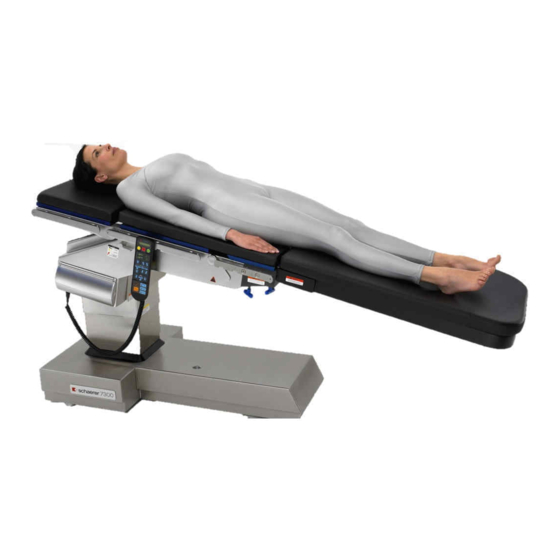
Model 7300 Modular
Surgery Table
Go To Table Of Contents
CA802000
Important
Information
Page 2
Installation
Page 4
Description
Page 7
Components
Overview
Page 8
Controls &
Indicators
Page 9
Operation
Page 12
Operator
Maintenance
Page 25
Calling For
Service
Page 26
Specifications &
Accessories
Page 26
Limited
Warranty
Page 31
Advertisement
Table of Contents

Related Manuals for Schaerer 7300

Summary of Contents for Schaerer 7300
- Page 1 Go To Table Of Contents Important Information Schaerer Medical USA, Inc. Page 2 Installation Installation and Operation Page 4 Manual Description Page 7 Model 7300 Modular Components Surgery Table Overview Page 8 Controls & Indicators Page 9 Operation Page 12...
- Page 2 Go To Table Of Contents Owner’s Product Identification (information that you will need to provide for servicing - key information is highlighted) Date of Purchase Serial Number Name of Owner / Facility / Department Model Number Name of Authorized SM-USA Dealer Telephone # of Authorized SM-USA Dealer Address of Authorized SM-USA Dealer MODEL...
-
Page 3: Table Of Contents
CONTENTS IMPORTANT INFORMATION ....................2 Scope and Purpose of This Manual ................2 Intended Use of Product ....................2 Safety Instructions ......................2 Explanation of Safety Symbols and Notes..............2 Transportation and Storage Conditions ................3 INSTALLATION ........................4 Unpacking........................4 DESCRIPTION........................7 Introduction ........................7 Features..........................7 COMPONENTS OVERVIEW ....................8 CONTROLS &... -
Page 4: Important Information
Scope and Purpose of This Manual This manual covers complete instructions for the installation, operation, and nor- mal care of the Model 7300 Surgery Table. It is intended that this manual be used by any medical personnel responsible for operating the surgery table dur- ing a medical procedure or performing operator level maintenance. -
Page 5: Transportation And Storage Conditions
RETURN TO TABLE Return To Table Of Contents OF CONTENTS EQUIPMENT ALERT Important Information Indicates an imminently or potentially hazardous situation which, if not avoided, will or may result in serious, moderate, or minor equipment damage. NOTE Amplifies an operating procedure, practice, or condition. Transportation and Storage Conditions •... -
Page 6: Installation
RETURN TO TABLE Return To Table Of Contents OF CONTENTS INSTALLATION Unpacking EQUIPMENT ALERT Installation To avoid damaging the table do not use a knife or other sharp ob- ject to open the table’s packaging. CA799300 FIGURE 1 1. Carefully cut the banding, remove the washer head nails, and lift off the cardboard shipping box. - Page 7 RETURN TO TABLE Return To Table Of Contents OF CONTENTS 4. Unbolt and remove the two metal straps (1) from around the table base. EQUIPMENT ALERT Do not operate the table until the shipping plug has been removed from the hydraulic reservoir and the vent plug has been installed in Installation its place.
- Page 8 RETURN TO TABLE Return To Table Of Contents OF CONTENTS 10. Unbolt and remove the wood block (7) located at the foot end base beneath the wood skid. WARNING The table w/ Pelvic Base (73001) weighs approximately 660 Installation lbs. (299.4 kg). Get an assistant to help remove the table from the shipping skid.
-
Page 9: Description
OF CONTENTS DESCRIPTION Introduction The 7300 Modular Surgical Table is primarily used for general surgery but can be easily adapted with various accessories to accomodate many different pro- cedures such as cardio vascular, neurosurgical, urology, obstetrics, gynecolog- ic, and orthopaedic. -
Page 10: Components Overview
RETURN TO TABLE Return To Table Of Contents OF CONTENTS COMPONENTS OVERVIEW The illustration below shows the location of the table’s major components and the chart below provides their descriptive name. Component Overview CA800300 DESCRIPTION OF COMPONENTS (Basic Table) 1. Hand Control 5. -
Page 11: Controls & Indicators
RETURN TO TABLE Return To Table Of Contents OF CONTENTS CONTROLS & INDICATORS The illustration below shows the hand control, foot control, and emergency override control . The chart that follows describes the function of each button or switch...Refer to “OPERATION” Section on each control before using them. NOTE The Reverse Position, patient’s head at opposite end from column, can only be ac-... -
Page 12: Operation
RETURN TO TABLE Return To Table Of Contents OF CONTENTS Ref. Control Function DISPLAY Electronically displays operational messages, status messages and error codes Main On / Off power switch Automatically locks table to floor ENABLE Displays position of table, NORMAL or REVERSE on hand control display. - Page 13 RETURN TO TABLE Return To Table Of Contents OF CONTENTS Ref. Control Function Lowers table surface. HEIGHT DOWN Tilts table surface to patient’s left side. Works in conjunction with Normal and TILT L Reverse Position buttons. Tilts side of table depending on selected patient position, Nor- mal or Reverse.
-
Page 14: Operation
The Model 7300 Modular Surgery Table has two basic positions, Normal and Reverse Position. You must press the appropriate, NORMAL or REVERSE PO- SITION to program the table for the desired position. -
Page 15: Head Section, Installation & Operation
RETURN TO TABLE Return To Table Of Contents OF CONTENTS • Head Section has a maximum weight capacity of 40 lbs. (18 kgs.). Leg Transfer Board (73002) is intended only for the support of a patient’s • legs and has a maximum distributed weight capacity of 150 lbs. (68 kgs.). •... -
Page 16: Possible Pinch Points
( ! ) on the the table. 1. I.A. Board (73004), CA801300 Leg Transfer Board (73002), or Split Leg (71111) and base. 7300 Operation 2. I.A. Board (73004), CA801400 Leg Transfer Board (73002), or Split Leg (71111) and floor. - Page 17 RETURN TO TABLE Return To Table Of Contents OF CONTENTS 4. Left Side Column CA801600 5. Above Pelvic Base (73001) and Back Section. 7300 CA801700 6. Below Pelvic Base (73001) and Back Section. Operation NOTE Should other ac- cessories be in-...
-
Page 18: Pendant Hand Control
Return To Table Of Contents OF CONTENTS Pendant Hand Control EQUIPMENT ALERT The Models 7100 and 7300 Hand Controls can- not be inter-changed between the ta- bles as they are not compatible to the programmed electronic functions. Function Buttons •... - Page 19 RETURN TO TABLE Return To Table Of Contents OF CONTENTS Power On Switch • The ENABLE/LOCK button is the main On/Off power switch. When depressed it will first lock ENABLE the table to the floor, then display the table posi- tion, Normal or Reverse.
-
Page 20: Foot Control
RETURN TO TABLE Return To Table Of Contents OF CONTENTS Foot Control Function Pedals NOTE The HAND CONTROL must be plugged into the table in order for the foot control to function. TABLE • The foot control has 6 control LATERAL pedals;... - Page 21 RETURN TO TABLE Return To Table Of Contents OF CONTENTS Power On Switch • When one of the Foot Control function pedals is depressed, the floor locks will engage before allowing a function to begin. After the table has been locked to the floor you can activate a function by pressing on its pedal.
-
Page 22: Emergency Override Panel
RETURN TO TABLE Return To Table Of Contents OF CONTENTS Emergency Override TRENDELENBURG Panel TABLE REVERSE TRENDELENBURG Function Buttons SEAT SYSTEM OVERRIDE • The Emergency Override Panel SEAT consist of 12 buttons. System DOWN Override, Disable, Lock, Unlock, Trendelenburg, Reverse Trendelburg, Height Up, Height Down, Lateral Tilt UNLOCK DISABLE... - Page 23 RETURN TO TABLE Return To Table Of Contents OF CONTENTS Unlock • The UNLOCK button releases the three main floor locks from the floor. It must be held, along with the System UNLOCK Override button for a minimum of 10 seconds in order to completely retract the floor locks.
-
Page 24: Hand Control Display Messages
RETURN TO TABLE Return To Table Of Contents OF CONTENTS Hand Control Display Messages Messages will be displayed on the Hand Control whenever the Hand or Foot controls are operated. No messages will appear when using the Emergency Override Panel. Display •... -
Page 25: Operator
RETURN TO TABLE Return To Table Of Contents OF CONTENTS LOCKING FLOOR Indicates the floor locks are being engaged. FLOOR LOCKED Indicates the floor locks are engaged. UNLOCKING FLOOR Informs the operator the floor locks are being disengaged. ON WHEELS Indicates the table is on its wheels and is mobile. -
Page 26: Operator
RETURN TO TABLE Return To Table Of Contents OF CONTENTS REFLEX Indicates the table is being moved to a reflex position. (Reflex is not available in the Reverse Position). RETURN TO LEVEL Informs the operator the entire table top is being moved to a level position. RECHARGE BATTERY / PLUG CORD IN NOW Informs the operator the battery charge has fallen below 1/6 of the capacity and that it is imperative that the power cord be plugged in immediately to allow the... -
Page 27: Operator Maintenance
RETURN TO TABLE Return To Table Of Contents OF CONTENTS OPERATOR MAINTENANCE Preventive Maintenance Schedule The following preventive maintenance schedule should be followed. If a prob- lem is detected, refer to the troubleshooting section of this manual. FREQUENCY ACTIVITY After each proce- Clean the upholstery and table top boards after each procedure dure with a mild soap and water solution. -
Page 28: Calling For Service
RETURN TO TABLE Return To Table Of Contents OF CONTENTS CALLING FOR SERVICE If you are having a problem or have a question, refer to the inside front cover of this manual and call your dealer. Make sure that you have the information that is highlighted on the inside front cover of this manual available especially the Model and Serial Number of the table. -
Page 29: Options And Accessories
Battery Power Output ...... 24 VDC, 18 amp-hours Electrical Requirements ....110-120 VAC, 60 HZ, 2 amp, single phase Options and Accessories For illustrations, proper set-up and application of the accessories refer to the Model 7300 Technique Manual. Accessory Name Order Number •... - Page 30 RETURN TO TABLE Return To Table Of Contents OF CONTENTS • Horizontal Perineal Post ....10824 (requires Ortho. Pelvic Base, 73007) • Tibia Extender ........ 10825 (requires Ortho. Pelvic Base, 73007) • Well Leg Support, siderail mount..10830 (includes Siderail Socket and Articu- ............
- Page 31 Drain Pan ........73003 (requires a Pelvic Base, 73001) • Image Amplification (IA) Extension w/ Cushion (55 in.) ..73004 • X-ray Top, 7300 ....... 73005 Specifications • Removable Back Section w/ Pad & Accessories (Neuro) ..........73006 (used with 71088 Neuro Headrest or Standard Table Headrest) •...
- Page 32 RETURN TO TABLE Return To Table Of Contents OF CONTENTS • Traction Unit........73010 (requires Abductor Bars, 73008; ............Abductor Bar Clamp, 73009; ............Traction Unit Exten., 73011) • Traction Unit Extension ....73011 (requires Abductor Bar Clamp, ............73009) •...
-
Page 33: Limited Warranty
OF CONTENTS LIMITED WARRANTY SCOPE OF WARRANTY Schaerer MEDICAL USA Inc. warrants to the original purchaser its new Surgical products and components (except for components not warranted under Exclusions) manufactured by SM-USA to be free from defects in material and workmanship under normal use and service. - Page 34 RETURN TO TABLE Return To Table Of Contents OF CONTENTS NOTES:...
- Page 35 Return To Table Of Contents...
- Page 36 RETURN TO TABLE Return To Table Of Contents OF CONTENTS Schaerer MEDICAL USA, Inc., 675 Wilmer Avenue, Cincinnati, Ohio 45226 U.S.A. 800-755-6381 FAX 513-561-0195 © Schaerer Medical USA Inc. 503-0343-00 Rev. F (8/19/2013)
Need help?
Do you have a question about the 7300 and is the answer not in the manual?
Questions and answers