Table of Contents
Advertisement
©2004 GE Inspection Technologies, LP
50 Industrial Park Road
Lewistown, PA 17044
Phone: +1 (717) 242-0327
Fax: +1 (717) 242-2606
www.GEInspectionTechnologies.com
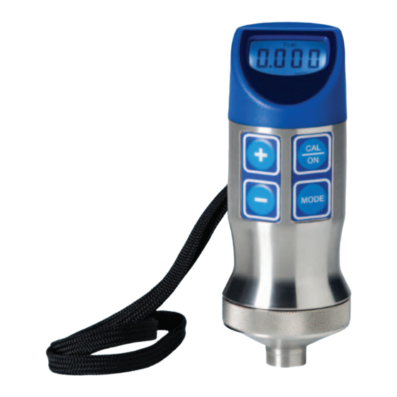
PocketMIKE
Operating Manual
021-002-279
GE Inspection Technologies GmbH
Robert-Bosch-Straße 3
D – 50354 Hürth
Phone: +49 (0) 2233 60111
Fax.: +49 (0) 2233 601402
Advertisement
Table of Contents

Related Manuals for StressTel PocketMIKE


Summary of Contents for StressTel PocketMIKE
-
Page 1: Operating Manual
PocketMIKE Operating Manual 021-002-279 ©2004 GE Inspection Technologies, LP GE Inspection Technologies GmbH 50 Industrial Park Road Robert-Bosch-Straße 3 Lewistown, PA 17044 D – 50354 Hürth Phone: +1 (717) 242-0327 Phone: +49 (0) 2233 60111 Fax: +1 (717) 242-2606 Fax.: +49 (0) 2233 601402... - Page 3 PocketMIKE Operating Manual version 1.0...
- Page 5 Operators must understand: Soundwave propagation theory. ◆ Effects of the sound velocity of the test material. ◆ Behavior of the sound wave where two different materials ◆ are in contact. Areas covered by the sound beam. ◆ PocketMIKE Operating Manual Page i...
- Page 6 Thickness measuring error is minimized by ensuring that the sound velocity to which the instrument is calibrated is the sound Page ii PocketMIKE Operating Manual...
- Page 7 The specified range of the trans- ducer must include the complete range of thicknesses to be tested. The temperature of the material to be tested must be within the transducer’s temperature range. PocketMIKE Operating Manual Page iii...
- Page 8 This thickness should be determined by calibrating the PocketMIKE on reference blocks that represent the complete range of possible thicknesses that may be encountered in testing. This is...
- Page 9 The result is the thickness of the material. The figure below illustrates the pulse-echo principle of ultrasonic thickness measurement. V-Path of Dual Pulse Probe Acoustic Zero Backwall Echo Dual Element Thickness Measurement PocketMIKE Operating Manual Page v...
- Page 10 Page vi PocketMIKE Operating Manual...
-
Page 11: Table Of Contents
6.4 Test Specimens with Curved Surfaces ............22 Chapter 7: Troubleshooting Guide ........... 25 Chapter 8: Warranty and Repair ............27 8.1 Warranty ......................27 8.2 Service ......................29 Chapter 9: Appendix ................31 Index ....................33 PocketMIKE Operating Manual Page vii... - Page 12 Page viii PocketMIKE Operating Manual...
-
Page 13: Chapter 1: Getting Started
Getting Started To begin using your PocketMIKE, you need only install a battery in the instrument and power it on. 1.1 Installing the Battery The instrument is powered by one “AA” size Alkaline ◆ battery. An alkaline battery will provide approximately 80 hours of ◆... -
Page 14: Powering On The Instrument
If the instrument is uncoupled and no keys are pressed for three minutes, the instrument will automatically power off. Page 2 PocketMIKE Operating Manual... -
Page 15: Chapter 2: Quick Help For Interpreting The Keypad And Display Screen
Quick Help for Interpreting the Keypad and Display Screen PocketMIKE controls and settings are displayed in the instrument’s screen and adjusted using various combinations of key presses. This chapter identifies the display screen’s features, the keypad functions, and the general display structure. Topics covered include: Keypad Operations (section 2.1) -
Page 16: Keypad Operations
Simultaneous pressing and HOLDING these keys activates and deactivates SAFE mode in which most instrument controls are disabled (section 3.7) Launches and ends the Velocity Calibration process and activates Backlight Adjustment mode (sections 3.3 and 3.1) Page 4 PocketMIKE Operating Manual... -
Page 17: Display Indicators
2.2 Display Indicators The PocketMIKE display (Figure 2-2) includes indicators (icons) around its perimeter and text or numerical values in its center. Indica- tors and other display contents vary in response to instrument settings, key presses, and measurement status. The following is a summary of display indicators. -
Page 18: Types Of Display Screens
Instrument memory is corrupted. Return for service. Calibration mode for sound velocity is active. Thickness may be calibrated. 2.3 Types of Display Screens The PocketMike offers three general display screen modes, similar to the three shown below: Thickness Measurement Display (Figure 2-3) ◆... - Page 19 See sections 3.2 and 3.3 for more details related to instrument calibration. FIGURE 2-5—Pressing twice (when operating in Thickness Measurement mode) launches the Backlight Adjustment mode. Pressing sets backlight to On, OFF, or Auto (section 3.1). PocketMIKE Operating Manual Page 7...
- Page 20 Page 8 PocketMIKE Operating Manual...
-
Page 21: Chapter 3: Setting Up The Instrument
NOTE: Before using this instrument, read the “Important Notices” at the beginning of this manual, and Chapter 6 — Application Consider- ations, for important information on test conditions that affect measure- ment results. PocketMIKE Operating Manual Page 9... -
Page 22: Adjusting The Display's Brightness (Backlight)
The backlight remains illuminated for approximately 4 seconds after which it auto- matically extinguishes. It will re-illuminate with the next key press or coupling. Page 10 PocketMIKE Operating Manual... -
Page 23: Thickness Calibration
Best results are achieved with a standard that is slightly thicker than the thick- est expected test piece. Uncouple when reading is stable then press to adjust reading to nominal value. FIGURE 3-1—Thickness Calibration Procedure PocketMIKE Operating Manual Page 11... -
Page 24: Velocity Calibration
A table of approxi- mate sound velocities for various materials can be found in Chapter 9. FIGURE 3-2—Velocity Calibration Procedure Page 12 PocketMIKE Operating Manual... -
Page 25: Setting The Measurement Units And Resolution
Note that the orientation of other on-screen indicators do not change. A press of the key will return the display to its normal orientation and enter velocity calibra- tion mode. PocketMIKE Operating Manual Page 13... -
Page 26: Replacing The Probe
The probe and locking ring are replaced as an assembly. Refer to Figure 3-3 for the probe replace- ment procedure. Always recalibrate the instrument after the probe is replaced or removed. FIGURE 3-3—Probe Replacement Page 14 PocketMIKE Operating Manual... -
Page 27: Disabling Instrument Adjustment Controls
3.8 Rotating the Display The plastic display housing on the top of the PocketMike can be rotated through 180 degree of motion. To rotate the display housing grasp the PocketMike in one hand while gently turning the display housing. - Page 28 Page 16 PocketMIKE Operating Manual...
-
Page 29: Chapter 4: Measuring Thickness
Measuring Thickness The PocketMIKE measures thickness in units of inches or mm. Read the following notices and instructions before measuring thickness. NOTE: The instrument is designed to measure materials with surface temperatures of up to 100°C. However, the instrument’s internal elec- tronics should not be allowed to reach temperatures above 60°C for ex-... - Page 30 Refer to Figure 4-1 to interpret display indicators. FIGURE 4-1—Thickness Measurement Mode NOTE: Only couplants approved by GE Inspection Technologies should be used. Other couplants, e.g. oil, may affect the instrument's functional- ity or cause damages! Page 18 PocketMIKE Operating Manual...
-
Page 31: Chapter 5: Specifications And Declaration
-20°C to +60°C (-4°F to +140°F) Probe Surface Temperature -10°C to +100°C (10°F to +212°F) Maximum coupling time 3 sec at 100°C (212°F). One minute cool down. Power Source Qty 1, 1.5 VDC, AA Alkaline Battery PocketMIKE Operating Manual Page 19... -
Page 32: Ec Declaration Of Conformity
The Group 2 comprises all ISM equipment (industrial, scientific, and medical radiofrequency equipment) in which RF energy is intentionally generated and/or used as electromagnetic radiation for the purpose of material treatment, as well as EDM and arc-welding devices. Page 20 PocketMIKE Operating Manual... -
Page 33: Chapter 6: Application Considerations
The following table expresses accuracy variations for some common materials. Actual accuracy may be different. Aluminum +/– 2% Cast Iron +/– 8% Steel +/– 0.5% Nylon +/– 10% NOTE: These specifications are intended only as a general guide. PocketMIKE Operating Manual Page 21... -
Page 34: Flaws In The Specimen Being Tested
6.2 Flaws in the Specimen Being Tested If, during testing, the PocketMIKE suddenly reads a value which is much thinner than the apparent thickness of the part, it may be reading the distance to a flaw in the test piece, rather than the distance to the backwall. - Page 35 When using a flat dual probe, position the crosstalk barrier at a right angle to the long axis of the part, as shown in Figure 6-1. PROBE CONTACT CROSSTALK FÄCE BARRIER LONG AXIS OF TUBE FIGURE 6-1—Crosstalk Barrier Orientation PocketMIKE Operating Manual Page 23...
- Page 36 Page 24 PocketMIKE Operating Manual...
-
Page 37: Chapter 7: Troubleshooting Guide
Troubleshooting Guide Should your instrument malfunction, refer to the guidelines that correspond to the problem you’re experiencing: PocketMIKE Operating Manual Page 25... - Page 38 Page 26 PocketMIKE Operating Manual...
-
Page 39: Chapter 8: Warranty And Repair
GE Inspection Technologies shall be found to its reasonable satisfaction to have been thus defective. THIS REMEDY IS EXPRESSLY SUBSTITUTED FOR ANY AND ALL OTHER REMEDIES POSSIBLE UNDER THE UNIFORM COMMERCIAL CODE, STATE, COMMON OR STATUTORY LAW OR OTHERWISE. PocketMIKE Operating Manual Page 27... - Page 40 IMPLIED OR EXPRESSED WARRANTY OF MERCHANTABIL- ITY, SUITABILITY OR FITNESS FOR A PARTICULAR PURPOSE and GE Inspection Technologies neither assumes nor authorizes another to assume any liability in connection with such equipment, except as provided above. Page 28 PocketMIKE Operating Manual...
-
Page 41: Service
50 Industrial Park Road Lewistown, PA 17044 U.S.A. Phone: +1 (717) 242-0327 Fax.: +1 (717) 242-2606 GE Inspection Technologies GmbH Robert-Bosch-Straße 3 D – 50354 Hürth Germany Phone: +49 (0) 2233 601111 Fax.: +49 (0) 2233 601402 PocketMIKE Operating Manual Page 29... - Page 42 All products should be sent back in their original carry cases, or wrapped in bubble wrap or other available packaging material. GE Inspection Technologies warrants all repairs for a full 90 days. Page 30 PocketMIKE Operating Manual...
-
Page 43: Chapter 9: Appendix
NOTE: This information is provided for the convenience of the user. GE Inspection Technologies assumes no responsibility for inaccuracies. Actual velocities depend on exact composition, temperature, and processing of each material. PocketMIKE Operating Manual Page 31... - Page 44 Page 32 PocketMIKE Operating Manual...
-
Page 45: Index
Brightness ....................10 CAL ......................6 Calibration ....................11 Curved Surfaces ..................22 Display ....................... 5 donE ......................6 EC Declaration of Conformity ............... 20 FAIL ......................6 Features ....................19 Flaws in the Specimen ................22 PocketMIKE Operating Manual Page 33... - Page 46 Repair ....................... 29 Resolution ....................13 Reverse the display ................13 SAFE ......................15 Service ..................... 29 Specifications ..................19 Surface ..................... 22 Temperature .................... 17 Thickness ....................17 Thickness calibration ................11 Troubleshooting ..................25 Page 34 PocketMIKE Operating Manual...
- Page 47 Units of measurement ................13 Velocity calibration ................. 12 Warranty ....................27 PocketMIKE Operating Manual Page 35...
Need help?
Do you have a question about the PocketMIKE and is the answer not in the manual?
Questions and answers