Advertisement
Table of Contents
- 1 Table of Contents
- 2 Important Notice
- 3 Theory of Operation
- 4 Diagram of System
- 5 Specifications
- 6 Initial Setup
- 7 Operation
- 8 T-Mike Programmable
- 9 T-Mike Basic
- 10 Helpful Hints on Operation
- 11 Maintenance and Troubleshooting
- 12 Warranty and Service
- 13 Appendix A
- 14 Appendix B
- Download this manual
Advertisement
Table of Contents

Related Manuals for StressTel T-MIKE E


Summary of Contents for StressTel T-MIKE E
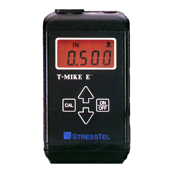
- Page 1 T-MIKE E/P/B OPERATION MANUAL...
- Page 3 T -MIK E E /P /B OP E R AT ION MANUAL 021-002-147 R E V H VERSION 4 2005 G E Ins pection Technologies , LP 50 Indus trial P ark R d. Lewis town, PA 17044 US A P : 717.242.0327, F : 717.242.2606 www.G E InspectionTechnologies.com...
-
Page 5: Table Of Contents
Table of Contents IMPORTANT NOTICE......................... 1 THEORY OF OPERATION......................5 DIAGRAM OF SYSTEM ......................7 SPECIFICATIONS ........................9 INITIAL SETUP........................... 11 OPERATION ..........................13 T-MIKE PROGRAMMABLE......................19 T-MIKE BASIC...........................21 HELPFUL HINTS ON OPERATION.....................23 MAINTENANCE AND TROUBLESHOOTING ................25 WARRANTY AND SERVICE....................... 27 APPENDIX A..........................29 APPENDIX B. -
Page 7: Important Notice
Important Notice he following information must be read and understood by any user of a GE Inspection Technologies ultrasonic thickness gauge. Failure to follow these instructions can lead to errors in thickness measurements or other test results. Decisions based on erroneous results can, in turn, lead to property damage, personal injury or death. General Warnings Proper use of ultrasonic test equipment requires three essential elements: ·... - Page 8 • Effects of the sound velocity of the test material • Behavior of the sound wave where two different materials are in contact • Areas covered by the sound beam More specific information about operator training, qualification, certification and test specifications is available from various technical societies, industry groups, and government agencies.
- Page 9 Calibration of Sound Velocity The principle of operation of an ultrasonic thickness gauge is that the instrument measures the time of flight of an ultrasonic pulse through the test piece and multiplies this time by the velocity of sound in the material. Thickness measuring error is minimized by ensuring that the sound velocity to which the instrument is calibrated is the sound velocity of the material being tested.
- Page 10 Use of Couplants Operators must be familiar with the use of ultrasonic couplants. Testing skills must be developed so that couplant is used and applied in a consistent manner to minimize variations in couplant layer thickness and errors in test results. Calibration and actual testing should be performed under similar coupling conditions, using a minimum of couplant and applying consistent pressure on the transducer.
-
Page 11: Theory Of Operation
A. Ultrasonic Wave The T-Mike E measures the thickness of a material by launching an ultrasonic wave into the material using an ultrasonic transducer and calculating the time for the wave to pass through the material and reflect back to the transducer. - Page 12 To maximize measurement accuracy select a calibration piece that has the same shape and approximate thickness as the work piece being measured. Re-calibrate the T-Mike E when the temperature of the work piece changes 5 o C or more from the calibration piece.
-
Page 13: Diagram Of System
Chapter II Diagram of a System COUPLANT USED BETWEEN THE PROBE AND BLOCK PROBE BLOCK T-MIKE E... -
Page 14: Specifications
Chapter III Specifications T-MIKE E/P/B SPECIFICATIONS Approximate Measuring range 0.040 - 19.999” (Material and Application Dependent) Resolution 0.001 in. Display Measurement Backlit 4 ½ digit Al- 0 o F to 200 o F lowable Surface Temperature Cable Length 4 ft. -
Page 15: Initial Setup
Backlight On/Off When the CAL key is first released the T-Mike E will display the words ON or OFF to indicate the status of the backlight. The backlight setting can be selected by pressing the UP or DOWN arrow key. - Page 16 It is recommended that the lock feature be used when supervising personnel wish to prevent unauthorized change of the calibrated velocity. Pressing the CAL key a final time completes the SETUP procedure and returns the T-Mike E to the measurement mode.
-
Page 17: Operation
Press this key to turn the T-Mike E on. The unit will display a reading of zero. The T-Mike E is now ready for measurement or calibration. In order to compensate for any change in the ultrasonic transducer, a PROBE ZERO function should be performed at this point. - Page 18 Apply a drop of couplant to the representative piece of material of known thickness. This piece is called the sample. Place the probe in steady contact with the surface of the sample. The T-Mike E will display a thickness reading using the last calibrated velocity.
- Page 19 Press the CAL key. The arrow symbols will appear in the upper left portion of the display indicating the UP/DOWN arrow keys are active. Press the CAL key a second time. The display on the T-Mike E will display the current velocity and the appropriate units of measure.
- Page 20 Or if metric units are selected: Use the UP and DOWN arrow keys to scroll the velocity to the known velocity of the material. Note that when these keys are held continuously, the speed that the velocity changes will increase, making DOWN it easy to make the large adjustments for materials such as plastic and aluminum.
- Page 21 This will alert the operator that the measurement may be subject to error, and steps should be taken to improve the transducer coupling or position. If no echo is detected for a period of 4 ½ minutes, the T-Mike E will automatically switch to its low power or dormant state as indicated by the display becoming blank.
- Page 22 When the battery level falls below the minimum allowable level the T-Mike E will turn off and not allow further operations until batteries are replaced or recharged. Replacing or Recharging Batteries The T-Mike E comes standard with 4 AA alkaline batteries. The user may elect to use rechargeable NiCad AA batteries that can be inserted as a direct replacement of the alkaline cells.
-
Page 23: T-Mike Programmable
To Program From a T-Mike E Set the T-Mike E in the desired mode by holding down the CAL key while turning on the power. Now calibrate the sound velocity of the T-Mike E to the desired sound velocity. Turn off both gauges. Connect the special cable between the two data/charger ports. - Page 24 T-Mike Programmable, it will momentarily display the calibrated sound velocity. Test the T-Mike Programmable on a material sample to verify that it reads the correct thickness. Special Cables From a T-Mike E to T-Mike Programmable Part # 062-500-055 From IBM Compatible Computer to T-Mike Programmable...
-
Page 25: T-Mike Basic
The T-Mike Basic has five operator selectable materials (steel, aluminum, stainless steel, cast iron, and plexiglass) with preset sound velocities. One custom material ca be programmed by connecting the T-Mike B to an IBM compat- ible computer running special software, or from a T-Mike E. In either case, a special cable is required. Material Selection First follow the above PROBE ZERO procedure to calibrate the delay of the ultrasonic transducer being used. - Page 26 TO PROGRAM FROM A T-MIKE E Set the T-Mike E in the desired mode by holding down the CAL key while turning on the power. Now calibrate the sound velocity of the T-Mike E to the desired sound velocity. Turn off both gauges. Connect the special cable between the two data/charger ports.
-
Page 27: Helpful Hints On Operation
Helpful Hints on Operation Backlight The T-Mike E features a backlit LCD display. The display illuminates when an echo is detected. Using the backlight will significantly reduce battery life. Therefore, you may wish to deactivate the backlight when using the T-Mike E in a well-lit environment. -
Page 28: Maintenance And Troubleshooting
Display The LCD is made of glass and is one of the most fragile components of the T-Mike E. It may break if dropped. This LCD must be replaced by a factory trained technician. DO NOT clean the surface of the display with any solvents or... -
Page 29: Warranty And Service
Chapter X Warranty and Service Instrument and Transducer Warranty There are no warranties, expressed or implied by either distributor or the manufacturer on new equipment except the manufacturer’s warranty against defects in material and workmanship set forth below: GE Inspection Technologies warrants new instruments manufactured by GE Inspection Technologies and delivered to the original retail purchaser F.O.B. - Page 30 temperature that is not compatible with the materials of construction. - To any parts of an instrument or transducer, which, under normal usage, would not or are not expected to last the warranty period, i.e. “wear” items (i.e. batteries and cables). - To any instrumentor transducer, which have not been subject to proper care and maintenance.
-
Page 31: Appendix A
4700 Nickel 5600 The information is supplied for the convenience of the user and StressTel Corporation assumes no responsibility for inaccuracies. The actual velocity of the above material is dependent upon the exact composition, temperature, and processing of each material. -
Page 32: Appendix B
Appendix B... - Page 34 In two point calibration mode the automatic function of the probe zero block on the top of the T-Mike E is disabled.
- Page 35 In the setup menu, the user first sees the software revision displayed. Then the backlight on/off is shown, then IN/ MM, then CAL/LOC. The next press of CAL allows the user to scroll between one and two point calibration techniques. The display appears: Press Ó...
- Page 36 Couple the probe to the thinner calibration sample. Remove the probe and adjust the reading to agree with the known thickness by pressing á or â. When this reading is correct press [CAL]. The gage will display: Couple the probe to the thicker calibration sample. Remove the probe and adjust the reading to agree with the known thickness by pressing á...
Need help?
Do you have a question about the T-MIKE E and is the answer not in the manual?
Questions and answers