Table of Contents
Advertisement
Quick Links
Advertisement
Table of Contents

Summary of Contents for Golden engineering XRS-3
- Page 1 XRS-3 X-RAY SOURCE OPERATOR’S MANUAL...
-
Page 2: Table Of Contents
CONTENTS ITEM PAGE INTRODUCTION................. 2 WARNINGS..................2 DUTY CYCLE……………………………………………………………. PHYSICAL DESCRIPTION..............3 HIGH VOLTAGE PULSER/TUBEHEAD........…….. 3 BASE....................BATTERY PACK……................ BATTERY CHARGER................ CONTROL MODULE…………………………........CABLE CONNECTOR DIAGRAM………………………………………. 5 DESCRIPTION OF OPERATION............6 BLOCK DIAGRAM………………………………………………………… 6 OPERATING INSTRUCTIONS............7 OPERATING PRECAUTIONS............…. 7 EXCLUSION ZONE………………………………………………………. -
Page 3: Introduction
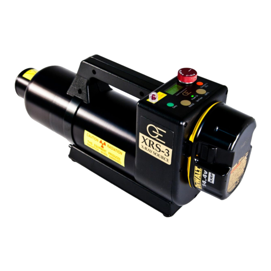
XRS-3 is a pulsed x-ray device that produces x-ray pulses of very short duration (50 nanoseconds). It produces a relatively low dose rate comparable to a 0.25 ma constant potential machine. The energy produced by the XRS-3 is up to 270KVP, which makes it possible to radiograph up to one (1) inch (2.54 cm) of steel. -
Page 4: Physical Description
85 degrees are available. BASE. The base of the XRS-3 contains the base plate, tripod mount, tripod mount release button, and identification label. The tripod mount contains threaded ¼-20 insert that can be attached to any standard camera tripod. -
Page 5: Control Module
RED X-RAY PULSING LIGHT: Blinks after time delay button or remote cable button is pressed to warn that the XRS-3 is going to pulse. The light stays on continuously while the XRS-3 is pulsing. This is a failsafe warning light. If the light does not work the X-ray unit will not pulse. -
Page 6: Cable Connector Diagram
XRS-3 REAR VIEW/CABLE CONNECTOR PIN # DESCRIPTION +5 VOLTS 100 ma MAXIMUM REMOTE SWITCH REMOTE SWITCH – NO DELAY X-RAY ON SIGNAL COMMON 0 VOLTS REMOTE CONNECTOR: LEMO EPG.0B.305.HLN MATING CABLE PLUG: LEMO FGG.0B.305.CLAD 56Z PIN 2 PIN 5 Remote switch inputs are activated when grounded. -
Page 7: Description Of Operation
50 nanoseconds in duration is applied across the x-ray tube generating x-rays. The closing of the High Voltage Switch produces an audible pulsing sound. The XRS-3 cannot produce x-rays without the pulsing sound so it serves as an additional warning the XRS-3 is functioning. -
Page 8: Operating Instructions
8. Press the UNITS BUTTON and EMERGENCY STOP BUTTON simultaneously to lock in pulse setting. XRS-3 will retain locked in pulse setting until it is changed. Select ones digit Enter ones value (0-9) -
Page 9: Remote Cable Option
Underexposure can be corrected by increasing the number of pulses and/or decreasing the distance between the imaging medium and the XRS-3. Overexposure can be corrected by reducing the number of pulses and/or increasing the distance between the imaging medium and XRS-3. -
Page 10: Software
➢ The condition indicates a low battery. ➢ The XRS-3 will be inoperable until the key switch is turned off and on, or the battery is replaced. If there is more than one second between two consecutive pulses. -
Page 11: Troubleshooting
8.0 TROUBLESHOOTING SYMPTOM TEST ACTION No “power on” light -Check battery voltage - Replace or charge battery -Check battery connection - Make sure battery is securely attached and battery clips are not bent or broken. Power on lights, but X-ray -Check the battery voltage. -
Page 12: Fuse Replacement
FUSE REPLACEMENT Requires T-10 Torx driver & needle nose pliers. 1. Remove the back plate. Remove the 5 screws in the back plate then pull the back plate off slowly maneuvering the battery terminal connecting wires through the opening in the oscillator board. 2. -
Page 13: Head Replacement
STEP 1 2 AMP FUSE STEP 4 15 AMP FUSE POWER TRANSISTORS STEP 2 STEP 2 SIGNAL WIRE X-RAY ON / FEEDBACK SWITCH Figure 7:Oscillator Board STEP 3 HEAD REPLACEMENT Requires a small flat head screw driver. 1. Remove the boards as instructed above. 2. -
Page 14: Warranty
Batteries may be returned to Golden Engineering for disposal. 10.0 WARRANTY Golden Engineering, Inc. warrants XRS-3 X-ray unit made and sold by it or its authorized representatives to be free of defects in materials and workmanship for a period of twelve (12) months from the date of shipment to the end user. -
Page 15: Specifications
-10 to 120 degrees F (-23 to 50 degrees C) Maximum duty cycle 200 pulses every 4 minutes (3000 pulses per hour) Warm-up None required 12.0 SPARE PARTS AND ACCESSORIES FOR THE XRS-3 ITEM PART NUMBER Thumbwheel Key 2002000 Flat key 5951020 DeWalt Battery 14.4v DC 9091...


Need help?
Do you have a question about the XRS-3 and is the answer not in the manual?
Questions and answers