Advertisement
Quick Links
Advertisement

Subscribe to Our Youtube Channel
Related Manuals for Hyperdrive Pro 3 Solid Chassis

Summary of Contents for Hyperdrive Pro 3 Solid Chassis
- Page 1 Hyperdrive Pro 3 Solid Chassis © 2007 Hyperdrive Racing Published September 2006...
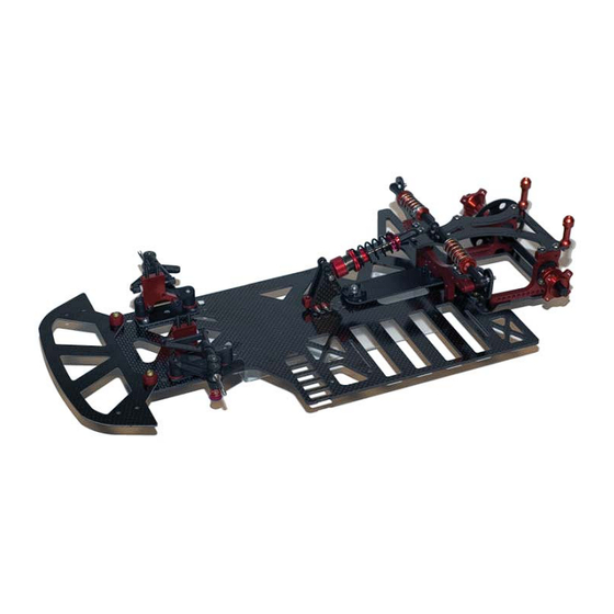
- Page 2 Introduction Congratulations! You now own a state of the art 1/10 scale oval race car. The Hyperdrive Pro 3 Solid Chassis has gone through months of testing by our factory drivers to insure that you get a car that has maximum performance and adjustability built in.
-
Page 3: Step 1 - Front Bumper Installation
Step 1 - Front Bumper Installation Using part numbers FB-7045 (Woven Bumper), HD-7307 (Solid Chassis) locate two 8-32 fl at head screws and two 8-32 hex nuts (the 8-32 hardware is located in the bag containing the Associated #8400 Front Suspension Kit). Install the 8-32 fl... - Page 4 Step 2 - Locator Plate Installation Secure the Narrow Locator Plate (LP-7050) in the front position of the mounting holes on the chassis using four 5/16” FH screws and four aluminum 4-40 lock nuts.
- Page 5 Step 3 - Front Suspension Assembly Assemble the front suspension (8400-003) as detailed in the Associated 8400 Front Suspension Kit instruction sheet, replacing the stock plastic castor blocks with HY-8060R Red Aluminum caster blocks. Insert four 8-32 screws through the bottom of the chassis and narrow locator plate.
- Page 6 Step 4 - T-Plate Assembly Locate the T-plate (HP-1516), 2 Tefl on Coated Aluminum Pivot Balls (HY-8376), 8-button head mounting screws (2-56 x 0.25” lg) and the plastic pivot housings Place one of the pivot balls into one side of the socket. Then place the other half of the socket onto the ball and align the four screw mounting holes.
- Page 7 Step 5 - Rear Pod Assembly Locate the Bottom Plate (HD-7365), Right Side Pod Plate (HD-7340), Left Side Pod Plate (HD-7341), three .075 black t-plate spacers, four 1/4” FH screws, three 3/8” FH screws and 3 4-40 Aluminum lock nuts. Insert the three 3/8”...
- Page 8 Step 6 - Nerf Wing Installation Locate the Nerf Wing (HD-7303), two 5/16” FH screws, and two 4-40 aluminum lock nuts. Insert two 5/16” FH screws through the bottom of the chassis on the right hand side to mount the Nerf Wing. Place the nerf wing over the screws, and attach with two 4-40 locknuts.
- Page 9 Step 7 - Pod Installation Using the rear pod from step 5, insert one 1/2” FH screw through the bottom of the chassis. Place the front t-plate pivot ball over the screw, and secure with a 4-40 lock nut. Refer to fi gure 7 for proper placement. Slider Chassis Pictured...
- Page 10 Step 8 - Cross Brace and Center Shock Mount Installation Assemble the Center Shock Mount with the supplied SHC screws and 4-40 lock nuts as shown in fi gure 9. Secure the fi nished shock mount to the chassis with two 1/4” FH screws.
- Page 11 Step 9 - Body & Side Shock Mount Installation Locate the Shock & Body mounts (HD-7320), 2 Aluminum Ball studs, 8 1/4” BH screws, 4 .020 shims, and 2 4-40 lock nuts. Install a ball stud from the front of the shock mount using the second hole down from the top.
- Page 12 Step 10 - Top Plate Installation Locate the Center/Offset top plate (HD-7315), four 1/4” BH screws, three aluminum ball studs, and three 4-40 lock nuts. From the top of the top plate, insert one ball stud in the right most forward hole and secure it with a 4-40 lock nut from the bottom of the plate.
- Page 13 Assemble the Center shock (TAM-1000R) and the side shocks (SK-1000R) as per the instructions included with each shock. Hyperdrive suggests using high quality silicon shock oils in your shocks. A good starting point on the shock setup is 40 wt. in the center shock and 30 wt.
-
Page 14: Step 12 - Bearing Carrier Installation
Step 12 - Bearing Carrier Installation Locate the Ride Height Set (PP-2312) and choose the two adjusters with the holes in the center. Depending on the Final ride height of your car these may have to be changed. Note: Always install the same adjuster on each side of the pod in the same orientation. - Page 15 Step 13 - Rear Axle / Differential Assembly Locate the following for the Diff and Rear Axle assembly: Rear Axle (RA-0401), Offset Diff Hub (RA-2405R), Left Side Wheel Hub (RA-2410R), Micro-Washers (RA-0403), Spur Gear Bearing (RA-0408-NF), Rear Axle and Right Hub Bearings (RA-0408), Diff Centering Set (RA-0411R), Diff balls (DB-0901), Diff Rings (DR-1002) and Spur Gear (SG-0116).
-
Page 16: Step 14 - Axle Installation
Step 14 - Axle Installation Place three micro washers over the free end of the axle. Insert through the right bearing carrier. Place one more micro washer, and two wide axle spacers, and the left side clamping hub on the free end of the axle and tighten assembly. -
Page 17: Final Assembly
Final Assembly Finally install your electronics, Motor, Battery, Tires and Body. The location of your Steering Servo, Electronic Speed Control and Receiver are entirely up to you. Take great care when mounting these to the Chassis as their location effects the balance of the car. Also care should be taken when drilling, fi...
Need help?
Do you have a question about the Pro 3 Solid Chassis and is the answer not in the manual?
Questions and answers