Advertisement
www.premierhazard.co.uk
Features Overview :
100W / 60W Speaker Outputs
Interlock input
Day & night volume levels
Data output
Reverse polarity protection
Over voltage protection
Over Current protection
Approvals:
2004/104/EC as amended by (2009/16/EC)
Acoustic: KBA ABG , W
ECE REG 10.4
NPIA specification 5 (issue 11)
Premier Hazard Ltd., YO16 4SJ, http://www.premierhazard.co.uk,
Tel.: +44(0)113 239 1111, E-Mail: info@premierhazard.co.uk
© 2013 Premier Hazard ltd. A member of the Public Safety Equipment group of companies
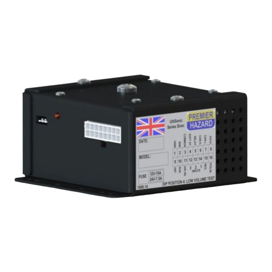
9004 Remote Mount Siren Amplifier
Installation Instructions
9004-12-DE1 & 9004-24-DE1
E
11 10R-04 7932
As part of our policy of continuous improvement we reserve the right to change
Sonic
Horn switch polarity detection
Relay driver output for horn bypass
Run input
Fault indication
Overheating protection
Under voltage protection
Speaker short circuit protection
25057
specifications without notice.
D00216-00-A
REL.39968
Advertisement
Table of Contents

Related Manuals for Premier Hazard 9004

Summary of Contents for Premier Hazard 9004
-
Page 1: Installation Instructions
As part of our policy of continuous improvement we reserve the right to change specifications without notice. Premier Hazard Ltd., YO16 4SJ, http://www.premierhazard.co.uk, D00216-00-A Tel.: +44(0)113 239 1111, E-Mail: info@premierhazard.co.uk REL.39968 © 2013 Premier Hazard ltd. A member of the Public Safety Equipment group of companies... - Page 2 Contents: Features overview Approvals Safety information Electrical Information Tone Information Fitting Information Dimensional Drawing In the Box Features description Wiring loom Information Software description Typical Installation diagram Description of Positive and Negative HRT detection Wiring a horn bypass relay Wiring day and night volume switching Wire size selection matrix Fault codes and Troubleshooting Safety Information:...
-
Page 3: Tone Information
Tone information: Tone specification DIN 14610 Fitting information: Leave room for airflow around the siren (approx. 50mm). Don’t place any wiring directly on the siren casing. The siren amplifier is not waterproof, so should be fitted in a suitable location. Siren amplifier dimensional drawing: 78.5... - Page 4 PH PN: ME005-000-12V or ME005-000-24V Note: an 11 Ohm impedance 100W speaker is required along with the siren amplifier to produce sound. Please see page 14 for further details on Premier Hazard speakers, speaker cowls and switch accessories. 9004 SERIES...
- Page 5 Features: Horn polarity detection – The siren amplifier detects if the horn is positive switched or negative switched on start up. The HRT wire (pin 9) should be connected to the switched side of the horn (see page 9 for full details). Data output –...
-
Page 6: Wiring Loom Information
Wiring Loom information: Pin No: Wire Colour: Function: Wire rating: Brown / white stipe Speaker 100W output – Speaker 60W output Brown Speaker common output Gray Not used on this version Blue Relay output (Positive output, 200mA max) Not connected No Function –... -
Page 7: Software Description
Software description: INTERLOCK The interlock input needs to be connected to a positive voltage source for the tone to be able to sound, such as a beacon interlock device. If not used connect to battery positive to enable tones. HORN / FOOTSWITCH INPUT Providing that the interlock input is connected to a positive voltage source, and that the siren isn’t already sounding. -
Page 8: Wiring A Horn Bypass Relay
Positive & Negative HRT detection: The Siren amplifier detects if the horn ring transfer is positive or negative switched at start up. If the HRT input senses a positive feed it must be a negative switched horn, if it doesn’t sense a positive feed it must be a positive switched horn. -
Page 9: Wire Size Selection Matrix
Day & Night Volume Switching Below are two different wiring possibilities for wiring a switch to control the siren output for day and night volume levels. Day and night switching using relay Day and night switching using SPDT Switch SPDT switch PH PN: 502 Note: SPDT switch can be used for both operations, when using SPDT switch it must be rated correctly for the current passing through it (6A). - Page 10 Fault Codes: When the siren amplifier detects a problem with its operation it flashes the fault LED on the front of the unit, fault patterns below. The fault light should be treated as a warning of improper operation and possible causes should be investigated. The trouble shooting table below may assist with this, note this is not intended to be an exhaustive list and is a guide only all work should be carried out by an electrically competent person.
- Page 11 NOTES:...
- Page 12 M – SPEAKER COWL ME005 SERIES Premier Hazard Ltd., YO16 4SJ, http://www.premierhazard.co.uk, Tel.: +44(0)113 239 1111, E-Mail: info@premierhazard.co.uk © 2013 Premier Hazard ltd. A member of the Public Safety Equipment group of companies A member of the Public Safety Equipment (PSE) group of...
Need help?
Do you have a question about the 9004 and is the answer not in the manual?
Questions and answers