Table of Contents
Advertisement
www.premierhazard.co.uk
Features Overview:
Personal Announce
30 Seconds Play / Record
60W/100W/200W outputs
Horn Ring Transfer of tones
Run
Air-horn Input
Ignition Input
Data logger output
Relay output for horn by-pass
Digital Audio Amplifier
Robust Construction
Approvals:
EMC:
Acoustic: KBA, W
Premier Hazard Ltd., YO16 4SJ, http://www.premierhazard.co.uk,
Tel.: +44(0)113 239 1111, E-Mail: info@premierhazard.co.uk
© 2013 Premier Hazard ltd. A member of the Public Safety Equipment group of companies
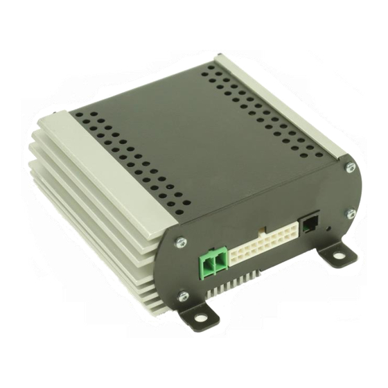
ShockWave
9005 Remote Mount Siren Amplifier
General Installation Instructions
Full backward compatibility with 8000 Series siren amplifier controllers
E
ECE REG 10.4,
11 10R-04 8014 NPIA specification 5 (issue 11)
25055
As part of our policy of continuous improvement we reserve the right to change
Radio Rebroadcast channel 1
Radio Rebroadcast channel 2
Multiple Siren Tones
HRT polarity detection
Interlock
sidelights
Negative inputs
Relay output for beacon control
CANBUS communication
Digital sound reproduction
Circuit protection
specifications without notice.
D00217-00-A
REL: 39983
Advertisement
Table of Contents

Related Manuals for Premier Hazard ShockWave 9005

Summary of Contents for Premier Hazard ShockWave 9005
-
Page 1: Features Overview
As part of our policy of continuous improvement we reserve the right to change specifications without notice. Premier Hazard Ltd., YO16 4SJ, http://www.premierhazard.co.uk, D00217-00-A Tel.: +44(0)113 239 1111, E-Mail: info@premierhazard.co.uk REL: 39983 © 2013 Premier Hazard ltd. A member of the Public Safety Equipment group of companies... -
Page 2: Table Of Contents
Contents: Features Overview Approvals Safety information Electrical Information Fitting Information In the box Product description Controller feature Function table Wiring loom Information Wire size vs distance selection matrix Features Ignition Interlock Speaker output Day and night volumes Horn ring transfer (HRT) / Footswitch Data output Relay output (for horn bypass) Relay output (for beacon control) -
Page 3: Electrical Information
Electrical Information: Operating Voltage range 12V model: 11V – 16V (use 25A fuse) Operating Voltage range 24V model: 22V – 32V (use 15A fuse) Speaker requirements: 11 Ohm impedance, 100W loudspeaker. Or 2 * 11 Ohm impedance, 100W loudspeakers connected in parallel. Radio rebroadcast 1 &... -
Page 4: Product Description
Product description: The 9005 siren amplifier is part of a modular approach to siren and vehicle lighting control. Various controllers can connect to the siren which allows various operational modes to be enabled whilst connected to the amplifier via a CANBUS enabled communication lead (see below for details). The tones and operational modes are selected by the controller see individual controller datasheets for available tones and features. -
Page 5: Controller Feature Function Table
Controller feature Function Table CONTROLLER MICROPHONE DIN SLOT PHASE 2 CONTROLLER & OPTION CONTROLLER CONTROLLER CONTROLLER MICROPHONE IMAGE PART No. SERIES CP1-9005-DV CP2-9005-DV CP3-9005-DV SERIES SERIES SERIES SERIES P.A. FUNCTION PLAY/RECORD FUNCTION RADIO RE-BROADCAST 1 RADIO RE-BROADCAST 2 SIREN TONE CONTROL RELAY OUTPUT DATA OUTPUT... -
Page 6: Wiring Loom Information
Wiring Loom information: View from rear of connectors Pin No Wire Colour: Function: Wire size: Battery input positive feed (28/0.3mm) 20A Black Battery negative return feed (28/0.3mm) 20A Brown Speaker Common 1.5mm (21/0.3mm) 10A 1.5mm (21/0.3mm) 10A Brown / white 100W / 200W 1.5mm (21/0.3mm) 10A... -
Page 7: Features
Features: Ignition The ignition feed always needs to be connected for the siren amplifier to operate. On some controllers the run input may be required to enable the tones to sound. The run input is active when it has a positive feed (this is a signal cable only). Interlock On some controllers and certain tones the interlock input may be required to enable the tones to sound. -
Page 8: Day And Night Volumes
Day and night volumes Below are two different wiring possibilities for wiring a switch to control the siren output for day and night volume levels. Day and night switching using relay Day and night switching using SPDT Switch SPDT switch PH PN: 502 Note: SPDT switch can be used for both operations, when using SPDT switch it must be rated correctly for the current passing through it (6A). -
Page 9: Relay Output (For Horn Bypass)
Relay output 1 (Horn Bypass) – This provides a 200mA positive output feed that can be used to connect to a separate relay (available separately) so that the Horn can be bypassed when the siren is operating. This output is active when either the tone is sounding or when the run input is selected. The diagram below shows how to connect the HRT input and relay output of the siren amplifier to additional components to act a horn by pass for either a positive or negative switched horn. -
Page 10: Play / Rec
Record and Playback Placing the 9005 compatible siren controller in the play mode allows up to 30 seconds of recorded message to be broadcast over the sirens speaker on a continuous loop. Pressing and holding the PTT button records from the microphone as long as the PTT is held ... -
Page 11: Fault Led
Fault LED – The siren amplifier has a fault LED incorporated into the front panel to aid debugging and troubleshooting of any detected faults. The LED will flash in different patterns to identify a particular fault as shown in the table below. The fault light should be treated as a warning of improper operation and possible causes should be investigated. -
Page 12: Typical Installation Diagrams
TYPICAL INSTALLATION DIAGRAMS 9005 & STC/MTC (STC SHOWN) D00217-00-A REL: 39983... - Page 13 Brief Operational description: Pressing any of the keys 1 to 9, will switch the output 1 to 9 on or off. Pressing the siren key or 999 key will put the siren into standby mode allowing the siren to be started by either pressing the vehicle horn or the siren key again.
-
Page 14: 9005 With 8006 (Rh Button Air-Horn)
9005 & 8006 MIC (RH button air-horn) Brief operational description: If sidelights switch present buttons on the 8006 handset are back lit (Green) If a switch is active it will light up (red) The right hand button actives the siren and makes it sound. Successive press will toggle through the tone available in the handset. -
Page 15: 9005 With 8006 (Rh Button Beacon)
9005 & 8006 MIC (RH button beacon output) Brief operational description: If sidelights switch present buttons on the 8006 handset are back lit (Green) If a switch is active it will light up (red) Left hand button, starts siren and switches on beacon output, successive presses toggle through the available tones in the handset. -
Page 16: 9005 With 8007
9005 & 8007 Controller + MIC Brief operational description: Switching the volume knob to the on position takes the siren out of standby and allows it to operate in the mode selected on the rotary dial (These include, standby, siren, radio rebroadcast 1, radio rebroadcast 2, play &... - Page 17 9005 & CP2 Phase II Controller + MIC D00217-00-A REL: 39983...
- Page 18 Brief Operational Description: Pressing the main lights button turns the main light output on or off and allow the siren to sound when on. Pressing the Aux 1 button turns the Aux 1 output on or off. Pressing the Aux 2 button turns the Aux 2 output on or off.
-
Page 19: Troubleshooting
Troubleshooting: Please note: - the troubleshooting guide below is not an exhaustive list and any work carried should be done so by an electrically competent person. Problem Possible solutions No siren tone output Check Controller is switched on Check power to siren ... - Page 20 TO SCALE M – SPEAKER COWL L – SPEAKER COWL D00217-00-A Premier Hazard Ltd., YO16 4SJ, http://www.premierhazard.co.uk, Tel.: +44(0)113 239 1111, E-Mail: info@premierhazard.co.uk REL: 39983 © 2013 Premier Hazard ltd. A member of the Public Safety Equipment group of companies...
Need help?
Do you have a question about the ShockWave 9005 and is the answer not in the manual?
Questions and answers