Table of Contents
Advertisement
Advertisement
Table of Contents

Summary of Contents for NEW SUNRISE NGR-3000
- Page 1 NGR-3000 GPS NAVIGATOR (TSO) USER’S MANUAL NEW SUNRISE NGR-3000 OM E. 20170815-02...
- Page 2 NOTICE TO USERS Thanks for your purchasing this product NGR-3000 GPS NAVIGATOR. The copyright of this manual is owned by the manufacturer, NEW SUNRISE CO., LTD (NSR). Prior written permission is required for copying or reproducing the manual or part of the manual.
- Page 3 NGR-3000 USER’S MANUAL Modify Record Modify by Date Paragraph Version Reason 2017/06/14 First edition 2017/08/15 Add navigation function...
- Page 4 NGR-3000 USER’S MANUAL SAFETY INSTRUCTIONS FOR THE OPERATOR Warning Keep away from heat source or direct sunshine. Prohibition Don’t open the equipment. Only qualified personnel should work inside the equipment. Don’t disassemble or try to modify the equipment. Dangerous Turn off the power immediately when smoke or fire is emitted.
- Page 5 LARM 5.2 S ........................20 ET UP PEED LARM 5.3 S ..............21 ET UP RRIVAL LARM AND NCHOR ATCH LARM 5.4 S ......................22 ET UP THE RACK RECORD 6. MAINTENANCE & DIAGNOSTICS .................. 24 NGR-3000 OM E. 20170815-02...
- Page 6 8.4 INITIAL SETTINGS ........................32 8.4.1 SENTENCE SETTING ..................... 32 8.1.2 BAUD RATE SETTING ................... 35 APPEDIX I MENU TREE ..................... 36 APPEDIX II TECHNICAL SPECIFICATIONS ..............37 APPEDIX III SENTENCE DISCRIPTION ................38 APPEDIX IV INSTALLATION DRAWINGS ............... 54 NGR-3000 OM E. 20170815-02...
-
Page 7: Product Features
NGR-3000 USER’S MANUAL 1. PRODUCT FEATURES The NGR-3000 is a GPS NAVIGATOR and consists of a display unit and an antenna unit. The high sensitive GPS NAVIGATOR tracks up to 50 satellites simultaneously. It ensures optimum accuracy in determination of vessel position, course and speed. -
Page 8: Operational Overview
Touch-screen Button Description Enter the Menu, and use as delete button in input MENU option. Change among four screens: - Plotter display; DATA - Highway display; - Compass display; - Nav data display. ACK ALL Acknowledge Alarm. NGR-3000 OM E. 20170815-02... - Page 9 The touch screen shows position in latitude and longitude, course, speed, date and time. The NGR-3000 takes about 60 seconds to find position when turned on for the very first time. Thereafter, it takes about 15 seconds to find position each time the power is turned on.
-
Page 10: Turn On And Off The Power
Press the DIM button to adjust the brightness. Note: When the power is turned off, the last status of brightness is stored. Therefore when the power is turned on, the screen will display with the last brightness before powered off. NGR-3000 OM E. 20170815-02... -
Page 11: Display Mode
2.4.1 Plotter display The plotter display traces own ship’s track, and shows position, course, speed, and horizontal display range setting. Position Bearing from own ship to destination waypoint Course over ground NGR-3000 OM E. 20170815-02... -
Page 12: Highway Display
Cursor position 2.4.2 Highway display The highway display provides a 3-D view of own ship’s progress toward destination. Nav data is also shown. Bearing from own ship to destination waypoint Course over ground Own ship mark NGR-3000 OM E. 20170815-02... -
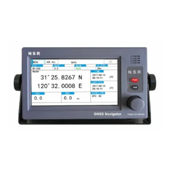
Page 13: Nav Data Display
The Nav data display shows position in latitude and longitude, course, speed, date and time. The NGR-3000 takes about 120 seconds to find position when turned on for the very first time. Thereafter it takes about 15 seconds to find position each time the power is turned on. -
Page 14: Compass Display
MAIN menu. Please refer to complete MENU TREE in the Appendix. 1) Click the [MENU] to display the menu. 2) Turn the knob and press the knob to confirm the selection or click directly to select an item on screen. NGR-3000 OM E. 20170815-02... -
Page 15: H Ow To Enter Character Data
2) Click RENAME to rename the route desired. 3) Click the character among A-Z desired. Turn the knob to select an item on screen and press the knob to confirm the selection. 4) Click the [√] to finish. NGR-3000 OM E. 20170815-02... -
Page 16: Plotter Display Overview
1) Click the [OPERATE] key. The pop-up menu appears. 2) Click “ZOOM IN” or “ZOOM OUT” to select range desired. 3) Click on any blank space to finish. 3.2 Stop the navigation by the current route NGR-3000 OM E. 20170815-02... -
Page 17: A Dd A New Waypoint To The Route
The sequence of waypoints leading to the ultimate destination is called a route. The NGR-3000 can automatically advance to the next waypoint on a route, so you do not have to change the destination waypoint repeatedly. The NGR-3000 can store 30 routes and each route may include up to 30 waypoints. -
Page 18: R Egistering Waypoints
NGR-3000 USER’S MANUAL (2) Click PLOTTER in MENU, then click WAYPOINT/ROUTE in OPERATE to open the menu. 4.1 Registering waypoints Click NAVIGATION in SETTINGS to open the list. NGR-3000 OM E. 20170815-02... -
Page 19: Insert A New Waypoint
Create a new waypoint with the position as own ship’s current position. The new waypoint will be inserted after the waypoint which is selected by the current cursor. 4.1.2 EDIT a waypoint Edit the selected waypoint. NGR-3000 OM E. 20170815-02... -
Page 20: Delete A Waypoint
4) Turn the knob to select “latitude”, “longitude”. 5) Click the [√] key to finish the waypoint. 4.1.3 DELETE a waypoint Delete the selected waypoint. 4.2 Route Planning NGR-3000 OM E. 20170815-02... -
Page 21: Edit A Route
Click the “ADD” to display the waypoints registered. The screen will return to the route and a new waypoint has been added just after the current waypoint. EDIT a waypoint Edit a waypoint in the route. Click the “EDIT” to edit the waypoint. NGR-3000 OM E. 20170815-02... -
Page 22: Navigation By The Route Forward
3) Click the [√] to finish. DELETE a waypoint Click the “DELETE” to delete the selected waypoint from the route. 4.2.2 Navigation by the Route Forward Click the “FORWARD” in MENU to start navigation forward. The plotter screen is displayed. NGR-3000 OM E. 20170815-02... -
Page 23: Navigation By The Route Reverse
NGR-3000 USER’S MANUAL 4.2.3 Navigation by the Route Reverse Click the “REVERSE” to start navigation reversely. The plotter screen is displayed. NGR-3000 OM E. 20170815-02... -
Page 24: Stop Navigation
Click the “STOP” to stop navigation and no navigation data is listed on Plotter display. 4.2.5 Create a new route Click the “ADD” to add a new route just after the current route. 4.2.6 Delete a route Click the “DELETE” to delete the selected route from route list. NGR-3000 OM E. 20170815-02... -
Page 25: Navigation Setting
5. NAVIGATION SETTING Select NAVIGATION SETTING in WAYPOINT/ROUTE to open the menu. 5.1 Setup XTE (Cross Track Error) Alarm The XTE alarm warns by an internal buzzer you when own ship is off its intended route. NGR-3000 OM E. 20170815-02... - Page 26 HIGH: Alarm is activated when speed is higher than the speed set. 3) Click the SPEED value to edit. 4) Click the digits among 0-9 until the desired digit is got. 5) Turn the knob to move the cursor to the next digit to edit. NGR-3000 OM E. 20170815-02...
-
Page 27: Anchor Watch Alarm
4) Turn the knob to move the cursor to the next digit to edit. The alarm range is (0.01-99.99 nm). Anchor watch alarm The anchor watch alarm sounds to warn you that own ship is moving beyond the set area. NGR-3000 OM E. 20170815-02... - Page 28 ANC. The anchor watch starts. 5.4 Set up the Track record TRACK is to set the interval of every two recorded dots. NGR-3000 OM E. 20170815-02...
- Page 29 If DISTANCE is selected, the track will be recorded every certain distance which can be configured. If AUTO is selected, the track will be recorded every minute or every certain distance which can be configured, whichever is reached first. NGR-3000 OM E. 20170815-02...
-
Page 30: Maintenance & Diagnostics
Speed alarm setting violated. XTE! XTE alarm setting violated. OUTPUT ERROR! Too many sentences selected. The alarm parameters are set in NAVIGATION SETTING. 6.3 Diagnostic Test The diagnostic test checks software version, keyboard and LCD for proper operation. NGR-3000 OM E. 20170815-02... -
Page 31: Software Version
NGR-3000 USER’S MANUAL 6.3.1 Software version Select SOFTWARE VERSION item and press the [ENT] key to check the software version. NGR-3000 OM E. 20170815-02... -
Page 32: Gnss Monitoring
Press DIM to test the Display Brightness. 6.3.5 Erase navigation data 6.3.6 Factory default FACTORY DEFAULT is to return the system to factory default setting. Select FACTORY DEFAULT item in DIAGNOSTICS menu. Press the [ENT] key to restore the factory default settings. NGR-3000 OM E. 20170815-02... - Page 33 NGR-3000 USER’S MANUAL NOTE: The navigation settings and GPS settings will restore to factory default while the waypoints and routes registered remain unchanged. NGR-3000 OM E. 20170815-02...
-
Page 34: Menu Operation
[MENU] and press the knob to determine the entry. 3) Click the [ ] to return to previous menu. 7.2 GNSS SETTING 7.2.1 GEODETIC DATUM Totally there are two systems to be selected among: WGS84, PZ-90. NGR-3000 OM E. 20170815-02... -
Page 35: Raim
The "unsafe" state can be reached when satellite range errors degrade the navigation solution, causing the resulting accuracy to be outside the selected accuracy level. 7.2.3 ACCURACY LEVEL Accuracy level can be set between 10-100m. NGR-3000 OM E. 20170815-02... -
Page 36: Rtcm
NGR-3000 USER’S MANUAL 7.2.4 RTCM RTCM can be set ON or OFF. When set ON, DGPS beacon input will be checked by NGR-3000. 7.3 SYSTEM SETTING 7.3.1 KEY BUZZER Buzzer can be muted so that operation is not heard. 7.3.2 LCD/KEY DIMMER Dimmer can be adjusted either by DIM button or set in menu. -
Page 37: Installation
GPS satellite signal if the water freezes. • If the antenna cable is to be passed through a hole which is not large enough to pass the connector, you may unfasten the connector. Refasten it after running the cable through the hole. NGR-3000 OM E. 20170815-02... -
Page 38: Cabling
8.4 INITIAL SETTINGS This equipment can output navigation data to external equipment, in NMEA 0183 format. For example, it can output position data to a radar or echo sounder for display on its display screen. 8.4.1 SENTENCE SETTING NGR-3000 OM E. 20170815-02... - Page 39 OVERFLOW will be indicated in the relative column. In this case, OUTPUT ERROR will also be shown in displayed screens. Move the cursor to the item and click it to select it or deselect a sentence. NGR-3000 OM E. 20170815-02...
- Page 40 DTM: Datum reference. GSA: GNSS receiver operating mode, satellites used in the navigation solution reported by the GGA 2148 or GNS sentences, and DOP values. NOTE: As default, GNS, GBS, GGA, RMC, ZDA and DTM are selected. NGR-3000 OM E. 20170815-02...
-
Page 41: Baud Rate Setting
Move the cursor to the output and click it continuously until a desired rate is shown. 1、The baud rate can be selected among 4800/ 9600/ 19200/ 38400bps. 2、The NMEA Version can be selected among 1.5/ 2.0/ 2.3/IEC61162 Ed4/IEC61162 Ed5. NGR-3000 OM E. 20170815-02... -
Page 42: Appedix I Menu Tree
NGR-3000 USER’S MANUAL APPEDIX I MENU TREE NGR-3000 OM E. 20170815-02... - Page 43 Display Unit: -15° C to +55° C (2) Relative Humidity 95% at 40° C (3) Water Proofing Antenna Unit: IEC60529 IPX6 Display Unit: IEC60529 IPX5 6. OTHERS (1) Size 145(H) x 264(W) x 80(D) mm (2) Weight abt 2 kg (main unit) NGR-3000 OM E. 20170815-02...
-
Page 44: Appedix Iii Sentence Discription
NGR-3000 USER’S MANUAL APPEDIX III SENTENCE DISCRIPTION NGR-3000 OM E. 20170815-02... - Page 45 : request / repeat information : responsibility transfer: silence : NOTE 6: This field should be “C” and should not be null field. This field indicates a command. A sentence without “C” is not a command. NGR-3000 OM E. 20170815-02...
- Page 46 • Alert instance (see ALF Alert instance) • Revision Counter (see ALF Revision Counter) Each entry identifies a certain alert with a certain state. It is not allowed that an alert entry is split between two ALC sentences. NGR-3000 OM E. 20170815-02...
- Page 47 It should by either a null field (if not used) or UTC (if used). Sender is allowed to use all alternatives defined in Table 5 Field type summary. Receiver is allowed to ignore content of this field. If the receiver NGR-3000 OM E. 20170815-02...
- Page 48 (alert identifier). It is not permitted to modify the alert instance within a life cycle of a distributed alert (from ‘active & unacknowledged’ state until ‘normal’ state is reached). It can be also a null field, when there is only one alert of that type. NGR-3000 OM E. 20170815-02...
- Page 49 NOTE 12: This field is used for Alert title which is mandatory and for additional alert description which is optional. NGR-3000 OM E. 20170815-02...
- Page 50 2. Local datum subdivision code 3. Lat offset, min, N/S 4. Lon offset, min, E/W 5. Altitude offset, m 6. Reference datum W84 - WGS84 W72 - WGS72 S85 - SGS85 P90 - PE90 7. Checksum NGR-3000 OM E. 20170815-02...
- Page 51 Expected error in altitude ID number (see Note 2) of most likely failed satellite Probability of missed detection for most likely failed satellite Estimate of bias on most likely failed satellite 8.Standard deviation of bias estimate NGR-3000 OM E. 20170815-02...
- Page 52 $-- GNS, hhmmss.ss, llll.ll, a, yyyyy.yy, a, c--c,xx,x.x,x.x,x.x,x.x,x.x,a *hh<CR><LF> +--------- 6 +---------- 5 +------------- 4 +----------+------------- 3 +-- +-------------------- 2 +---------------------------- 1 UTC of position 2. Latitude, N/S Longitude, E/W Mode indicator Total number of satellites in use, 00-99 HDOP NGR-3000 OM E. 20170815-02...
- Page 53 5. Number of satellite in use,00-12, may be different from the number in view 6. Horizontal dilution of precision 7. Antenna altitude above/below mean sea level, m 8. Geoidal separation, m 9. Age of differential GPS data 10. Differential reference station ID, 0000-1023 11. Checksum NGR-3000 OM E. 20170815-02...
- Page 54 GLONASS constellation of 24 satellites, thus giving a range of 65 through 88. The numbers 89 through 96 are available if slot numbers above 24 are allocated to on- orbit spares. NOTE 2: GNSS System ID identifies the GNSS System ID according to the Table below. NGR-3000 OM E. 20170815-02...
- Page 55 NOTE 3: The sequential sentence identifier provides a message identification number from 0 to 9 that is sequentially assigned and is incremented for each new sentence. The count resets to 0 after 9 is used. NGR-3000 OM E. 20170815-02...
- Page 56 The status field should be set to V = Invalid for all values of the mode indicator except for A= Autonomous, D = Differential, F = Float RTK, P = Precise and R = Real time kinematic. The positioning system mode indicator and status fields should not be null fields. NGR-3000 OM E. 20170815-02...
- Page 57 1 s for a conventional craft and 0,5 s for a high speed craft. V = Navigational status not valid, equipment is not providing navigational status indication. NGR-3000 OM E. 20170815-02...
- Page 58 5. Mode indicator(see note) 6. Checksum NOTE Positioning system Mode indicator: A = Autonomous D = Differential S = Simulator N = Data not valid The positioning system Mode indicator field shall not be a null field. NGR-3000 OM E. 20170815-02...
- Page 59 1. UTC 2. Day, 01 to 31 (UTC) 3. Month, 01 to 12 (UTC) 4. Year (UTC) 5. Local zone hours, 00h to +-13h 6. Local zone minutes, 00 to +59 as local hours 7. Checksum NGR-3000 OM E. 20170815-02...
-
Page 60: Appedix Iv Installation Drawings
NGR-3000 USER’S MANUAL APPEDIX IV INSTALLATION DRAWINGS NGR-3000 OM E. 20170815-02...
Need help?
Do you have a question about the NGR-3000 and is the answer not in the manual?
Questions and answers