Table of Contents
Advertisement
Available languages
Available languages
Version 1.0
Published March 2016
Copyright©2016 ASRock INC. All rights reserved.
Copyright Notice:
No part of this documentation may be reproduced, transcribed, transmitted, or
translated in any language, in any form or by any means, except duplication of
documentation by the purchaser for backup purpose, without written consent of
ASRock Inc.
Products and corporate names appearing in this documentation may or may not
be registered trademarks or copyrights of their respective companies, and are used
only for identification or explanation and to the owners' benefit, without intent to
infringe.
Disclaimer:
Specifications and information contained in this documentation are furnished for
informational use only and subject to change without notice, and should not be
constructed as a commitment by ASRock. ASRock assumes no responsibility for
any errors or omissions that may appear in this documentation.
With respect to the contents of this documentation, ASRock does not provide
warranty of any kind, either expressed or implied, including but not limited to
the implied warranties or conditions of merchantability or fitness for a particular
purpose.
In no event shall ASRock, its directors, officers, employees, or agents be liable for
any indirect, special, incidental, or consequential damages (including damages for
loss of profits, loss of business, loss of data, interruption of business and the like),
even if ASRock has been advised of the possibility of such damages arising from any
defect or error in the documentation or product.
This device complies with Part 15 of the FCC Rules. Operation is subject to the following
two conditions:
(1) this device may not cause harmful interference, and
(2) this device must accept any interference received, including interference that
may cause undesired operation.
CALIFORNIA, USA ONLY
The Lithium battery adopted on this motherboard contains Perchlorate, a toxic substance
controlled in Perchlorate Best Management Practices (BMP) regulations passed by the
California Legislature. When you discard the Lithium battery in California, USA, please
follow the related regulations in advance.
"Perchlorate Material-special handling may apply, see www.dtsc.ca.gov/hazardouswaste/
perchlorate"
ASRock Website: http://www.asrock.com
Advertisement
Table of Contents

Related Manuals for ASROCK Fatal1ty H170


Summary of Contents for ASROCK Fatal1ty H170
-
Page 1: Copyright Notice
(including damages for loss of profits, loss of business, loss of data, interruption of business and the like), even if ASRock has been advised of the possibility of such damages arising from any defect or error in the documentation or product. - Page 2 If you require assistance please call ASRock Tel : +886-2-28965588 ext.123 (Standard International call charges apply) The terms HDMI™...
- Page 3 Fatal1ty Story Who knew that at age 19, I would be a World Champion PC gamer. When I was 13, I actually played competitive billiards in professional tournaments and won four or five games off guys who played at the highest level. I actually thought of making a career of it, but at that young age situations change rapidly.
- Page 4 LIVIN’ LARGE Since my first big tournament wins, I have been a “Professional Cyberathlete”, traveling the world and livin’ large with lots of International media coverage on outlets such as MTV, ESPN and a 60 Minutes segment on CBS to name only a few. It's unreal - it's crazy. I’m living a dream by playing video games for a living.
-
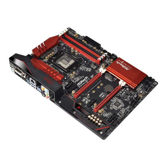
Page 5: Motherboard Layout
Fatal1ty H170 Performance/Hyper Series Motherboard Layout CPU_FAN1 ATX12V1 USB 3.0 Top: T: USB3 RJ-45 B: USB4 USB 3.0 T: USB5 B: USB6 CHA_FAN4 PCIE_PWR1 CPU_FAN2 PCIE1 H170 Performance/Hyper PCIE2 Intel CMOS PCIE3 Battery H170 PCIE4 Purity RoHS Sound 3 BIOS_A1... - Page 6 No. Description ATX 12V Power Connector (ATX12V1) 2 x 288-pin DDR4 DIMM Slots (DDR4_A1, DDR4_B1) 2 x 288-pin DDR4 DIMM Slots (DDR4_A2, DDR4_B2) CPU Fan Connector (CPU_FAN1) ATX Power Connector (ATXPWR1) Chassis Fan Connector (CHA_FAN4) USB 3.0 Header (USB3_7_8) SATA3 Connectors (SATA3_0_1) CPU Fan Connector (CPU_FAN2) SATA3 Connectors (SATA3_3_5) SATA3 Connectors (SATA3_2_4)
- Page 7 Fatal1ty H170 Performance/Hyper Series 1.4 I/O Panel No. Description No. Description Fatal1ty Mouse Port (USB1) Front Speaker (Lime)** USB 2.0 Port (USB2) Microphone (Pink) DVI-D Port Optical SPDIF Out Port USB 3.0 Port (USB3_1) USB 3.0 Ports (USB3_56) LAN RJ-45 Port* USB 3.0 Ports (USB3_34)
- Page 8 * There are two LEDs on each LAN port. Please refer to the table below for the LAN port LED indications. ACT/LINK LED SPEED LED LAN Port Activity / Link LED Speed LED Status Description Status Description No Link 10Mbps connection Blinking Data Activity Orange...
-
Page 9: Chapter 1 Introduction
If you require technical support related to this mother- board, please visit our website for specific information about the model you are using. You may find the latest VGA cards and CPU support list on ASRock’s website as well. ASRock website http://www.asrock.com. -
Page 10: Specifications
• Supports DDR4 2133 non-ECC, un-buffered memory • Supports ECC UDIMM memory modules (operate in non- ECC mode) * Please refer to Memory Support List on ASRock's website for more information. (http://www.asrock.com/) • Max. capacity of system memory: 64GB • Supports Intel® Extreme Memory Profile (XMP) 2.0 • 15μ... - Page 11 • 7.1 CH HD Audio with Content Protection (Realtek ALC1150 Audio Codec) • Premium Blu-ray Audio support • Supports Surge Protection (ASRock Full Spike Protection) • Supports Purity Sound - Nichicon Fine Gold Series Audio Caps - 115dB SNR DAC with Differential Amplifier - TI®...
- Page 12 • 1 x DVI-D Port • 1 x HDMI Port • 1 x Optical SPDIF Out Port • 1 x USB 2.0 Port (Supports ESD Protection (ASRock Full Spike Protection)) • 1 x Fatal1ty Mouse Port (USB 2.0) (Supports ESD Protection (ASRock Full Spike Protection)) • 5 x USB 3.0 Type-A Ports (Supports ESD Protection (ASRock...
- Page 13 • 1 x Front Panel Audio Connector • 2 x USB 2.0 Headers (Support 4 USB 2.0 ports) (Supports ESD Protection (ASRock Full Spike Protection)) • 1 x USB 3.0 Header (Supports 2 USB 3.0 ports) (Supports ESD Protection (ASRock Full Spike Protection)) BIOS • 2 x AMI UEFI Legal BIOS with multilingual GUI support (1...
- Page 14 * For the updated Windows® 10 driver, please visit ASRock’s website for details: http://www.asrock.com. Certifica- • FCC, CE, WHQL tions • ErP/EuP ready (ErP/EuP ready power supply is required) * For detailed product information, please visit our website: http://www.asrock.com Please realize that there is a certain risk involved with overclocking, including adjusting the setting in the BIOS, applying Untied Overclocking Technology, or using third-party overclocking tools.
-
Page 15: Chapter 2 Installation
Fatal1ty H170 Performance/Hyper Series Chapter 2 Installation This is an ATX form factor motherboard. Before you install the motherboard, study the configuration of your chassis to ensure that the motherboard fits into it. Pre-installation Precautions Take note of the following precautions before you install motherboard components or change any motherboard settings. -
Page 16: Installing The Cpu
2.1 Installing the CPU 1. Before you insert the 1151-Pin CPU into the socket, please check if the PnP cap is on the socket, if the CPU surface is unclean, or if there are any bent pins in the socket. Do not force to insert the CPU into the socket if above situation is found. - Page 17 Fatal1ty H170 Performance/Hyper Series...
- Page 18 Please save and replace the cover if the processor is removed. The cover must be placed if you wish to return the motherboard for after service.
- Page 19 Fatal1ty H170 Performance/Hyper Series 2.2 Installing the CPU Fan and Heatsink...
-
Page 20: Dual Channel Memory Configuration
2.3 Installing Memory Modules (DIMM) This motherboard provides four 288-pin DDR4 (Double Data Rate 4) DIMM slots, and supports Dual Channel Memory Technology. 1. For dual channel configuration, you always need to install identical (the same brand, speed, size and chip-type) DDR4 DIMM pairs. 2. - Page 21 Fatal1ty H170 Performance/Hyper Series...
- Page 22 2.4 Expansion Slots (PCI Express Slots) There are 5 PCI Express slots on the motherboard. Before installing an expansion card, please make sure that the power supply is switched off or the power cord is unplugged. Please read the documentation of the expansion card and make necessary hardware settings for the card before you start the installation.
-
Page 23: Jumpers Setup
Fatal1ty H170 Performance/Hyper Series 2.5 Jumpers Setup The illustration shows how jumpers are setup. When the jumper cap is placed on the pins, the jumper is “Short”. If no jumper cap is placed on the pins, the jumper is “Open”. The illustration shows a 3-pin jumper whose pin1 and pin2 are “Short”... - Page 24 BIOS Selection Jumper (BIOS_SEL1) Default Backup BIOS (see p.1, No. 20) (Main BIOS) This motherboard has two BIOS onboard, a main BIOS (BIOS_A1) and a backup BIOS (BIOS_B1), which enhances protection for the safety and stability of your system. Normally, the system works on the main BIOS. However, if the main BIOS is corrupted or damaged, please use a jumper cap to short pin2 and pin3, then the backup BIOS will take over on the next system boot.
-
Page 25: Onboard Headers And Connectors
Fatal1ty H170 Performance/Hyper Series 2.6 Onboard Headers and Connectors Onboard headers and connectors are NOT jumpers. Do NOT place jumper caps over these headers and connectors. Placing jumper caps over the headers and connectors will cause permanent damage to the motherboard. - Page 26 Power LED and Speaker Please connect the SPEAKER DUMMY Header chassis power LED and DUMMY (7-pin SPK_PLED1) the chassis speaker to this (see p.1, No. 17) header. PLED+ PLED+ PLED- Serial ATA3 Connectors These six SATA3 (SATA3_0_1: connectors support SATA see p.1, No.
- Page 27 Fatal1ty H170 Performance/Hyper Series USB 3.0 Header Besides six USB 3.0 ports Vbus Vbus (19-pin USB3_7_8) on the I/O panel, there Vbus IntA_PB_SSRX- IntA_PA_SSRX- IntA_PB_SSRX+ (see p.1, No. 7) is one header on this IntA_PA_SSRX+ motherboard. Each USB IntA_PB_SSTX- IntA_PA_SSTX- IntA_PB_SSTX+ 3.0 header can support...
- Page 28 Chassis Fan Connectors Please connect fan cables (4-pin CHA_FAN1) to the fan connectors and (see p.1, No. 13) match the black wire to FAN_VOLTAGE FAN_SPEED (4-pin CHA_FAN2) the ground pin. FAN_SPEED_CONTROL (see p.1, No. 12) (4-pin CHA_FAN3) (see p.1, No. 21) (4-pin CHA_FAN4) FAN_SPEED_CONTROL FAN_SPEED...
- Page 29 Fatal1ty H170 Performance/Hyper Series Serial Port Header This COM1 header RRXD1 DDTR#1 (9-pin COM1) supports a serial port DDSR#1 CCTS#1 (see p.1, No. 23) module. RRI#1 RRTS#1 TTXD1 DDCD#1 TPM Header This connector supports Trusted (17-pin TPMS1) Platform Module (TPM) system, (see p.1, No.
- Page 30 2.7 M.2_SSD (NGFF) Module Installation Guide The M.2, also known as the Next Generation Form Factor (NGFF), is a small size and versatile card edge connector that aims to replace mPCIe and mSATA. The Ultra M.2 Socket (M2_1), supports M.2 PCI Express module up to Gen3 x4 (32 Gb/s). *If M2_1 is occupied by a SATA-type M.2 device, SATA3_0 and the SATA function of SATA3_2_3 will be disabled.
- Page 31 Fatal1ty H170 Performance/Hyper Series Step 3 Move the standoff based on the module type and length. The standoff is placed at the nut location D by default. Skip Step 3 and 4 and go straight to Step 5 if you are going to use the default nut.
- Page 32 SATA3 2280 TM8PS4256GMC105 Team 256GB SATA3 2242 TM4PS4256GMC105 Transcend 256GB SATA3 2242 TS256GMTS400 Transcend 512GB SATA3 2280 TS512GMTS800 Transcend 512GB SATA3 2260 TS512GMTS600 For the latest updates of M.2_SSD (NFGG) module support list, please visit our website for details: http://www.asrock.com...
- Page 33 Fatal1ty H170 Performance/Hyper Series 1 Einleitung Vielen Dank, dass Sie sich für die ASRock Fatal1ty H170 Performance/Hyper Series entschieden haben – ein zuverlässiges Motherboard, das konsequent unter der strengen Qualitätskontrolle von ASRock hergestellt wurde. Es liefert ausgezeichnete Leistung mit robustem Design, das ASRocks Streben nach Qualität und Beständigkeit erfüllt.
-
Page 34: Technische Daten
Prozessor Celeron® der 6. Generation (Sockel 1151) • Digipower-Design • 10-Leistungsphasendesign • Unterstützt Intel® Turbo Boost 2.0-Technologie • Unterstützt ASRock BCLK-Übertaktung (voller Bereich) • Unterstützt ASRock-Hyper-BCLK-Engine Chipsatz • Intel® H170 • Unterstützt Intel® Small Business Advantage 4.0 Speicher • Dualkanal-DDR4-Speichertechnologie • 4 x DDR4-DIMM-Steckplätze... - Page 35 DVI-D- und HDMI-Ports Audio • 7.1-Kanal-HD-Audio mit Inhaltsschutz (Realtek ALC1150- Audiocodec) • Erstklassige Blu-ray-Audiounterstützung • Unterstützt Überspannungsschutz (ASRock Full Spike Protection) • Unterstützt Purity Sound - Nichicon-Audiokappen der Fine Gold-Serie - 115-dB-SRV-DAC mit Differentialverstärker - TI® NE5532 – erstklassiger Headset-Verstärker (unterstützt...
- Page 36 • 1 x USB 2.0-Port (unterstützt Schutz gegen elektrostatische Entladung (ASRock Full Spike Protection)) • 1 x Fatal1ty-Mausport (USB 2.0) (unterstützt Schutz gegen elektrostatische Entladung (ASRock Full Spike Protection)) • 5 x USB 3.0-Typ-A-Ports (unterstützt Schutz gegen elektrostatische Entladung (ASRock Full Spike Protection)) • 1 x USB 3.0-Typ-C-Port (unterstützt Schutz gegen...
- Page 37 ISO-Datei benötigt. Detaillierte Anweisungen finden Sie auf Seite 175. * Einzelheiten zum aktualisierten Windows® 10-Treiber entnehmen Sie bitte der ASRock-Webseite: http://www. asrock.com. Zertifizierun- • FCC, CE, WHQL • ErP/EuP ready (ErP/EuP ready-Netzteil erforderlich) * Detaillierte Produktinformationen finden Sie auf unserer Webseite: http://www.asrock.com...
- Page 38 Bitte beachten Sie, dass mit einer Übertaktung, zu der die Anpassung von BIOS-Einstellungen, die Anwendung der Untied Overclocking Technology oder die Nutzung von Übertaktung- swerkzeugen von Drittanbietern zählen, bestimmte Risiken verbunden sind. Eine Übertaktung kann sich auf die Stabilität Ihres Systems auswirken und sogar Komponenten und Geräte Ihres Systems beschädigen.
- Page 39 Fatal1ty H170 Performance/Hyper Series 1.3 Jumpereinstellung Die Abbildung zeigt, wie die Jumper eingestellt werden. Wenn die Jumper-Kappe auf den Kontakten angebracht ist, ist der Jumper „kurzgeschlossen“. Wenn keine Jumper- Kappe auf den Kontakten angebracht ist, ist der Jumper „offen“. Die Abbildung zeigt einen 3-poligen Jumper, dessen Kontakt 1 und Kontakt 2 „kurzgeschlossen“...
- Page 40 BIOS-Auswahl-Jumper (BIOS_SEL1) Standard Ausfall-BIOS (siehe S. 1, Nr. 20) (Haupt-BIOS) Dieses Motherboard verfügt über zwei integrierte BIOS, ein Haupt-BIOS (BIOS_A1) und ein Ausfall-BIOS (BIOS_B1), die den Schutz in puncto Sicherheit und Stabilität Ihres Systems steigern. Normalerweise läuft das System über das Haupt-BIOS. Falls das Haupt-BIOS jedoch defekt oder beschädigt ist, schließen Sie bitte Kontakt 2 und Kontakt 3 über eine Jumperkappe kurz;...
- Page 41 Fatal1ty H170 Performance/Hyper Series 1.4 Integrierte Stiftleisten und Anschlüsse Integrierte Stiftleisten und Anschlüsse sind KEINE Jumper. Bringen Sie KEINE Jumper-Kappen an diesen Stiftleisten und Anschlüssen an. Durch Anbringen von Jumper-Kappen an diesen Stiftleisten und Anschlüssen können Sie das Motherboard dauerhaft beschädigen.
- Page 42 Betrieb-LED- und Bitte verbinden Sie SPEAKER DUMMY Lautsprecher-Stiftleiste die Betrieb-LED des DUMMY (7-polig, SPK_PLED1) Gehäuses und den (siehe S. 1, Nr. 17) Gehäuselautsprecher mit dieser Stiftleiste. PLED+ PLED+ PLED- Serial-ATA-III-Anschlüsse Diese sechs SATA-III- (SATA3_0_1: Anschlüsse unterstützen siehe S. 1, Nr. 8) SATA-Datenkabel für (SATA3_2_4: interne Speichergeräte mit...
- Page 43 Fatal1ty H170 Performance/Hyper Series USB 3,0-Stiftleiste Neben sechs USB 3.0-Ports Vbus Vbus (19-polig, USB3_7_8) an der E/A-Blende befindet Vbus IntA_PB_SSRX- IntA_PA_SSRX- IntA_PB_SSRX+ (siehe S. 1, Nr. 7) sich eine Stiftleiste an IntA_PA_SSRX+ diesem Motherboard. Jede IntA_PB_SSTX- IntA_PA_SSTX- IntA_PB_SSTX+ USB 3.0-Stiftleiste kann...
- Page 44 Gehäuselüfteranschlüsse Bitte verbinden Sie die (4-polig, CHA_FAN1) Lüfterkabel mit den (siehe S. 1, Nr. 13) Lüfteranschlüssen; der FAN_VOLTAGE FAN_SPEED (4-polig, CHA_FAN2) schwarze Draht gehört FAN_SPEED_CONTROL (siehe S. 1, Nr. 12) zum Erdungskontakt. (4-polig, CHA_FAN3) (siehe S. 1, Nr. 21) (4-polig, CHA_FAN4) FAN_SPEED_CONTROL FAN_SPEED (siehe S.
- Page 45 Fatal1ty H170 Performance/Hyper Series Serieller-Port-Stiftleiste Diese COM1-Stiftleiste RRXD1 DDTR#1 (9-polig, COM1) unterstützt ein Modul für DDSR#1 CCTS#1 (siehe S. 1, Nr. 23) serielle Ports. RRI#1 RRTS#1 TTXD1 DDCD#1 TPM-Stiftleiste Dieser Anschluss unterstützt das (17-polig, TPMS1) Trusted Platform Module- (TPM) (siehe S. 1, Nr. 22) System, das Schlüssel, digitale...
- Page 46 à modification sans préavis. En cas de modifications du présent document, la version mise à jour sera disponible sur le site Internet ASRock sans notification préalable. Si vous avez besoin d’une assistance technique pour votre carte mère, veuillez visiter notre site Internet pour plus de détails sur le modèle que vous utilisez.
- Page 47 • Conception Digi Power • Alimentation à 10 phases • Prend en charge la technologie Intel® Turbo Boost 2.0 • Prend en charge l’ o verclocking ASRock BCLK Full-range • Prend en charge le moteur ASRock Hyper BCLK Chipset • Intel® H170 • Prend en charge Intel®...
- Page 48 - Blindage isolant PCB • Prend en charge DTS Connect Réseau • Gigabit LAN 10/100/1000 Mb/s • Giga PHY Intel® I219V • Prend en charge la fonction Wake-On-LAN • Protection contre les orages/décharges électrostatiques (Protection complète contre les pics ASRock)
- Page 49 6,0 Gb/s type 2230/2242/2260/2280/22110 et M.2 PCI Express jusqu’à Gen3 x4 (32 Gb/s)** ** Prend en charge les SSD NVMe comme disques de démarrage ** Prend en charge le kit ASRock U.2 Connecteur • 1 x embase pour port COM • 1 x embase TPM...
- Page 50 ISO est requis. Reportez-vous à la page 175 pour des instructions plus détaillées. * Pour le pilote mis à jour pour Windows® 10, veuillez visiter le site Web d’ A SRock pour plus de détails : http://www.asrock.com.
- Page 51 • FCC, CE, WHQL • ErP/EuP Ready (alimentation ErP/EuP ready requise) * pour des informations détaillées de nos produits, veuillez visiter notre site : http://www.asrock.com Il est important de signaler que l’ o vercloking présente certains risques, incluant des modifications du BIOS, l’ a pplication d’une technologie d’ o verclocking déliée et l’utilisation d’ o utils d’...
- Page 52 1.3 Configuration des cavaliers (jumpers) L’illustration ci-dessous vous renseigne sur la configuration des cavaliers (jumpers). Lorsque le capuchon du cavalier est installé sur les broches, le cavalier est « court- circuité ». Si le capuchon du cavalier n’ e st pas installé sur les broches, le cavalier est « ouvert ».
- Page 53 Fatal1ty H170 Performance/Hyper Series Sélection du cavalier du BIOS Par défaut BIOS de secours (BIOS_SEL1) (BIOS principal) (voir p.1, No. 20) Cette carte mère est dotée de deux BIOS – un BIOS principal (BIOS_A1), et un BIOS de secours (BIOS_B1) – ce qui permet d’ o ptimiser la protection du système pour des performances fiables et stables.
- Page 54 1.4 Embases et connecteurs de la carte mère Les embases et connecteurs situés sur la carte NE SONT PAS des cavaliers. Ne placez JAMAIS de capuchons de cavaliers sur ces embases ou connecteurs. Placer un capuchon de cavalier sur ces embases ou connecteurs endommagera irrémédiablement votre carte mère. Embase du panneau Branchez le bouton de PLED+...
- Page 55 Fatal1ty H170 Performance/Hyper Series Prise DEL d’alimentation Veuillez brancher la DEL SPEAKER DUMMY et haut-parleur d'alimentation du châssis DUMMY (SPK_PLED1 à 7 broches) et le haut-parleur du (voir p.1, No. 17) châssis sur ce connecteur. PLED+ PLED+ PLED- Connecteurs Serial ATA3...
- Page 56 Embases USB 2.0 Cette carte mère comprend USB_PWR (USB1_2 9 broches deux connecteurs. Chaque (voir p.1, No. 18) DUMMY embase USB 2,0 peut (USB3_4 à 9 broches) prendre en charge deux (voir p.1, No. 19) ports. USB_PWR Embases USB 3.0 En plus des six ports Vbus Vbus (USB3_7_8 19 broches)
- Page 57 Fatal1ty H170 Performance/Hyper Series Connecteurs du Veuillez brancher les câbles ventilateur du châssis du ventilateur sur les (CHA_FAN1 à 4 broches) connecteurs du ventilateur, FAN_VOLTAGE FAN_SPEED (voir p.1, No. 13) puis reliez le fil noir à la FAN_SPEED_CONTROL (CHA_FAN2 à 4 broches) broche de mise à...
- Page 58 Embase pour port série Cette embase COM1 prend RRXD1 DDTR#1 (COM1 à 9 broches) en charge un module de DDSR#1 CCTS#1 (voir p.1, No. 23) port série. RRI#1 RRTS#1 TTXD1 DDCD#1 Embase TPM Ce connecteur prend en charge un (TPMS1 à 17 broches) module TPM (Trusted Platform (voir p.1, No.
- Page 59 Web di ASRock senza ulteriore preavviso. Per il supporto tecnico correlato a questa scheda madre, visitare il nostro sito Web per informazioni specifiche relative al modello attualmente in uso.
- Page 60 • Design Digi Power • Potenza a 10 fasi • Supporta la tecnologia Intel® Turbo Boost 2.0 • Supporto di CPU unlocked Intel® K-Series • Supporta gamma completa overclocking BCLK ASRock Chipset • Intel® H170 • Supporta Intel® Small Business Advantage 4.0 Memoria • Tecnologia memoria DDR4 Dual Channel...
- Page 61 • Supporta DTS Connect • LAN Gigabit 10/100/1000 Mb/s • Giga PHY Intel® I219V • Supporta Wake-On-LAN • Supporto la protezione da fulmini/scariche elettrostatiche (ESD) (protezione completa ASRock dai picchi di corrente) • Supporta Energy Efficient Ethernet 802.3az • Supporta PXE...
- Page 62 • 1 x porta HDMI • 1 x porta uscita SPDIF ottico • 1 x Porta USB 2.0 (supporto protezione da scariche elettrostatiche (ESD) (protezione completa ASRock dai picchi di corrente)) • 1 x Porta mouse Fatal1ty (USB 2.0) (supporto protezione da...
- Page 63 * Per installare Windows® 7, è necessario un disco di installazione modificato con i driver xHCI integrati nel file ISO. Fare riferi- mento a pagina 175 per altre istruzioni dettagliate. * Per il driver aggiornato di Windows® 10, visitare il sito ASRock all’indirizzo: http://www.asrock.com. • FCC, CE, WHQL Certificazioni • ErP/EuP Ready (è...
- Page 64 Prestare attenzione al potenziale rischio previsto nella pratica di overclocking, inclusa la regolazione delle impostazioni nel BIOS, l'applicazione di tecnologia di Untied Overclocking o l'utilizzo di strumenti di overclocking di terze parti. L'overclocking può influenzare la stabilità del sistema o perfino provocare danni ai componenti e ai dispositivi del sistema. Occorre eseguirlo a proprio rischio e spese.
- Page 65 Fatal1ty H170 Performance/Hyper Series 1.3 Impostazione jumper L'illustrazione mostra in che modo vengono impostati i jumper. Quando il cappuccio del jumper è posizionato sui pin, il jumper è "cortocircuitato". Se sui pin non è posizionato alcun cappuccio del jumper, il jumper è "aperto". L'illustrazione mostra un jumper a 3 pin i cui pin1 e pin2 sono "cortocircuitati"...
- Page 66 Jumper di selezione BIOS (BIOS_SEL1) predefinito BIOS di backup (vedere pag. 1, n. 20) (Main BIOS) Questa scheda madre ha due BIOS su scheda, un BIOS principale (BIOS_A1) e un BIOS di backup (BIOS_B1), che migliorano la protezione e garantiscono la sicurezza e la stabilità...
- Page 67 Fatal1ty H170 Performance/Hyper Series 1.4 Header e connettori sulla scheda Gli header e i connettori sulla scheda NON sono jumper. NON posizionare cappucci del jumper su questi header e connettori. Il posizionamento di cappucci del jumper su header e connettori provocherà...
- Page 68 Connettore LED Collegare i LED SPEAKER DUMMY alimentazione e alimentazione e DUMMY altoparlante l’altoparlante a questo (SPK_PLED1 7 pin) connettore. (vedere pag. 1, n. 17) PLED+ PLED+ PLED- Connettori Serial ATA3 Questi sei connettori (SATA3_0_1: SATA3 supportano cavi vedere pag. 1, n. 8) dati SATA per dispositivi (SATA3_2_4: di archiviazione interna,...
- Page 69 Fatal1ty H170 Performance/Hyper Series Header USB 2.0 Ci sono due connettori USB_PWR (USB1_2 9 pin su questa scheda madre. DUMMY (vedere pag. 1, n. 18) Ciascun header USB 2.0 (9-pin USB3_4) può supportare due porte. (vedere pag. 1, n. 19) USB_PWR Header USB 3.0...
- Page 70 Connettori ventola telaio Collegare i cavi della (CHA_FAN1 a 4 pin) ventola ai connettori della (vedere pag. 1, n. 13) ventola e far corrispondere FAN_VOLTAGE FAN_SPEED (CHA_FAN2 a 4 pin) il filo nero al pin di terra. FAN_SPEED_CONTROL (vedere pag. 1, n. 12) (CHA_FAN3 a 4 pin) (vedere pag.
- Page 71 Fatal1ty H170 Performance/Hyper Series Header porta seriale Questo header COM1 RRXD1 DDTR#1 (COM1 a 9 pin) supporta un modulo di DDSR#1 CCTS#1 (vedere pag. 1, n. 23) porta seriale. RRI#1 RRTS#1 TTXD1 DDCD#1 Header TPM Questo connettore supporta il (TPMS1 a 17 pin) sistema Trusted Platform Module (vedere pag.
-
Page 72: Contenido Del Paquete
Si esta documentación sufre alguna modificación, la versión actualizada estará disponible en el sitio web de ASRock sin previo aviso. Si necesita asistencia técnica relacionada con esta placa base, visite nuestro sitio web para obtener información específica sobre el modelo que esté... - Page 73 • Admite módulos de memoria UDIMM ECC (funcionamiento en modo no ECC) * Para obtener más información, consulte la lista de memorias compatibles en el sitio web de ASRock. (http://www.asrock.com/) • Capacidad máxima de la memoria del sistema: 64GB • Admite Perfil de memoria extremo de Intel® (XMP) 2.0 • Contacto 15μ...
- Page 74 ALC1150 Audio Codec) • Compatible con audio Blu-ray Premium • Compatible con protección por sobretensión (protección ASRock Full Spike) • Compatible con Purity Sound - Tapas de audio Nichion de la serie Fine Gold - 115dB SNR DAC con amplificador diferencial - Amplificador de auriculares de alta calidad TI®...
- Page 75 Full Spike)) • 5 x Puertos USB 3.0 de tipo A (compatible con protección contra electricidad estática (protección ASRock Full Spike)) • 1 x Puerto USB 3.0 de tipo C (compatible con protección contra electricidad estática (protección ASRock Full Spike)) • 1 x puerto LAN RJ-45 con LED (ACT/LINK LED y SPEED...
- Page 76 • 1 Conector de audio del panel frontal • 2 cabezales USB 2.0 (compatible con 4 puertos USB 2.0) (compatible con protección contra electricidad estática (protección ASRock Full Spike)) • 1 cabezal USB 3.0 (compatible con 2 puertos USB 3.0) (compatible con protección contra electricidad estática (protección ASRock Full Spike))
- Page 77 • Compatible con ErP/EuP (requiere toma de alimentación compatible con ErP/EuP) * Para obtener más información acerca del producto, visite nuestro sitio web: http://www.asrock.com Tenga en cuenta que existen ciertos riesgos relacionados con el overclocking (sobreaceleración), incluyendo el ajuste de la configuración del BIOS, aplicando la Tecnología overcloking no vinculada o utilizando las herramientas de overclocking de tercera parte.
- Page 78 1.3 Instalación de los puentes La instalación muestra cómo deben instalarse los puentes. Cuando la tapa de puente se coloca en los pines, el puente queda “Corto”. Si no coloca la tapa de puente en los pines, el puente queda “Abierto”. La ilustración muestra un puente de 3 pines cuyo pin 1 y pin 2 son “Cortos”...
- Page 79 Fatal1ty H170 Performance/Hyper Series Puente de selección del BIOS Predeterminado BIOS de copia (BIOS_SEL1) (BIOS Principal) de seguridad (consulte la pág.1, N.º 20) Esta placa base contiene dos BIOS integrados, un BIOS principal (BIOS_A1) y un BIOS de copia de seguridad (BIOS_B1), que aumentan la protección para la seguridad y la estabilidad de su sistema.
- Page 80 1.4 Conectores y cabezales incorporados Los cabezales y conectores incorporados NO son puentes. NO coloque tapas de puente sobre estos cabezales y conectores. Si coloca tapas de puente sobre los cabezales y conectores dañará de forma permanente la placa base. Cabezal del panel del Conecte el interruptor de PLED+...
- Page 81 Fatal1ty H170 Performance/Hyper Series LED de alimentación y Conecte el LED de SPEAKER DUMMY base de conexiones para la alimentación del chasis y DUMMY altavoz el altavoz del chasis a esta (SPK_PLED1 de 7 base de conexiones. contactos) PLED+ (consulte la pág.1, N.º 17)
- Page 82 Cabezales USB 2.0 Hay dos bases de USB_PWR (USB1_2 de 9 contactos) conexiones en esta placa DUMMY (consulte la pág.1, N.º 18) base. Cada cabezal USB 2.0 (USB3_4 de 9 pines) admite dos puertos. (consulte la pág.1, N.º 19) USB_PWR Cabezal USB 3.0 Además de seis puertos Vbus...
- Page 83 Fatal1ty H170 Performance/Hyper Series Conectores para el Conecte los cables del ventilador del chasis ventilador a los conectores (CHA_FAN1 de 4 pines) del ventilador y haga FAN_VOLTAGE FAN_SPEED (consulte la pág.1, N.º 13) coincidir el cable negro FAN_SPEED_CONTROL (CHA_FAN2 de 4 pines) con el pin de conexión a...
- Page 84 Cabezal de puerto serie Este cabezal COM1 admite RRXD1 DDTR#1 (COM1 de 9 pines) un módulo de puerto serie. DDSR#1 CCTS#1 (consulte la pág.1, N.º 23) RRI#1 RRTS#1 TTXD1 DDCD#1 Cabezal TPM Este conector es compatible con (TPMS1 de 17 pines) el sistema Módulo de Plataforma (consulte la pág.1, N.º...
- Page 85 1.1 Комплект поставки • Системная плата ASRock Fatal1ty H170 Performance/Hyper Series (форм-фактор ATX) • Краткое руководство по установке платы ASRock Fatal1ty H170 Performance/Hyper Series • Компакт-диск с документацией к плате ASRock Fatal1ty H170 Performance/Hyper Series • 2 х кабеля передачи данных Serial ATA (SATA) (приобретаются отдельно) • 1 х...
- Page 86 (Socket 1151) • Digi Power design • Система питания 10 • Поддержка технологии Intel® Turbo Boost 2.0 • Поддержка полного разгона процессора ASRock BCLK • Поддерживает систему ASRock Hyper BCLK Чипсет • Intel® H170 • Поддержка Intel® Small Business Advantage 4.0 Память...
- Page 87 Blu-ray (BD) через порты DVI-D и HDMI Аудио • 7.1-канальный звук высокой четкости HD Audio с защитой данных (аудиокодек Realtek ALC1150) • Поддержка Premium Blu-ray Audio • Защита от перенапряжения (ASRock Full Spike Protection) • Поддержка Purity Sound - Конденсаторы для аудиосистем серии Nichicon Fine Gold...
- Page 88 • Gigabit LAN 10/100/1000 Мб/с • Giga PHY Intel® I219V • Поддержка Wake-On-LAN • Молниезащита и защита электростатического напряжения (ASRock Full Spike Protection) • Поддержка Energy Efficient Ethernet 802.3az • Поддержка PXE • 1 x PS/2 для мыши/клавиатуры Порты ввода- • 1 x DVI-D...
- Page 89 Fatal1ty H170 Performance/Hyper Series Запоминающие • 6 x Разъемы SATA3 со скоростью обмена данными 6,0 ГБ/с, поддержка технологий RAID (RAID 0, RAID устройства 1, RAID 5, RAID 10, Intel Rapid Storage Technology 14 и Intel Smart Response Technology), NCQ, AHCI и...
- Page 90 • FCC, CE, WHQL • Совместимость с ErP/EuP (необходим блок питания, соответствующий стандарту ErP/EuP) * Для получения дополнительной информации об изделии посетите наш веб-сайт: http://www.asrock.com Следует учитывать, что разгон процессора, включая изменение настроек BIOS, применение технологии Untied Overclocking Technology и использование инструментов...
- Page 91 Fatal1ty H170 Performance/Hyper Series 1.3 Установка перемычек Установка перемычек показана на рисунке. При установке колпачковой перемычки на контакты перемычка «замкнута». Если колпачковая перемычка на контакты не установлена, перемычка «разомкнута». На рисунке показана 3-контактная перемычка с замкнутыми контактами 1 и 2 при установке на них...
- Page 92 Перемычка выбора BIOS (BIOS_SEL1) по умолчанию Резервная BIOS (См. стр. 1, № 20) (основная BIOS) Эта системная плата снабжена двумя BIOS (основной BIOS (BIOS_A1) и BIOS резервного копирования (BIOS_B1)), что повышает уровень защиты и стабильность работы системы. Обычно система использует основную BIOS.
- Page 93 Fatal1ty H170 Performance/Hyper Series 1.4 Колодки и разъемы, расположенные на материнской плате Расположенные на материнской плате колодки и разъемы перемычками НЕ являются. НЕ устанавливайте на эти колодки и разъемы колпачковые перемычки. Установка колпачковых перемычек на эти колодки и разъемы может вызвать неустранимое...
- Page 94 Колодка светодиодного Предназначена SPEAKER DUMMY индикатора питания и для подключения DUMMY динамика корпуса светодиодного (7-контактная, SPK_ индикатора питания и PLED1) динамика корпуса. PLED+ (См. стр. 1, № 17) PLED+ PLED- Разъемы Serial ATA3 Эти шесть разъемов (SATA3_0_1: SATA3 предназначены См. стр. 1, № 8) для...
- Page 95 Fatal1ty H170 Performance/Hyper Series Колодки USB 2.0 На системной плате USB_PWR (9-контактная, USB1_2) размещены две колодки. DUMMY (См. стр. 1, № 18) Каждая колодка USB 2.0 (9-контактная USB3_4) может поддерживать два (См. стр. 1, № 19) порта. USB_PWR Колодка USB 3.0 Кроме...
- Page 96 Разъемы вентиляторов Предназначены для корпуса подключения кабелей (4-контактный, CHA_ разъемов вентиляторов FAN_VOLTAGE FAN1) FAN_SPEED и подключения черного FAN_SPEED_CONTROL (См. стр. 1, № 13) провода к заземлению. (4-контактный, CHA_ FAN2) (См. стр. 1, № 12) (4-контактный, CHA_ FAN3) (См. стр. 1, № 21) FAN_SPEED_CONTROL (4-контактный, CHA_ FAN_SPEED...
- Page 97 Fatal1ty H170 Performance/Hyper Series Колодка Колодка COM1 RRXD1 DDTR#1 последовательного порта поддерживает DDSR#1 CCTS#1 (9-контактная, COM1) подключение модуля (См. стр. 1, № 23) последовательного RRI#1 RRTS#1 порта. TTXD1 DDCD#1 Колодка ТРМ Этот разъем обеспечивает (17-контактная, TPMS1) поддержку системы Trusted (См. стр. 1, № 22) Platform Module (TPM), которая...
- Page 98 Se precisar de assistência técnica relacionada a esta placa principal, visite o nosso site para obter informações específicas sobre o modelo que estiver utilizando. Você também poderá encontrar a lista de placas VGA e CPU mais recentes suportadas no site da ASRock. Site da ASRock http://www.asrock.com.
- Page 99 Pentium®/Celeron® (Soquete 1151) • Design Digi Power • Design com 10 fases de alimentação • Suporta a tecnologia Intel® Turbo Boost 2.0 • Suporta Overclocking total ASRock BCLK • Suporta Motor ASRock Hyper BCLK Chipset • Intel® H170 • Suporta a tecnologia Intel® Small Business Advantage 4.0 Memória...
- Page 100 - Blindagem de isolamento PCB • Suporta a tecnologia DTS Connect • LAN Gigabit a 10/100/1000 Mb/s • Giga PHY Intel® I219V • Suporta Wake-On-LAN • Suporta Proteção contra Relâmpago/EDS (Proteção Total Contra Picos ASRock) • Suporta Energy Efficient Ethernet 802.3az • Suporta PXE...
- Page 101 Fatal1ty H170 Performance/Hyper Series E/S do • 1 x Porta PS/2 para mouse/teclado • 1 x Porta DVI-D painel posterior • 1 x porta HDMI • 1 x Porta de saída SPDIF ótica • 1 x Porta USB 2.0 (Suporta Proteção ESD (Proteção Total Contra Picos ASRock)) • 1 x Porta de Mouse Fatal1ty (USB 2.0) (Suporta Proteção ESD...
- Page 102 ASRock para mais detalhes:http://www.asrock.com. Certifi- • FCC, CE, WHQL cações • Preparada para ErP/EuP (é necessária uma fonte de alimentação preparada para ErP/EuP) * Para obter informações detalhadas sobre o produto, por favor, visite o nosso site: http://www.asrock.com...
- Page 103 Fatal1ty H170 Performance/Hyper Series Por favor, observe que existe um certo risco envolvendo overclocking, incluindo o ajuste das definições na BIOS, a aplicação de tecnologia Untied Overclocking ou a utilização de ferramentas de overclocking de terceiros. O overclocking poderá afetar a estabilidade do sistema ou mesmo causar danos nos componentes e dispositivos do seu sistema.
- Page 104 1.3 Configuração dos jumpers A imagem abaixo mostra como os jumpers são configurados. Quando a tampa do jumper é colocada nos pinos, o jumper é "Curto". Se não for colocada uma tampa de jumper nos pinos, o jumper é "Aberto". A imagem mostra um jumper de 3 pinos cujos pino1 e pino2 estão "Curtos"...
- Page 105 Fatal1ty H170 Performance/Hyper Series Jumper de seleção da BIOS (BIOS_SEL1) Padrão Fazer o backup de BIOS (ver p.1, N.º 20) (BIOS principal) Esta placa-mãe possui duas BIOS integradas, uma BIOS principal ( (BIOS_A1) e uma BIOS de reserva (BIOS_B1), que aumenta a proteção, segurança e estabilidade do seu sistema.
- Page 106 1.4 Suportes e conectores onboard Os conectores e suportes onboard NÃO são jumpers. NÃO coloque tampas de jumpers sobre estes terminais e conectores Colocar tampas de jumpers sobre os terminais e conectores irá causar danos permanentes à placa-mãe. Suporte do painel de Ligue o botão de PLED+ PLED-...
- Page 107 Fatal1ty H170 Performance/Hyper Series LED de alimentação e Conecte o LED de SPEAKER DUMMY Cabeçote de Autofalante alimentação do chassi e o DUMMY (SPK_PLED1 7 pinos) autofalante do chassi a este (ver p.1, N.º 17) cabeçote. PLED+ PLED+ PLED- Conectores série ATA3...
- Page 108 Suportes USB 2.0 Há dois cabeçotes nesta USB_PWR (USB1_2 9pinos placa-mãe. Cada suporte (ver p.1, N.º 18) USB 2.0 pode suportar DUMMY (USB3_4 9-pinos) duas portas. (ver p.1, N.º 19) USB_PWR Suporte USB 3.0 Além de seis portas USB Vbus Vbus (USB3_7_8 19 pinos) 3.0 no painel E/S, existe...
- Page 109 Fatal1ty H170 Performance/Hyper Series Conectores da Ventoinha Por favor, conecte os do Chassi cabos do ventilador aos (CHA_FAN1 de 4 pinos) conectores do ventilador e FAN_VOLTAGE FAN_SPEED (ver p.1, N.º 13) corresponda o fio preto no FAN_SPEED_CONTROL (CHA_FAN2 4 pinos) pino terra.
- Page 110 Suporte da porta serial Este suporte COM1 recebe RRXD1 DDTR#1 (COM1 de 9 pinos) um módulo da porta serial. DDSR#1 CCTS#1 (ver p.1, N.º 23) RRI#1 RRTS#1 TTXD1 DDCD#1 Suporte TPM Este conector suporta um sistema (TPMS1 de 17 pinos) com Módulo de Plataforma (ver p.1, N.º...
- Page 111 Bu dokümantasyon üzerinde herhangi bir değişiklik yapılması halinde, güncellenmiş sürüm, herhangi bir bildirim yapılmaksızın ASRock'ın web sitesinde yer alacaktır.. Bu anakart ile ilgili olarak teknik destek almak istiyorsanız, lütfen kullandığınız model hakkında özel bilgiler için web sitemizi ziyaret edin.
- Page 112 • DDR4 2133 ECC olmayan, arabelleksiz bellek destekler • ECC UDIMM bellek modüllerini destekler (ECC dışı modda çalıştırma) * Ayrıntılı bilgi için ASRock'ın web sitesindeki Bellek Desteği Listesine bakın. (http://www.asrock.com/) • Maksimum sistem belleği kapasitesi: 64GB • Intel® Üstün Bellek Profili (XMP) 2.0 destekler • DIMM Yuvalarında 15μ...
- Page 113 (BD) kayıttan yürütme destekler • İçerik Koruma Özelliği ile 7.1 CH HD Ses (Realtek ALC1150 Ses Codec Bileşeni) • Üstün Blu-ray Ses desteği • Dalgalanma Koruması Destekler (ASRock Tam Ani Gerilim Koruması) • Purity Sound 3 destekler - Nichicon Fine Gold Serisi Ses Kapakları...
- Page 114 • 1 x USB 2.0 Bağlantı Noktası (ESD Koruması Destekler (ASRock Tam Ani Gerilim Koruması)) • 1 x Fatal1ty Fare Bağlantı Noktası (USB 2.0) (ESD Koruması Destekler (ASRock Tam Ani Gerilim Koruması)) • 5 x USB 3.0 Tip A Bağlantı Noktası (ESD Koruması Destekler (ASRock Tam Ani Gerilim Koruması)) • 1 x USB 3.0 Tip C Bağlantı...
- Page 115 * Güncellenmiş Windows® 10 sürücüsü konusunda ayrıntılar için lütfen ASRock web sitesini ziyaret edin: http://www.asrock.com. Belgeler • FCC, CE, WHQL • ErP/EuP için hazır (ErP/EuP için hazır güç beslemesi gereklidir) * Detaylı ürün bilgisi için, lütfen web sitemizi ziyaret edin: http://www.asrock.com...
- Page 116 Lütfen, BIOS ayarlarını düzenleme, Bağımsız Hız Aşırtma Teknolojinin uygulanması ya da üçüncü kişilerin hız aşırtma araçlarının kullanılması da dahil olmak üzere tüm hız aşırtma işlemlerinin belirli bir risk taşıdığını unutmayın. Hız aşırtma, sisteminizin dayanıklılığını etkileyebilir, hatta sisteminizde yer alan bileşen ve aygıtlara zarar verebilir. Bunu riski ve masrafları...
- Page 117 Fatal1ty H170 Performance/Hyper Series 1.3 Bağlantı Teli Kurulumu Çizim, bağlantı tellerinin kurulumunu göstermektedir. Tel kapağı, pimlerin üzerine yerleştirildiğinde, tel "Kısa" olur. Pimlerin üzerinde tel kapağı bulunmadığında, tel "Açık" olur. Çizim, pin1 ve pin2 alanları "Kısa" olan ve bu iki pim üzerinde bir bağlantı...
- Page 118 BIOS Seçme Bağlama Teli (BIOS_SEL1) Varsayılan Yedek BIOS (bkz. sf.1, No. 20) (Ana BIOS) Bu ana kartta, sisteminizin güvenliği ve kararlılığı için korumayı artıran ana BIOS (BIOS_A1) ve yedek BIOS (BIOS_B1) olmak üzere iki adet yerleşik BIOS vardır. Normalde sistem ana BIOS'ta çalışır. Ancak ana BIOS bozulur veya hasar görürse, lütfen pin2 ve pin3'ü...
- Page 119 Fatal1ty H170 Performance/Hyper Series 1.4 Ekli Bağlantılar ve Bağlayıcılar Ekli bağlantılar ve bağlayıcılar bağlantı teli değildir. Bağlantı teli kapaklarını bu bağlantı ve bağlayıcılar üzerine yerleştirmeyin. Bağlantı teli kapaklarının bağlantılar ile bağlayıcılar üzerine yerleştirilmesi, anakarta kalıcı hasar verebilir. Sistem Paneli Bağlantısı...
- Page 120 Güç LED’i ve Hoparlör Lütfen kasa güç LED’ini SPEAKER DUMMY Bağlantısı ve kasa hoparlörünü bu DUMMY (7 pimli SPK_PLED1) bağlantıya takın. (bkz. sf.1, No. 17) PLED+ PLED+ PLED- Seri ATA3 Bağlayıcıları Bu altı SATA3 bağlayıcısı, (SATA3_0_1: veri aktarım hızı 6,0 Gb/ bkz.
- Page 121 Fatal1ty H170 Performance/Hyper Series USB 3.0 Bağlantı Bu anakart üzerinde, G/Ç Vbus Vbus (19-pin USB3_7_8) paneli üzerindeki altı USB Vbus IntA_PB_SSRX- IntA_PA_SSRX- IntA_PB_SSRX+ (bkz. sf.1, No. 7) 3.0 bağlantı noktasının IntA_PA_SSRX+ yanı sıra bir adet bağlantı IntA_PB_SSTX- IntA_PA_SSTX- IntA_PB_SSTX+ bulunmaktadır. Her...
- Page 122 CPU Fan Bağlayıcıları Bu ana kart, iki tane 4 pimli FAN_VOLTAGE (4-pin CPU_FAN1) işlemci fanı (Sessiz Fan) CPU_FAN_SPEED FAN_SPEED_CONTROL (bkz sf.1, No. 4) bağlayıcı sağlar. 3-Pin CPU fan bağlamak istiyorsanız, lütfen Pin 1-3'ü kullanın. (4-pin CPU_FAN2) FAN_VOLTAGE (bkz sf.1, No. 9) CPU_FAN_SPEED FAN_SPEED_CONTROL ATX Güç...
- Page 123 Fatal1ty H170 Performance/Hyper Series TPM bağlantısı Bu bağlayıcı, anahtarlar, dijital (17-pin TPMS1) sertifikalar, parolalar ve verileri (bkz. sf.1, No. 22) güvenli bir şekilde saklama özelliği bulunan Güvenilir Platform Modülü (TPM) sistemini destekler. TPM sistemleri, aynı zamanda ağ güvenliğinin artırılması, dijital kimliklerin korunması...
- Page 124 1 개요 ASRock Fatal1ty H170 Performance/Hyper Series 마더보드를 구입해 주셔서 감사 합니다 . 이 마더보드는 ASRock 의 일관되고 엄격한 품질관리 하에 생산되어 신 뢰성이 우수합니다 . 품질과 내구성에 대한 ASRock 의 기준에 부합하는 우수한 성능과 견고한 설계를 제공합니다 . 마더보드 규격과 BIOS 소프트웨어를 업데이트할 수도 있기 때문에 , 이 문서의 내...
- Page 125 • DDR4 2133 비 -ECC, 비버퍼링 메모리 지원 • ECC UDIMM 메모리 모듈 지원 ( 비 -ECC 모드에서 작동 ) * 추가 정보를 원하시면 ASRock 웹사이트에 있는 메모리 지 원 목록을 참조하십시오 . (http://www.asrock.com/) • 시스템 메모리 최대 용량 : 64GB •...
- Page 126 • Gigabit LAN 10/100/1000 Mb/s • Giga PHY Intel® I219V • Wake-On-LAN 지원 • 번개 /ESD 보호 지원 (ASRock 풀 스파이크 보호 ) • 절전형 이더넷 802.3az 지원 • PXE 지원 • PS 1 개 / 마우스 / 키보드 포트 2 개...
- Page 127 • Fatal1ty 마우스 포트 1 개 (USB 2.0)(ESD 보호 지원 (ASRock 풀 스파이크 보호 )) • USB 3.0 타입 A 포트 5 개 (ESD 보호 지원 (ASRock 풀 스파 이크 보호 )) • USB 3.0 타입 C 포트 1 개 (ESD 보호 지원 (ASRock 풀 스파...
- Page 128 • ErP/EuP 사용 가능 (ErP/EuP 사용 가능 전원공급장치 필 요 ) * 자세한 제품 정보에 대해서는 당사 웹사이트를 참조하십시오 : http://www.asrock.com BIOS 설정을 조정하거나 Untied Overclocking Technology 를 적용하거나 타업체의 오 버클로킹 도구를 사용하는 것을 포함하는 오버클로킹에는 어느 정도의 위험이 따른...
- Page 129 Fatal1ty H170 Performance/Hyper Series 1.3 점퍼 설정 그림은 점퍼를 어떻게 설정하는지 보여줍니다 . 점퍼 캡을 핀에 씌우면 점퍼가 " 단락 " 됩니다 . 점퍼 캡을 핀에 씌우지 않으면 점퍼가 " 단선 " 됩니다 . 그림은 3 핀 점퍼를 보여주며 핀 1 과 핀 2 는 점퍼 캡을 씌울 때 " 단락 " 됩니다 .
- Page 130 BIOS 선택 점퍼 (BIOS_SEL1) 백업 BIOS 기본값 (1 페이지 , 20 번 항목 참 ( 메인 BIOS) 조 ) 이 마더보드는 두 개의 BIOS, 즉 메인 BIOS (BIOS_A1) 와 백업 BIOS (BIOS_B1) 를 탑재하여 시스템의 안전 및 안정성에 대한 보호를 더욱 강화했습니다 . 평 소에...
- Page 131 Fatal1ty H170 Performance/Hyper Series 1.4 온보드 헤더 및 커넥터 온보드 헤더와 커넥터는 점퍼가 아닙니다 . 점퍼 캡을 온보드 헤더와 커넥터에 씌우지 마십시오 . 점퍼 캡을 온보드 헤더와 커넥터에 씌우면 마더보드가 영구적으로 손상됩 니다 . 섀시의 전원 스위치 , 리 시스템 패널 헤더...
- Page 132 전원 LED 및 스피커 헤더 섀시 전원 LED 와 섀시 SPEAKER DUMMY (7 핀 SPK_PLED1) 스피커를 이 헤더에 연결 DUMMY (1 페이지 , 17 번 항목 참 하십시오 . 조 ) PLED+ PLED+ PLED- 시리얼 ATA3 커넥터 이들 6 개의 SATA3 커넥 (SATA3_0_1: 터는...
- Page 133 Fatal1ty H170 Performance/Hyper Series USB 3.0 헤더 I/O 패널에 USB 3.0 포트 Vbus Vbus (19 핀 USB3_7_8) 여섯 개가 탑재되어 있을 Vbus IntA_PB_SSRX- IntA_PA_SSRX- IntA_PB_SSRX+ (1 페이지 , 7 번 항목 참 뿐 아니라 마더보드에 헤 IntA_PA_SSRX+ 조 ) IntA_PB_SSTX- 더...
- Page 134 섀시 팬 커넥터 팬 케이블을 팬 커넥터에 (4 핀 CHA_FAN1) 연결하고 검은색 와이어 (1 페이지 , 13 번 항목 참 를 접지핀에 연결하십시 FAN_VOLTAGE FAN_SPEED 조 ) 오 . FAN_SPEED_CONTROL (4 핀 CHA_FAN2) (1 페이지 , 12 번 항목 참 조...
- Page 135 Fatal1ty H170 Performance/Hyper Series 이 COM1 헤더는 시리얼 시리얼 포트 헤더 RRXD1 DDTR#1 DDSR#1 (9 핀 COM1) 포트 모듈을 지원합니다 . CCTS#1 (1 페이지 , 23 번 항목 참 조 ) RRI#1 RRTS#1 TTXD1 DDCD#1 TPM 헤더 이 커넥터는 키 , 디지털 인증...
- Page 136 イ トでは、 最新の VGA カードおよび CPU サポート一覧もご覧になれます。 ASRock ウェ ブサイ ト http://www.asrock.com. 1.1 パッケージの内容 • ASRock Fatal1ty H170 Performance/Hyper Series マザーボード (ATX フォームファクタ) • ASRock Fatal1ty H170 Performance/Hyper Series クイックインストールガイ ド • ASRock Fatal1ty H170 Performance/Hyper Series サポート CD • 2 x シリアル ATA (SATA) データケーブル (オプション)...
- Page 137 Fatal1ty H170 Performance/Hyper Series 1.2 仕様 • ATX フォームファクター プラッ ト フォーム • 第 6 世代 Intel® Core i7/i5/i3/Pentium®/Celeron® プロセッ サーに対応 (ソケッ ト 1151) • デジタル電源設計 • 10 電源フェーズ設計 • Intel® ターボブースト 2.0 テク ノロジーをサポート • ASRock BCLK フルレンジオーバークロッキングに対応 • ASRock Hyper BCLK エンジンに対応...
- Page 138 - ダイレク ト ドライブテク ノロジー - PCB 絶縁シールド • DTS 接続をサポート • ギガビッ ト LAN 10/100/1000 Mb/ 秒 • ギガ PHY Intel® I219V • ウェイクオンランをサポート • 雷 / 静電気放電 (ESD) 保護に対応 (ASRock 完全スパイク 保護) • エネルギー効率のよいイーサネッ ト 802.3az をサポート • PXE をサポート...
- Page 139 • 1 x DVI-D ポート • 1 x HDMI ポート • 1 x 光 SPDIF 出力ポート • 1 x USB 2.0 ポート (静電気放電 (ESD) 保護に対応 (ASRock 完全スパイク保護) ) • 1 x Fatal1ty マウスポート (USB 2.0) ( 静電気放電 (ESD) 保護 に対応 (ASRock 完全スパイク保護) )...
- Page 140 • Microsoft® Windows® 10 64-bit / 8.1 64-bit / 7 32-bit / 7 64-bit * Windows® 7 OS をインストールするために、 xHCI ドライバが ISO ファイルに含まれる変更されたインストールディスクが必 要です。 詳しい説明については 175 ページを参照してく ださい。 * 更新された Windows® 10 ドライバについては、 ASRock のウェ ブサイ トで詳細をご確認く ださい : http://www.asrock.com。...
- Page 141 Fatal1ty H170 Performance/Hyper Series 認証 • FCC、 CE、 WHQL • ErP/EuP Ready ( ErP/EuP 対応電源供給装置が必要です) * 商品詳細については、 当社ウェブサイ トをご覧く ださい。 http://www.asrock.com BIOS 設定の調整、 アンタイ ドオーバークロックテク ノロジーの適用、 サードパーティの オーバークロックツールの使用などを含む、 オーバークロックには、 一定のリスクを伴い ますのでご注意く ださい。 オーバークロックするとシステムが不安定になったり、 システ ムのコンポーネントやデバイスが破損するこ とがあります。 ご自分の責任で行ってく だ さい。 弊社では、 オーバークロックによる破損の責任は負いかねますのでご了承く ださ...
- Page 142 1.3 ジャンパー設定 このイラストは、 ジャンパーの設定方法を示しています。 ジャンパーキャップがピ ンに被さっていると、 ジャンパーは 「ショート」 です。 ジャンパーキャップがピンに被 さっていない場合には、 ジャンパーは 「オープン」 です。 この図は 3ピンのジャンパー を表し、 ジャンパーキャップがピン 1 とピン 2 に被さっているとき、 これらのピンは 「ショート」 です。 CMOS クリアジャンパー デフォルト CMOS のクリア (CLRMOS1) (p.1、 No. 16 参照) CLRCMOS1 を使って CMOS 内のデータをク リアできます。 クリアして、 デフォル ト設定にシステムパラメーターをリセッ...
- Page 143 Fatal1ty H170 Performance/Hyper Series BIOS 選択ジャンパー (BIOS_SEL1) デフォルト バックアップ BIOS (p.1、 No. 20 参照) (メイン BIOS) このマザーボードは、 メイン BIOS ( BIOS_A1) とバックアップ BIOS ( BIOS_B1) の 2 つの BIOS が内蔵されており、 システムの安全性と安定性のための保護を強化し ています。 通常、 システムはメイン BIOS 上で動作します。 メイン BIOS が壊れたり、 損傷した場合には、 ジャンパーキャップを使用してピン 2 とピン 3 をショートさせ...
- Page 144 1.4 オンボードのヘッダーとコネクター オンボードヘッダーとコネクターはジャンパーではありません。 これらヘッダーとコネク ターにはジャンパーキャップを被せないでく ださい。 ヘッダーおよびコネクターにジャン パーキャップを被せると、 マザーボードに永久損傷が起こるこ とがあります。 システムパネルヘッダー 電源スイッチを接続し、 PLED+ PLED- (9 ピンパネル 1) スイッチをリセッ トし、 下 PWRBTN# (p.1、 No. 15 参照) 記のピン割り当てに従っ て、 シャーシのシステムス RESET# テータス表示ランプをこ HDLED- のヘッダーにセッ トしま HDLED+ す。 ケーブルを接続する ときには、 ピンの+と−に 気をつけてく ださい。 PWRBTN (電源スイッチ)...
- Page 145 Fatal1ty H170 Performance/Hyper Series 電源 LED とスピーカーヘ シャーシ電源 LED と SPEAKER DUMMY ッダー シャーシスピーカーをこ DUMMY (7 ピン SPK_PLED1) のヘッダーに接続してく (p.1、 No. 17 参照) ださい。 PLED+ PLED+ PLED- シリアル ATA3 コネクタ これら 6 つの SATA3 コネ ー クターは、 最高 6.0 Gb/ 秒...
- Page 146 USB 2.0 ヘッダー このマザーボードには 2 USB_PWR (9 ピン USB1_2 つのヘッダーが装備され DUMMY (p.1、 No. 18 参照) ています。 各 USB 2.0 ヘッ (9 ピン USB3_4) ダーは、 2 つのポートをサ (p.1、 No. 19 参照) ポートできます。 USB_PWR USB 3.0 ヘッダー I/O パネルの 6 つの USB Vbus Vbus (19 ピン...
- Page 147 Fatal1ty H170 Performance/Hyper Series シャーシファンコネクタ ファンケーブルはファン (4 ピン CHA_FAN1) コネクターに接続し、 黒線 (p.1、 No. 13 参照) とアースピンを合わせて FAN_VOLTAGE FAN_SPEED (4 ピン CHA_FAN2) く ださい。 FAN_SPEED_CONTROL (p.1、 No. 12 参照) (4 ピン CHA_FAN3) (p.1、 No. 21 参照) (4 ピン CHA_FAN4) FAN_SPEED_CONTROL FAN_SPEED (p.1、...
- Page 148 シリアルポートヘッダー この COM1 ヘッダーはシ RRXD1 DDTR#1 (9 ピン COM1) リアルポートモジュール DDSR#1 CCTS#1 (p.1、 No. 23 参照) をサポートします。 RRI#1 RRTS#1 TTXD1 DDCD#1 TPM ヘッダー このコネクターはトラステッ ドプ (17 ピン TPMS1) ラッ トフォームモジュール (TPM) (p.1、 No. 22 参照) システムをサポートし、 鍵、 デジ タル証明書、 パスワード、 データ を安全に保管するこ...
- Page 149 • PCI Express 1.1、 2.0、 および、 3.0 仕様に対応 PCIE • 最大 10 Gbps までのデータ転送速度に対応 • 4、 x8、 または、 x16 PCI Express スロッ トに対応 • 1 x USB 3.1 Type-A ポート (静電気放電 (ESD) 保護に対応 (ASRock 完 全スパイク保護) * Type-A USB デバイスを充電する場合は、 マザーボード上の Type-A コネクタを使 用するこ とを推奨します。...
- Page 150 カードが使用されていない場合は、 カードを PCIE2 または PCIE4 ( CPU から) に挿 入するこ とを強く推奨します。 PCIE2 と PCIE4 両方が使用されている場合は、 カー ドを PCIE5 ( PCH から) に挿入してく ださい。 手順 4 ASRock USB 3.1/A+C を PCI Express スロッ ト と整列して、 スロッ トに完全に収まる までしっかり と押し下げます。 次に、 カードをスロッ トブラケッ トの止めねじで固定 します。 手順 5 サイ...
- Page 151 解所用型号的信息。您也可以在 华擎 网站上找到最新 VGA 卡和 CPU 支持列表。华 擎网站 http://www.asrock.com。 1.1 包装清单 • 华擎 Fatal1ty H170 Performance/Hyper Series 主板(ATX 规格尺寸) • 华擎 Fatal1ty H170 Performance/Hyper Series 快速安装指南 • 华擎 Fatal1ty H170 Performance/Hyper Series 支持光盘 • 2 x 串行 ATA (SATA) 数据线(选购)...
- Page 152 (Socket 1151) • Digi Power(帝捷)设计 • 10 电源相设计 • 支持 Intel® Turbo Boost 2.0 技术 • 支持 Intel® K 系列不锁频 CPU • 支持 ASRock 超级外频芯片 • Intel® H170 芯片集 • 支持 Intel® Small Business Advantage 4.0 • 双通道 DDR4 内存技术...
- Page 153 Fatal1ty H170 Performance/Hyper Series • 最大共享内存 1792MB • 双图形输出 : 通过独立显示控制器支持 DVI-D 和 HDMI 端口 • 支持 HDMI,最大分辨率可达 4K x 2K (4096x2304) @ 24Hz / (3840x2160) @ 30Hz • 支持 DVI-D,60Hz 时最大分辨率达 1920x1200 • 通过 HDMI 端口支持 Auto Lip Sync、Deep Color (12bpc), xvYCC 和...
- Page 154 • 5 x USB 3.0 类型 A 端口(支持 ESD 保护,即华擎全防护) • 1 x USB 3.0 类型 C 端口(支持 ESD 保护,即华擎全防护) • 1 x RJ-45 LAN 端口,带 LED(ACT/LINK LED 和 SPEED LED) • 高清音频插孔 : 后扬声器 / 中央 / 低音 / 线路输入 / 前扬声 器...
- Page 155 Fatal1ty H170 Performance/Hyper Series • CPU/ 机箱温度感测 硬件监控 • CPU/ 机箱风扇转速计 • CPU/ 机箱静音风扇(根据 CPU 温度自动调整机箱风扇速 度) • CPU/ 机箱风扇多种速度控制 • 电压监控: +12V、+5V、+3.3V、CPU Vcore、GT_CPU、 DRAM、VPPM、PCH 1.0V、VCCIO、VCCSA • Microsoft® Windows® 10 64-bit / 8.1 64-bit / 7 32-bit / 7 64-bit 操作系统...
- Page 156 1.3 跳线设置 此图显示如何设置跳线。将跳线帽装到这些针脚上时,跳线 “短接”。如果这 些针脚上没有装跳线帽,跳线 “开路”。此图显示 3 针跳线,当跳线帽装在针 脚 1 和针脚 2 上,它们“短接”。 清除 CMOS 跳线 (CLRMOS1) 清除 CMOS 默认 ( 见第 1 页,第 16 个 ) CLRMOS1 允许您清除 CMOS 中的数据。要清除和重置系统参数到默认设置, 请关闭计算机,从电源上拔下电源线插头。等候 15 秒后,使用跳线帽将 CLRMOS1 上的针脚 2 和针脚 3 短接 5 秒。但是,请勿在更新 BIOS 后立即清除 CMOS。...
- Page 157 Fatal1ty H170 Performance/Hyper Series 1.4 板载接脚和接口 板载接脚和接口不是跳线。不要将跳线帽装到这些接脚和接口上。将跳线帽装到这些 接脚和接口上将会对主板造成永久性损坏。 系统面板接脚 按照下面的针脚分配, PLED+ PLED- (9 针 PANEL1) PWRBTN# 将机箱上的电源开关、 ( 见第 1 页, 第 15 个 ) 重置开关和系统状态指 示灯连接到此接脚。在 RESET# 连接线缆前请记下正负 HDLED- 针脚。 HDLED+ PWRBTN(电源开关): 连接到机箱前面板上的电源开关。您可以配置使用电源开关关闭系统的方式。 RESET(重置开关): 连接到机箱前面板上的重置开关。如果计算机死机,无法执行正常重新启动,按重 置开关重新启动计算机。 PLED(系统电源 LED): 连接到机箱前面板上的电源状态指示灯。系统操作操作时,此 LED 亮起。系统处在...
- Page 158 电源 LED 和扬声器接脚 请将机箱电源 LED 和机 SPEAKER DUMMY (7 针 SPK_PLED1) 箱扬声器连接到此接脚。 DUMMY (见第 1 页,第 17 个) PLED+ PLED+ PLED- 串行 ATA3 接口 这六个 SATA3 接口支持 (SATA3_0_1: 最高 6.0 Gb/s 数据传输 见第 1 页, 第 8 个) 速率的内部存储设备的 (SATA3_2_4: SATA 数据线。...
- Page 159 Fatal1ty H170 Performance/Hyper Series USB 3.0 接脚 除 I/O 面板上的六个 USB Vbus Vbus (19 针 USB3_7_8) 3.0 端口外,此主板上还 Vbus IntA_PB_SSRX- IntA_PA_SSRX- IntA_PB_SSRX+ (见第 1 页,第 7 个) 有一个接脚。每个 USB IntA_PA_SSRX+ IntA_PB_SSTX- 3.0 接脚可以支持两个端 IntA_PA_SSTX- IntA_PB_SSTX+ 口。 IntA_PA_SSTX+ IntA_PB_D- IntA_PA_D- IntA_PB_D+...
- Page 160 CPU 风扇接口 此主板提供两个 4 针 CPU FAN_VOLTAGE (4 针 CPU_FAN1) 风扇(静音风扇)接口。 CPU_FAN_SPEED FAN_SPEED_CONTROL (见第 1 页, 第 4 个) 如果您打算连接 3 针 CPU 风扇,请将它连接到针 脚 1-3。 (4 针 CPU_FAN2) FAN_VOLTAGE (见第 1 页, 第 9 个) CPU_FAN_SPEED FAN_SPEED_CONTROL ATX 电源接口 此主板提供...
- Page 161 Fatal1ty H170 Performance/Hyper Series PCIe 电源接口 在安装三个以上的图像卡时, (4- 针 PCIE_PWR1) 请将 4 针 molex 电源线连接到 (见第 1 页,第 25 个) 此接口。 +12V DETECT...
- Page 162 电子信息产品污染控制标示 依据中国发布的「电子信息产品污染控制管理办法」及 SJ/T 11364-2006「电子 信息产品污染控制标示要求」,电子信息产品应进行标示,藉以向消费者揭露 产品中含有的有毒有害物质或元素不致发生外泄或突变从而对环境造成污染或 对人身、财产造成严重损害的期限。依上述规定,您可于本产品之印刷电路板 上看见图一之标示。图一中之数字为产品之环保使用期限。由此可知此主板之 环保使用期限为 10 年。 图一 有毒有害物质或元素的名称及含量说明 若您欲了解此产品的有毒有害物质或元素的名称及含量说明,请参照以下表格 及说明。 有害物质或元素 部件名称 铅 (Pb) 镉 (Cd) 汞 (Hg) 六价铬 (Cr(VI)) 多溴联苯 (PBB) 多溴二苯醚 (PBDE) 印刷电路板 及电子组件 外部信号连 接头及线材 O: 表示该有毒有害物质在该部件所有均质材料中的含量均在 SJ/T 11363-2006 标准规定 的限量要求以下。 X: 表示该有毒有害物质至少在该部件的某一均质材料中的含量超出 SJ/T 11363-2006 标准 规定的限量要求,然该部件仍符合欧盟指令...
- Page 163 本主機板相關的技術支援,請上我們的網站瞭解有關您使用機型的特定資訊。您也 可以在華擎網站找到最新的 VGA 卡及 CPU 支援清單。華擎網站 http://www.asrock.com。 1.1 包裝內容 • 華擎 Fatal1ty H170 Performance/Hyper Series 主機板(ATX 尺寸) • 華擎 Fatal1ty H170 Performance/Hyper Series 快速安裝指南 • 華擎 Fatal1ty H170 Performance/Hyper Series 支援光碟 • 2 x Serial ATA (SATA) 資料纜線(選用) • 1 x I/O 面板外罩...
- Page 164 處理器 (插座 1151) • 數位電源設計 (Digi Power) • 10 電源相位設計 • 支援 Intel® Turbo Boost 2.0 技術 • 支援華擎 BCLK 全域電壓超頻 • 支援 ASRock 超級外頻晶片 ® • Intel H170 晶片組 • 支援 Intel® Small Business Advantage 4.0 • 雙通道 DDR4 記憶體技術...
- Page 165 Fatal1ty H170 Performance/Hyper Series • 最大共用記憶體 1792MB • 雙圖形輸出: 透過獨立顯示控制器支援 DVI-D 及 HDMI 連接埠 • 支援最高可達 4K x 2K (4096x2304) @ 24Hz / (3840x2160) @ 30Hz 解析度的 HDMI • 支援最高達 1920x1200 @ 60Hz 解析度的 DVI-D • 支援使用 HDMI(需相容於 HDMI 監視器)的 Auto Lip Sync、...
- Page 166 • 1 x USB 2.0 連接埠(支援靜電保護(華擎全防護)) • 1 x Fatal1ty 滑鼠連接埠 (USB 2.0)(支援靜電保護(華擎全 防護)) • 5 x USB 3.0 A 類型連接埠(支援靜電保護(華擎全防護)) • 1 x USB 3.0 C 類型連接埠(支援靜電保護(華擎全防護)) • 1 x RJ-45 LAN 連接埠,含 LED(ACT/LINK LED 及 SPEED LED) • HD 音訊插孔: 後置喇叭 / 中置 / 低音 / 線路輸入 / 前置喇 叭...
- Page 167 Fatal1ty H170 Performance/Hyper Series • 2 x AMI UEFI Legal BIOS,具備多國語言 GUI 支援 BIOS 功能 (1 x 主 BIOS 及 1 x 備用 BIOS) • 支援安全備份 UEFI 技術 • ACPI 5.0 符合喚醒自動開機 • 支援 SMBIOS 2.7 • CPU、GT_CPU、DRAM、VPPM、PCH 1.0V、VCCIO、 VCCPLL、VCCSA 電壓多重調整...
- Page 168 1.3 跳線設定 圖例顯示設定跳線的方式。當跳線帽套在針腳上時,該跳線為「短路」。若沒 有跳線帽套在針腳上,該跳線為「開啟」。圖例顯示當 3-pin 跳線的跳線蓋套 在 pin1 及 pin2 時,這兩個針腳皆為「短路」。 清除 CMOS 跳線 (CLRMOS1) 清除 CMOS 預設 (請參閱第 1 頁, 編號 16) 您可利用 CLRMOS1 清除 CMOS 中的資料。若要清除及重設系統參數為預設 設定,請先關閉電腦電源,再拔下電源供應器的電源線。在等待 15 秒後,請 使用跳線帽讓 CLRMOS1 上的 pin2 及 pin3 短路約 5 秒。不過,請不要在更新 BIOS 後立即清除...
- Page 169 Fatal1ty H170 Performance/Hyper Series 1.4 板載排針及接頭 板載排針及接頭都不是跳線。請勿將跳線帽套在這些排針及接頭上。將跳線帽套在排 針及接頭上,將造成主機板永久性的受損。 系統面板排針 請依照以下的針腳排列 PLED+ PLED- (9-pin PANEL1) 將機殼上的電源開關、 PWRBTN# (請參閱第 1 頁, 重設開關及系統狀態指 編號 15) 示燈連接至此排針。在 RESET# 連接纜線之前請注意正 HDLED- 負針腳。 HDLED+ PWRBTN ( 電源開關 ): 連接至機殼前面板上的電源開關。您可設定使用電源開關關閉系統電源的方式。 RESET ( 重設開關 ): 連接至機殼前面板上的重設開關。若電腦凍結且無法執行正常重新啟動,按下重設 開關即可重新啟動電腦。 PLED ( 系統電源 LED):...
- Page 170 電源 LED 及喇叭排針 請將機殼電源 LED 及機 SPEAKER DUMMY (7-pin SPK_PLED1) 殼喇叭連接至此排針。 DUMMY (請參閱第 1 頁, 編號 17) PLED+ PLED+ PLED- Serial ATA3 接頭 這六組 SATA3 接頭皆支 (SATA3_0_1: 援內部儲存裝置的 SATA 請參閱第 1 頁,編號 8) 資料纜線,最高可達 6.0 (SATA3_2_4: Gb/s 資料傳輸率。 請參閱第 1 頁, 若...
- Page 171 Fatal1ty H170 Performance/Hyper Series USB 3.0 標頭 除了 I/O 面板上的六個 Vbus Vbus (19-pin USB3_7_8) USB 3.0 連接埠外,在本 Vbus IntA_PB_SSRX- IntA_PA_SSRX- IntA_PB_SSRX+ (請參閱第 1 頁, 主機板上還有另外一組 IntA_PA_SSRX+ 編號 7) IntA_PB_SSTX- 排針。各 USB 3.0 排針皆 IntA_PA_SSTX- IntA_PB_SSTX+ 可支援兩個連接埠。 IntA_PA_SSTX+ IntA_PB_D- IntA_PA_D- IntA_PB_D+...
- Page 172 機殼風扇接頭 請將風扇纜線連接 (4-pin CHA_FAN1) 至風扇接頭,並比對 (請參閱第 1 頁, 編號 13) 黑線及接地針腳。 FAN_VOLTAGE FAN_SPEED (4-pin CHA_FAN2) FAN_SPEED_CONTROL (請參閱第 1 頁, 編號 12) (4-pin CHA_FAN3) (請參閱第 1 頁, 編號 21) (4-pin CHA_FAN4) FAN_SPEED_CONTROL FAN_SPEED (請參閱第 1 頁, 編號 6) FAN_VOLTAGE CPU 風扇接頭 本主機板配備兩個...
- Page 173 Fatal1ty H170 Performance/Hyper Series 此 COM1 排針支援 序列連接埠排針 RRXD1 DDTR#1 DDSR#1 (9-pin COM1) 序列連接埠模組。 CCTS#1 (請參閱第 1 頁,編號 23) RRI#1 RRTS#1 TTXD1 DDCD#1 TPM 標頭 此接頭支援信賴平台模組 (17-pin TPMS1) (TPM) 系統,可確保儲存金 (請參閱第 1 頁,編號 22) 鑰、數位憑證、密碼及資 料的安全。TPM 系統也能 強化網路安全、保護數位 身分並確定平台完整性。 PCIe 電源接頭...
- Page 174 • Mendukung 2133 non-ECC, memori tanpa buffer • Mendukung modul memori ECC UDIMM (beroperasi dalam mode non-ECC) * Lihat Daftar Dukungan Memori pada situs web ASRock untuk informasi selengkapnya. (http://www.asrock.com/) • Kapasitas maksimum memori sistem: 64GB • Mendukung Intel® Extreme Memory Profile (XMP) 2.0 • 15μ...
- Page 175 • Audio HD 7.1 CH dengan Perlindungan Konten (Realtek Audio ALC1150 Audio Codec) • Mendukung Audio Blu-ray Premium • Mendukung Perlindungan Lonjakan Arus (ASRock Full Spike Protection) • Mendukung Purity Sound - Nichicon Fine Gold Series Audio Caps - 115dB SNR DAC dengan Amplifier Diferensial - TI®...
- Page 176 Belakang • 1 x Port HDMI • 1 x Port SPDIF Out Optik • 1 x Port USB 2.0 (Mendukung Perlindungan ESD (ASRock Full Spike Protection)) • 1 x Port Mouse Fatal1ty (USB 2.0) (Mendukung Perlindungan ESD (ASRock Full Spike Protection)) • 5 x Port USB 3.0 Tipe A (Mendukung Perlindungan ESD...
- Page 177 * Untuk driver Windows® 10 terbaru, kunjungi situs web ASRock untuk mendapatkan info rinci: http://www.asrock.com. • FCC, CE, WHQL Sertifikasi • Siap untuk ErP/EuP (memerlukan catu daya untuk ErP/EuP) * Untuk informasi tentang produk rinci, kunjungi situs web kami: http://www.asrock.com...
- Page 178 Perlu diketahui, overclocking memiliki risiko tertentu, termasuk menyesuaikan pengaturan pada BIOS, menerapkan Teknologi Untied Overclocking, atau menggunakan alat overclocking pihak ketiga. Overclocking dapat mempengaruhi stabilitas sistem, atau bahkan dapat mengakibatkan kerusakan komponen dan perangkat sistem. Risiko dan biaya apapun menjadi tanggungan Anda.
- Page 179 Requirements • A Windows® 7 installation disk or USB drive • USB 3.0 drivers (included in the ASRock Support CD or website) • A Windows® PC • Win7 USB Patcher (included in the ASRock Support CD or website) Scenarios...
- Page 180 Select the “Win7 Folder” from Step1 by clicking the red circle as shown as the picture below. Step 4 Select the “USB Driver Folder” by clicking the red circle as shown as the picture below. If you are using ASRock’s Support CD for the USB 3.0 driver, please select your CD-ROM.
- Page 181 Fatal1ty H170 Performance/Hyper Series Step 5 Select where to save the ISO file by pressing the red circle as shown as the picture below. Step 6 If you want to burn the patched image to a CD, please check “Burn Image” and select “Target Device to Burn”.
-
Page 182: Contact Information
Contact Information If you need to contact ASRock or want to know more about ASRock, you’re welcome to visit ASRock’s website at http://www.asrock.com; or you may contact your dealer for further information. For technical questions, please submit a support request form at http://www.asrock.com/support/tsd.asp... - Page 183 EC-Declaration of Conformity For the following equipment: Motherboard (Product Name) Fatal1ty H170 Performance/Hyper Series / ASRock (Model Designation / Trade Name) ASRock Incorporation (Manufacturer Name) 2F., No.37, Sec. 2, Jhongyang S. Rd., Beitou District, Taipei City 112, Taiwan (R.O.C.) (Manufacturer Address)
Need help?
Do you have a question about the Fatal1ty H170 and is the answer not in the manual?
Questions and answers