Table of Contents
Advertisement
Quick Links
Advertisement
Table of Contents

Related Manuals for Satel DT-1

Summary of Contents for Satel DT-1
- Page 1 ® DIALER DT-1 USERS MANUAL Program version 3.0 dt1_en 08/08...
- Page 2 WARNINGS Due to safety reasons, the dialer should be installed by qualified personnel only. The dialer should be connected to POTS lines only. Connecting to ISDN lines may cause damage to the equipment. Pay special attention if the telephone line used by the dialer is frequently busy and/or failures are reported concerning the line and/or monitoring.
- Page 3 CONTENTS 1. I ......................3 NTRODUCTION 2. A ................3 LARM YSTEM PERATING OSTS 3. A DT-1 ........................3 BOUT 3.1 F .......... 4 ORWARDING OICE ESSAGES NFORMING BOUT LARM 3.2 D ........................... 4 IALING 3.3 A ....................5 NSWERING ELEPHONES 3.4 P ..........
- Page 4 User Manual DT-1 FS30 – PROGRAMMING ACTIVATION CODE PROGRAMMING ........... 17 FS31 – SERVICE MODE ACTIVATION CODE PROGRAMMING ........... 17 FS32 – SERVICE MODE LEAVING CODE PROGRAMMING ............18 FS33 – DIALER RESTART CODE PROGRAMMING ............... 18 FS34 – PROGRAMMING MESSAGE "A" TO PAGER SYSTEM ............18 FS35 –...
-
Page 5: I Ntroduction
We hope that the software and the modern technical solutions used in our device will make it possible for you to forward messages in a fast and effective way, and that owing to the wide range of its abilities you will find many other applications for DT-1. 2. A... -
Page 6: D Ialing
User Manual DT-1 3.1 F ORWARDING OICE ESSAGES NFORMING BOUT LARM Voice messages may be forwarded to six telephone numbers. The numbers as well as the messages are programmable through user functions. The dialer memory makes it possible to store one voice message lasting for 16 seconds or two separate voice message lasting for 8 seconds each (FS38, option 2). - Page 7 DT-1 SATEL 5. program input reaction in service functions (FS2 and FS3); 6. define dialing (pulse or tone) (FS3). 7. enable phoning (FS3). 8. program the number of dialing rounds (must be bigger than zero) (FS11). Note: If the signals getting to the dialer from the telephone line do not meet used standards, options disabling signal analysis should be set appropriately (FS4).
-
Page 8: C Omputer M Onitoring
User Manual DT-1 3.4 P ROVISION NFORMATION HROUGH AGER YSTEMS Each of the telephone numbers programmed by user functions may be used for the provision of information to pager systems (POLPAGER, EASY-CALL, TELEPAGE). After dialing the number to be used in this function (which must first be programmed in service functions FS6 and FS39), the dialer will wait for the answer tone from the pager system exchange, and send the alphanumeric message after receiving the signal. -
Page 9: Dialer O Peration
DT-1 SATEL Monitoring is serviced as a priority, before messages are sent to the other six phone numbers, which may stop the process of sending voice or text messages until data are sent to stations. Cancelling alarm by user's code does not stop communication with the monitoring station. -
Page 10: Ound Ignal
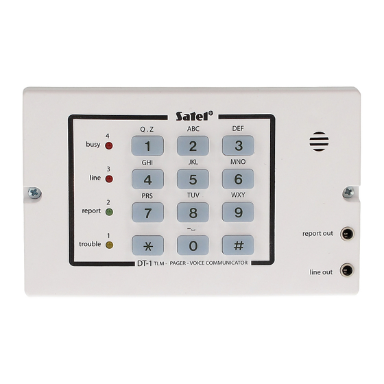
4.2 K EYPAD The format of DT-1 keypad is typical for telephones. Letters placed on keys facilitate the programming of text messages for pager systems. During data programming, [#] is used for accepting, and [ * ] stops programming. The use of keys is confirmed by a sound signal. -
Page 11: P Rogramming – U Ser F Unctions
DT-1 SATEL 5. P – U ROGRAMMING UNCTIONS User functions are available only after the programming mode is activated by user's code finished with the [#] key. To confirm that the programming mode has been activated, the dialer will generate four short sounds and one long sound signal and the TROUBLE LED will start flashing. -
Page 12: Function 7 – Recording Voice Messages
User Manual DT-1 and pressing [#]. Each pressing of the [#] key will show the subsequent digit or code. Number review is stopped after the sixteenth character or digit and is signalled by three short sounds. To leave the telephone number programming (or reviewing) function immediately, press [ * ] and [#]. -
Page 13: Function 8 – Message Control
DT-1 SATEL ([7][#]), the dialer generates a short sound and starts the recording of the first message. After approximately 8 seconds there is a break in the recording, the dialer generates two short sounds and starts the recording of the second message. After another 8 seconds the recording is finished and the dialer generates three short sounds, signaling the end of the function operation. -
Page 14: Fs0 – Leaving The Service Mode
User Manual DT-1 digit key with the LED number. After all options are set in a given function, confirm the settings by pressing [#]. Functions from FS15 to FS33 are used for the programming of data connected with the monitoring. -
Page 15: Fs4 – Phoning Options (Part Ii)
DT-1 SATEL FS4 – PHONING OPTIONS (PART II) Option Control key answering external phone calls enabled BUSY answering external phone calls disabled breakdown sound signal enabled LINE breakdown sound signal disabled telephone exchange answer signal testing disabled REPORT telephone exchange answer signal testing enabled... -
Page 16: Fs6 – Specification Of Numbers For Pager System (Part I)
User Manual DT-1 • Transmission with event distribution (option 2) consists in the sending of codes of alarm events to the first monitoring station, and all other codes to the second station. • Option 1 is taken into consideration when option 3 is switched off. -
Page 17: Fs10 – Setting Time For The Sending Of A Test Code To Station
DT-1 SATEL – [1][#] enter the first hour digit, – [2][#] enter the second hour digit, – [4][#] enter the first minute digit, – [5][#] enter the second minute digit; leave the function after pressing [#] Note: During the programming, LEDs show (in binary code) the subsequent digits of the current dialer time. -
Page 18: Fs15 – Programming Of Identifier For The First Monitoring Station
User Manual DT-1 The programming of the numbers is the same as for user functions (see description of functions F1 to F6). FS15 – PROGRAMMING OF IDENTIFIER FOR THE FIRST MONITORING STATION FS16 – PROGRAMMING OF IDENTIFIER FOR THE SECOND MONITORING... -
Page 19: Fs20 – Alarm Restore Code Programming
DT-1 SATEL FS20 – ALARM RESTORE CODE PROGRAMMING This function defines the code to be sent to the monitoring station when the ALARM input records the disappearance of the "alarm" status (alarm status is defined by the option in FS2). -
Page 20: Fs32 – Service Mode Leaving Code Programming
User Manual DT-1 FS32 – SERVICE MODE LEAVING CODE PROGRAMMING FS33 – DIALER RESTART CODE PROGRAMMING This code is sent upon the restarting of the dialer processor system (e.g. after the power is turned on after end of a power failure). -
Page 21: Fs35 – Programming Message "A" To Polpager
DT-1 SATEL EXAMPLE: PROGRAMMING A MESSAGE TO POLPAGER: Keys used during Codes entered Keys used in the dialer Message the sending of the to dialer to enter data message by phone select text mode [ * ][1][#][ * ][1][#] [2][#][ * ][1][#]... -
Page 22: Fs36 – Restoration Of Manufacturer's Settings
- telephone numbers not programmed, - monitoring stations telephone numbers not programmed, - all monitoring codes equal to zero, - phoning, answering calls and monitoring disabled, - message = ALARM-SATEL in the POLPAGER format, - co-operation with POLPAGER. EXAMPLE: restoration of manufacturer's settings. -
Page 23: Fs37 – Programming Parameters Of The Pager System Station Signal
Note: Selecting the two-message mode (LED 2 on) results in ascribing telephone numbers to message numbers on a permanent basis, as described in the chapter "About DT-1”. This work mode also applies to the forwarding of messages to pager systems. - Page 24 User Manual DT-1 • switch on the power (the dialer should confirm activation of the service mode by four short sounds followed by one long sound), • remove the jumper from RESET pins and select function FS36. 7. T ECHNICAL...
-
Page 25: Technical Data
DT-1 SATEL – alarm signal input – alarm system on signal input – additional alarm signal input +12V – power supply – common – protective terminal – ground (connect to protective circuit only) TECHNICAL DATA Power supply .............DC 11 to 16V (typical for alarm systems) Power consumption .........on average 30mA (max. -
Page 26: User Functions
User Manual DT-1 CA-4V1 Control Panel Dialer DT-1 Output programming: Input programming: function 8: in service function 2: - OUT 2 output informs about the "on" status by - ALM input reacts to "0" "0" (program 000) - ARM input reacts to "0". - Page 27 DT-1 SATEL 5 monitoring options 4 |_| – disabling 3 |_| – transmission to two monitoring stations 2 |_| – event distribution (SPLIT REPORTING) 1 |_| – transmission to station 2, when 1 unavailable 6 telephone numbers to 4 |_| – telephone number 4 = pager number pager systems 3 |_| –...
-
Page 28: Display Codes
User Manual DT-1 29 alarm switched off from keypad code |_|_| (**) 30 programming switched on code |_|_| (**) 31 service mode switched on code |_|_| (**) 32 service mode switched off code |_|_| (**) 33 dialer RESTART code |_|_| (**) -
Page 29: H Istory Of The Manual Updates
• A remark on the dialer restarting has been added (p. 23). • An illustration of PCB for laminate in version 3.1 (p. 22) 2004-06-15 • The earlier symbol of DT-1 device and the new program version number 2006-05-12 is added on the cover. - Page 30 An efficient security system does not prevent burglary, assault or fire from happening, however it diminishes the risk that such a situation will cause no alarm or notification. Therefore, the SATEL Company recommends that operation of the whole security system be regularly tested.
Need help?
Do you have a question about the DT-1 and is the answer not in the manual?
Questions and answers