
Related Manuals for MBW 973-SF6

Summary of Contents for MBW 973-SF6
- Page 1 Analyzer 973 Operation Manual Version 973-SF V3.1 MBW Calibration Ltd. Seminarstrasse 57 CH-5430 Wettingen / Switzerland +41 56 437 28 30 Phone +41 56 437 28 40 Fax sales@mbw.ch www.mbw.ch...
- Page 3 Table of Contents TABLE OF CONTENTS ..................I GENERAL ......................1 SHORT DESCRIPTION ..................3 OPERATION....................... 5 Front Panel without SO Option ....................5 Front Panel with SO Option ...................... 5 Back Panel without SO Option ....................8 Back Panel with SO Option ......................
- Page 4 TEST FUNCTIONS ................... 31 Ice Test ............................ 31 ADDITIONAL SETTINGS ................. 35 Selection of Languages ......................35 Selection of the indicated Parameters ..................36 Selection of Units ........................37 Changing Color ........................38 Storage of the Actual Settings ....................39 Restore Color Settings and Baud Rate ..................
-
Page 5: General
General This manual explains the function of the 973-SF Analyzer with and without the SO option. Throughout this manual the instrument will be called 973. This manual refers to instrument software versions 110525a and higher. Should the 973 be used in any other way than that described in this user’s manual, or outside the limits described, the built-in safety pro- tection of the instrument may be compromised. - Page 6 MBW973-SF6_MANUAL_E_V3.1...
-
Page 7: Short Description
Short Description Reliable Measurements in SF The 973 was specifically designed for measurement of humidity, SF purity and SO concentra- tion in gas insulated switchgear systems. Humidity measurement data is displayed in ppm and Frost/Dew Point at either gas compartment pressure or standard pressure. SF purity measurement is displayed directly in % Volume SF . - Page 8 MBW973-SF6_MANUAL_E_V3.1...
-
Page 9: Operation
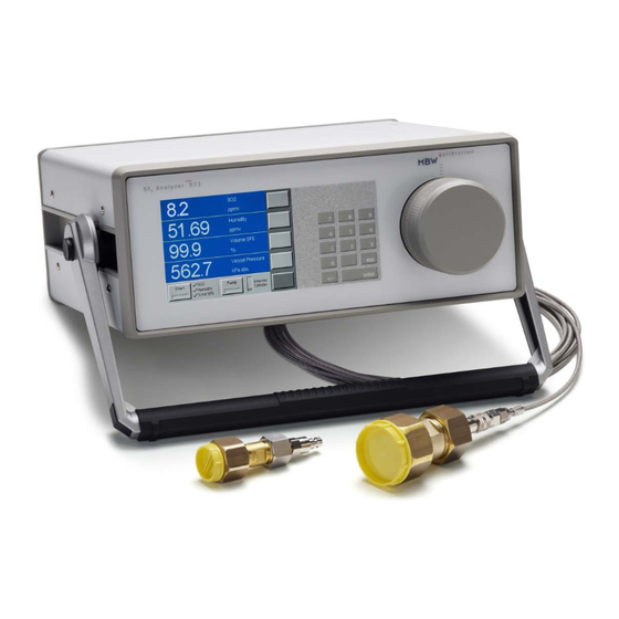
Operation Front Panel without SO Option Touch Screen Data Lines Status of Measurement Keypad Measuring Head Menu Keys Fixed Function Keys Internal Cylinder Capacity Front Panel with SO Option MBW973-SF6_MANUAL_E_V3.1... -
Page 10: Data Lines
Data Lines The first four lines of the display are for numeric representation of the measured data. We refer to those first four lines as Data Lines. Numeric data lines contain the value to the left, with the parameter description and units to the right. The displayed parameters and units can be changed, but after a restart of the instrument, the values will be reset to the stored standard configuration. - Page 11 Menu Keys To the right side of the display is a column of menu keys. Each of these keys changes function as needed. Use the Note that the bottom key in this column is different bottom from the rest. The bottom key is used to cycle the key to upper keys through the various menu options.
- Page 12 Back Panel without SO Option Gas Inlet Quick Coupling RS-232 Serial Interface Power Socket with Main Switch Back Panel with SO Option Optional SO Sensor with Calibration Date and Replacement Date MBW973-SF6_MANUAL_E_V3.1...
-
Page 13: Power Connection
Power Connection The AC power cord is connected to the power socket on the instrument back panel. The power socket also includes the power switch. The power supply voltage is 100-120 VAC / 200-240 VAC at 50 to 60Hz. The power supply is internally fused and will automatically switch off in case of an overload. - Page 14 MBW973-SF6_MANUAL_E_V3.1...
-
Page 15: Initial Setup
Initial Setup Preparation The 973 needs a source of normal AC power. The label on the back panel indicates the ac- ceptable input voltage range. The instrument has been designed to work with a power range between 100-120 VAC / 200-240 VAC at 50 to 60 Hz. This normally covers all usual AC line voltages. - Page 16 Gas Connection The quick coupling on the instrument side of the sampling tube must be connected to the SAMPLE GAS inlet. Note: To prevent contamination, the blue cover caps of the instru- ment and sampling tube should always be installed when the instrument is not in use.
-
Page 17: Evacuate The Sampling Tube
Evacuate the Sampling Tube The sampling tube must be evacuated before the first initial measurement is started. Once ini- tially evacuated, there is no need to re-evacuate the hose, even when moving the connection to the next compartment. Make sure that a SF coupling DN8 or DN20 is properly in- stalled on the sampling tube, but do not connect the SF coupling to anything else at this time. -
Page 18: Evacuate The Internal Cylinder
Evacuate the Internal Cylinder If the content of the internal cylinder is unknown, or contaminated SF gas is stored inside it, the internal storage cylinder can be evacuated. Press the Evacuate Internal Cylinder key in the Control Setup menu. The dialogue box requests you to remove the sampling gas tube or connect an SF reclaimer to the 973. - Page 19 Gas Connection to the Compartment If the sampling tube was properly evacuated before the first measurement, it is now ready to connect to the gas com- partment. When moving the connection from compartment to compartment, there is no need to re-evacuate. Remove the dust caps from fittings, check both threads are clean, carefully screw on the fitting and ensure a good seal is made.
- Page 20 MBW973-SF6_MANUAL_E_V3.1...
-
Page 21: Measurement Options
Measurement Options Navigating the Menus The various menus of the right column of keys are navigated by using the key in the lower right corner of the touch screen. Each time you press the lower right key, a new menu appears on the keys directly above it. - Page 22 Measuring Mode Examples The examples shown include the measuring options for the 973 when equipped with the SO option. When there is no SO module fitted to the instrument, the SO2 Measurement button is disabled and cannot be selected. For the purpose of this example, select only Humidity Measurement, and disable SO2 Measurement, % Vol SF6 Measurement and Pump Back After Measurement.
-
Page 23: Measurement
Measurement Measurement without SO Option This section describes the measurement sequence for the 973 without the SO option. Please refer to page 21 for the equivalent procedure for instruments equipped with the SO option. If you intend to collect the measurement data automatically, please install the Excel Protocol sheet, as described on page 25, before the start of the measurement. -
Page 24: Termination Of Measurement
After completion of the % volume SF measurement, the spinning clock stops and the measured % volume SF displayed. Finally, the pump back starts and the trend arrows and level indicator show the decreasing pressure of the internal stor- age cylinder. The mirror is heated at the same time, indi- cated by the red Start key. - Page 25 Measurement with SO Option The section describes the measurement procedure for the 973 equipped with the SO option. Refer to page 19 for equivalent procedures for instruments without the SO option. If you intend to collect the measurement data automatically, please install the Excel Protocol sheet, as described on page 25, before the start of the measurement.
-
Page 26: Termination Of Measurement
After completion of the % volume SF measurement, the spinning clock stops and the measured % volume SF displayed. Finally, the pump back starts and the trend arrows and level indicator show the decreasing pressure of the internal stor- age cylinder. The mirror is heated at the same time, indi- cated by the red Start key. -
Page 27: Measuring Range Limitations
Measuring Range Limitations The lower measuring limits of the 973 are approximately 40 ppm (depending on pressure) for humidity and 80% for volume SF . If the measured value for humidity or % volume SF is below this measuring limit, the instrument indicates these conditions as follows: If the measured value of humidity is below the measuring <... -
Page 28: Measurement Aborted
Measurement Aborted If the measurement is aborted due to low or high pressure conditions, the 973 will heat up the mirror, restore the measuring head pressure to 100 kPa abs (approximately atmospheric pres- sure), and stop. Pump back of the stored gas in the internal cylinder can be started by pressing the Pump key. -
Page 29: Data Collection In Excel
Data Collection in Excel RS-232 – USB Converter Installation On the CD-ROM 973-SF you will find the drivers for the Keyspan RS-232 / USB Adapter. Double click on: KeyspanUSA19hsWinVXX.exe (XX = equals Version No. supplied on CD) and follow the installations instructions. The pro- gram is stored by default in the folder C:\Program\Keyspan\USB Serial Adapter. -
Page 30: Data Collection Over Rs-232 With The Excel Protocol
Excel Protocol. On the CD-ROM 973-SF you will find the 973-SF protocol. Double click on: 973-SF6 Protocol VXX 973-SF6 Protocol VXX (XX = equals Version No. supplied on CD) After opening the 973-SF protocol the safety warning may appear. - Page 31 Point, Moisture Content and SF6 Vol remain stored in the 973 until the next measurement is started. The instrument type and serial number are auto- Instrument ID: 973-SF6 Instrument S/N: 05-0714 matically stored in the last line at the bottom of the page Note that data communication can be accom- plished after completion of the measuring cycle.
- Page 32 MBW973-SF6_MANUAL_E_V3.1...
- Page 33 Module The 973 internal SO module provides the user with the capability to measure SO concentra- tion in SF gas compartments. The module is conveniently mounted on the back panel of the instrument with the sample gas connections internally connected. The module uses an electrochemical cell specifically for SO .
-
Page 34: Replacement Of So 2 Measurement Cell
Activation of SO Measurement If you have an instrument without SO measurement, but with the serial number 12-0000 or higher, then your instrument is “SO ready”. Meaning, in order to enable the SO measurement only the installed measurement cell cover needs to be replaced with an SO sensor. -
Page 35: Test Functions
Test Functions Ice Test The measuring accuracy can be checked with a simple, built-in test. The test may be performed at any time, and is recommended if the results of your normal measurements do not correspond to expectations and an error is assumed with the instrument. Press the lower right menu key once to select the Control Setup menu. - Page 36 Once the screw cover has been removed, the black optical assembly (optical head) is now removed by pulling it straight toward you. The mirror is now visible and you are ready to perform the Ice Test. Confirm that you opened the measuring head and are ready for the Ice Test by pressing the Ok button.
- Page 37 If the measured ice-melt temperature was in the range of ± 0.2 °C, the check is successful and will be indicated with the calibration status PASS. If the measured ice-melt temperature was outside the range of ± 0.2 °C, the check was not successful and will be indicat- ed with the calibration status FAIL.
- Page 38 MBW973-SF6_MANUAL_E_V3.1...
-
Page 39: Additional Settings
Additional Settings Selection of Languages The menus of the 973 can be displayed in different languages. In order to set the system to your preferred language, proceed as follows: Press the lower right menu key repeatedly to select the Other Settings menu. Then press the Language key until your preferred language is displayed. -
Page 40: Selection Of The Indicated Parameters
Selection of the indicated Parameters Selecting which parameter to display on the four data lines is easy. It is done with the Parame- ter menu. Press the lower right menu key a couple of times to select the Parameter menu. Note that each of the upper keys cor- respond to the data lines they point toward. -
Page 41: Selection Of Units
Selection of Units The data may be viewed in any of the many available units. Use the lower right menu key to select the Units menu. Units appears on the key and the keys above show the various units. Note that each of the keys shows different types of units. -
Page 42: Changing Color
Changing Color You are free to change the foreground and/or background color of any data line with the Fore Color and Back Color menus. Access the Fore Color and Back Color menus with the menu selection key. To revert to the standard system default color scheme, press and hold the 9 key for a few seconds (see page 40). -
Page 43: Storage Of The Actual Settings
Storage of the Actual Settings The 973 is delivered with a standard configuration. Options you change during normal use are not saved and the instrument reverts to its default settings after cycling the power. You may however store your current configuration settings as the power-up default for this instrument. Save your customized configuration as the default with the following: Press and hold the number 1 on the keypad for about 5 seconds. -
Page 44: Restore Color Settings And Baud Rate
Units Absolute or Relative Pressure Mode The default configuration includes the units for all parame- ters as well as the absolute or relative pressure mode. Parameters The default configuration includes the parameter selection of the data lines. Colors The default configuration includes the front and back- ground colors selection. -
Page 45: Maintenance
Maintenance Touch Screen Calibration The 973 utilizes a touch screen for user interaction. To activate a menu option or toggle a func- tion on or off, simply touch the screen directly over the key or object desired. Before using the instrument for the first time, or when the instrument is used by different opera- tors, you may need to calibrate the touch screen to your finger positioning preference. -
Page 46: Mirror Cleaning
Mirror Cleaning The heart of the 973 is the measuring head assembly. It is designed to be highly sensitive and accurate, yet rugged and easily accessible for periodic mirror cleaning. To ensure high accura- cy, the mirror should be cleaned before starting a series of measurements. After removing the screw cover and the measuring head optical assembly, the mirror is easily accessible. -
Page 47: Exterior Cleaning
Inspecting / Cleaning the Mirror Clean the mirror with a clean cotton swab or lint free tissue. Note: • Never attempt to polish the mirror. • If needed, the mirror may also be cleaned with methanol or alcohol. Always follow the use of these cleaning chemicals with distilled water to ensure they are completely rinsed from the mirror surface. - Page 48 MBW973-SF6_MANUAL_E_V3.1...
-
Page 49: Specifications
Specifications Specifications 973-SF Measuring Range: Frost/Dew Point -50…+20 °C Humidity content by volume 40…20’000 ppm Humidity content by weight 5…2’500 ppm Volume SF 80…100% Inlet pressure 120…1’000 kPa abs. Accuracy: Frost/Dew Point ± 0.5 °C / ppm ± 1 ppm +6% of reading Volume SF ±...
Need help?
Do you have a question about the 973-SF6 and is the answer not in the manual?
Questions and answers