Table of Contents
Advertisement
Quick Links
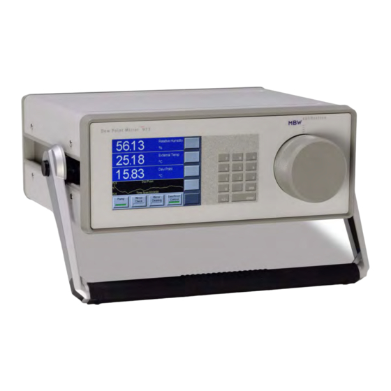
Dew Point Mirror 973
Maintenance Manual
MBW Calibration Ltd.
Seminarstrasse 57
CH-5430 Wettingen / Switzerland
+41 56 426 21 33 phone
+41 56 427 14 00 fax
0Hwww.mbw.ch
info@mbw.ch
UK Distribution by IMA Ltd:
Parkwell House,
Otley Road,
Guiseley, West Yorkshire,
LS20 8BH, England
Phone: +44 (0)1943 878877
Email: info@ima.co.uk
Web: www.ima.co.uk
Operation and
Advertisement
Table of Contents

Related Manuals for MBW 973

Summary of Contents for MBW 973
- Page 1 Dew Point Mirror 973 Operation and Maintenance Manual MBW Calibration Ltd. Seminarstrasse 57 CH-5430 Wettingen / Switzerland +41 56 426 21 33 phone +41 56 427 14 00 fax 0Hwww.mbw.ch info@mbw.ch UK Distribution by IMA Ltd: Parkwell House, Otley Road,...
- Page 2 MBW. MBW will not be liable for any other claims or damages, either direct, indirect, or consequential arising out of the use of its...
-
Page 3: Table Of Contents
How to Use This Manual ......................1 For More Information ......................1 OPERATION......................3 Getting Started......................... 3 Turning the 973 On and Off ....................3 What You See ........................3 The Touch Screen........................5 The Measuring Head Assembly..................... 9 Dew Point Measurement......................9 System Configuration ...................... - Page 4 REMOTE COMMUNICATION ................29 Introduction..........................29 Hardware Connection & Cabling..................29 Communications Settings ....................30 Command Syntax ........................30 General Usage ........................30 Termination Characters ....................... 30 Leading and Trailing Spaces ....................31 Case Sensitivity........................31 Numeric Values........................31 Command Reference......................32 Commands Listed By Functional Group ................
-
Page 5: Welcome
973 and start using it right away. 1. With the 973 at hand, go straight to the Getting Started section on page 3. From there, you can quickly learn to use the 973 to make a dew point measurement. -
Page 7: Operation
Turning the 973 On and Off The 973 needs a source of normal AC power. Have a look at the label on the back panel of the instrument for the voltage required. Ensure that the required voltage matches that of your standard laboratory power receptacles. -
Page 8: Data Lines
Data Lines The first four lines of the display are for numeric or graphic representation of the measured data. We refer to those first four lines as data lines. If numeric, a data line contains the value to the 10.00 Relative Humidity left, with the parameter description and units to the right. -
Page 9: The Touch Screen
Calibrate the Touch Screen Before using the 973 for the first time, you may need to calibrate the touch screen to your finger positioning preference. Here’s how –... - Page 10 Navigating the Menus The various menus of the right column of keys are navigated by using the key in the lower right corner of the touch screen. Each time you press the lower right key, a new menu appears on the keys directly above it.
- Page 11 Selecting Graph vs. Numeric Data Any data line may be viewed either as numeric or as a graph. The Numeric/Graphic menu is used to toggle any data line between numeric and graph mode. 1. Use the lower right menu key to select the Numeric/Graphic menu.
- Page 12 Selecting Units The data may be viewed in any of the many available units. There are two Units menus used to change the units of displayed data. 1. Use the lower right menu key to select the Units menu. ‘Units’ appears on the key, and the keys above contain current units indications such as ‘Temp °C’.
-
Page 13: The Measuring Head Assembly
Cleaning on page 37. Dew Point Measurement When you power the 973 on, it begins in an idle state. In this state, it measures and displays temperature, pressure, and flow transducers, but does not yet provide any meaningful humidity related data. In order to provide humidity data (dew point, frost point, %RH, etc.), the Dew/Frost Control mode must be enabled and gas must be flowing across the mirror. - Page 14 While the previous example did not rely on any external gas connections, the 973 is equipped with fittings for connection of gas inlet and outlet tubing. This allows the 973 to measure the dew or frost point of chambers and other devices that can be connected to it via tubing. If you have a gas source you wish to measure, such as a humidity generator or chamber, connect a tube between it and the 973 gas inlet on the back of the unit.
- Page 15 Swagelok® brand tube fittings are generally used to connect the gas inlet and outlet tubes to the 973 system. Depending on the configuration of your specific 973, the back panel fittings are either ¼” or 6 mm. When ordering tube fittings from your local Swagelok® supplier, be sure to specify the correct size for your instrument.
-
Page 16: System Configuration
Each time you press this menu key, the 973 advances to the next menu and the key’s label changes to indicate which menu is currently active. Once you’ve reached the last menu item, and press the menu key again, the menu options just start over again at the beginning. -
Page 17: Display Parameters
Head Temperature Graphing Data Any value that you can view numerically can also be viewed as a graph at any time. The 973 automatically maintains a short history of each and every selectable parameter so that a graph may be seen instantly whenever a data line is toggled from a numeric mode to a graph mode. - Page 18 This is very useful for data that is very stable with little variation. This prevents the 973 from setting the scaling to such a small range that even the highly stable data appears visibly as wildly variable. For viewing dew or frost point graphs, setting this Autoscale Minimum to a value of at least 0.2 or more is generally preferable.
-
Page 19: Control Setup
6. Dew / Frost Control The 973 can control on either dew point or frost point, and has the ability to distinguish the difference through a function known as Force Frost. The Dew / Frost Control setup menu is used to control the Force Frost function and also allows for setup of the ORIS (Optimal Response Injection System) operation. - Page 20 2°C. To eliminate this problem, the 973 can automatically force all sub-zero condensation to a known state of frost using the Force Frost function. Force Frost works by rapidly cooling the mirror below –40°C forcing the condensate to solidify to a layer of ice or frost.
- Page 21 Mirror Check Control Mirror Check is the process of warming the mirror to evaporate all condensation, look for the presence of contamination and account for it if necessary, then re-initiating a new dew or frost point measurement. Mirror Check may be initiated manually with the fixed Mirror Check key, or if enabled to do so, it may trigger automatically at pre-specified time intervals.
-
Page 22: Changing Units
Changing Units You can display system data in any of a wide variety of units. When you make a new units selection, that selection remains until you change it again. To change units, follow the instructions given in the Selecting Units section on page 8. Units selections are global across the system, meaning that all values of that parameter type change to reflect the chosen units. -
Page 23: Changing Color
Specific Humidity Units Specific humidity may be displayed in units of g/g, g/kg, and lb/lb. When changing these units, specific humidity will change to reflect the new units selection, whether displayed numerically or as a graph. Notice that the chosen units will appear on the screen both on the units selection key and next to specific humidity when displayed. -
Page 24: Analog Outputs
Analog Outputs If this option is installed, the 973 is equipped with at least two analog outputs that are independently configurable. For each of the analog outputs, you may easily select which parameter to track and how to scale the selected parameter to the analog output range. These selections are made for each of the analog outputs via the Analog Outputs menu. - Page 25 Min Voltage Max Voltage Depending on the factory configuration and calibration of your specific 973, it may be equipped with one of several different output options. Options have included ±1, ±5, or ±10 VDC. Additionally, some units have been equipped with 4-20 mA outputs. While the most common option is ±10 VDC (with 16-bit resolution), many older units where equipped with ±5 VDC (with...
-
Page 26: Back Panel Connections
The RS-232 connector is used when connecting the 973 to an external computer. Use a standard 9 pin cable to connect between the 973 and a desktop or laptop computer. The cable is wired straight through with pins 1 through 9 of the male end wired to pins 1 through 9 respectively of the female end. -
Page 27: Analog Outputs
1. Gas Input and Output The gas input and output fittings are used for connection of the 973 to the sample gas. Based ® on the original configuration of your system, it will generally contain ¼” or 6 mm Swagelok tube fittings. -
Page 28: Measurement Tips
Understand the Measuring Range The 973 has a specific dew / frost point measuring range. It also has a specific range of temperature that it can measure. These values are also converted into the appropriate relative humidity measurement range. The typical 973 measurement range is listed below. - Page 29 Hose Input and Output Preferred Connections When comparing two or more instruments, make the connections in parallel. Pump Flow Pump Flow Troublesome Connections Never connect instruments in series, because of the interference between the two instruments. Pump Flow Pump Flow Measurement Tips 25...
-
Page 30: Cooling Requirements
Cooling Requirements Air Cooling All 973 systems are equipped with air cooling. When air cooled, the fan speed is controlled automatically by the computer. Air cooling is generally sufficient for measurements of frost/dew points from approximately –50 to +20°C. Air cooling operates automatically and requires no user input. -
Page 31: Installation
Prior to first measurement the instrument should be switched on for 30 minutes to warm up. Benchtop Use All 973 models are ready for benchtop use. Bench space of at least 24” x 24” (0.6 x 0.6 m) is recommended. -
Page 33: Remote Communication
The 973 ignores the DSR and CTS handshaking signals. While there is no harm in connecting all 9 pins, the 973 only requires connection of three of the pins (pins 2=TxD, 3=RxD and 5=GND). For your reference, the complete connector pin-out is listed in the following table. -
Page 34: Communications Settings
Automatic Mirror Check timing interval.. AMC.cycleTime? The 973 replies with the current AMC cycle time. This value may have been entered from the touch screen or as you will now see, via RS-232. When setting new values or parameters, use =, the equal sign. For example, the following command changes the Automatic Mirror Check timing interval to 20 minutes. -
Page 35: Leading And Trailing Spaces
Numeric Values All numeric data sent to or received from the 973 is done so in either standard or scientific notation. Sending a number as 12.34 is the same as sending it as 1234e-2 or as 1.234e1. -
Page 36: Command Reference
Some values simply require integer numbers such as 1 and 0 for On and Off, while others might need real numbers with a decimal point. The 973 recognizes both types of numbers and will attempt to convert the values you send to the correct format. For example, the number 0 means Off, while 1 or any other real or integer value means On. -
Page 37: Commands Listed By Functional Group
Temperature to cool to in order to force frost, °C ForceFrost.holdBelow[=n][?] Keep mirror below this temp during force frost, °C ForceFrost.dispHold[=i][?] 1 freezes DP display during Force Frost SaveCfg=973 Save these and other configuration parameters Water Valve Settings Syntax Function WaterValve.armed? - Page 38 ORIS Settings Syntax Function UseOris.on[=i][?] 1 enables ORIS, 0 disables ORIS UseOris.below[=n][?] Temperature below which ORIS activates, °C SaveCfg=973 Save these and other configuration parameters Mirror Cleaning Preparation Syntax Function MinHeadRemovalTemp[=n][?] Head and inner cooler are warmed above this temp when Mirror Cleaning button has been pressed prior to head removal, °C...
- Page 39 Ana2.hold[=i][?] 1 Calibration mode. Analog output is set with the command Ana2.output=n. 0 Normal mode. Analog output tracks the parameter set with Ana2.param=i. SaveCfg=973 Save these and other configuration parameters Mirror Temperature Calibration Coefficients Syntax Function MirrorTempCal.r0[=n][?] Callendar VanDusen R0 coefficient, ~ 100.00 MirrorTempCal.a[=n][?]...
- Page 40 Save these and other calibration parameters System Identification Syntax Function Returns a string containing instrument identification, ie. DPM 973 IDN? Returns only numeric portion of identifier, ie. 973 Saving Changes Syntax Function SaveCfg=973 Save configuration parameters SaveCal=973 Save calibration parameters...
-
Page 41: Maintenance
Maintenance Mirror Cleaning The heart of the 973 dew point measuring instrument is the measuring head assembly. It is designed to be highly sensitive and accurate, yet rugged and easily accessible for periodic mirror cleaning. Removing the Head Cover Screw or Retaining Bar The measuring head is located on the right side of the 973 front panel. -
Page 42: Exterior Cleaning
Guide Pin Exterior Cleaning Front Panel The 973 front panel is completely sealed and easily cleaned with liquid glass cleaner or other mild cleaning chemicals moistened on a cloth. Clean the front panel periodically as needed. Rear Fan Grills The rear fan grills may require cleaning periodically to ensure adequate airflow within the system.
Need help?
Do you have a question about the 973 and is the answer not in the manual?
Questions and answers