Table of Contents
Advertisement
Quick Links
Advertisement
Table of Contents

Related Manuals for thomann Stairville Tri Flat PAR Profile 5x3W RGB


Summary of Contents for thomann Stairville Tri Flat PAR Profile 5x3W RGB
- Page 1 Tri Flat PAR Profile 5×3W RGB LED PAR user manual...
- Page 2 Musikhaus Thomann e.K. Treppendorf 30 96138 Burgebrach Germany Telephone: +49 (0) 9546 9223-0 E-mail: info@thomann.de Internet: www.thomann.de 20.06.2013...
- Page 3 Table of contents Table of contents General notes............................... 5 Safety instructions............................. 8 Features............................... 12 Installation..............................13 Starting up..............................17 Connections and operating elements................... 20 Operating..............................31 7.1 Starting the device........................... 31 7.2 Operating the device directly...................... 31 7.3 Menu overview..........................37 7.4 Remote control..........................
- Page 4 Table of contents Plug and connection assignments....................46 Troubleshooting............................47 Cleaning............................... 50 Protecting the environment......................51 LED PAR...
-
Page 5: General Notes
General notes General notes This user manual contains important information on safe operation of the device. Read and follow all safety notes and all instructions. Save this manual for future reference. Make sure that it is available to all persons using this device. If you sell the device, include the manual for the next owner. - Page 6 General notes Signal word Meaning DANGER! This combination of symbol and signal word indicates an immediate dangerous situation that will result in death or serious injury if it is not avoided. WARNING! This combination of symbol and signal word indicates a possible dangerous situation that can result in death or serious injury if it is not avoided.
- Page 7 General notes Warning signs Type of danger Warning – suspended load. Warning – danger zone. Tri Flat PAR Profile 5×3W RGB...
-
Page 8: Safety Instructions
Safety instructions Safety instructions Intended use This device is intended to be used as an electronic illumination effect using LED technics. Use the device only as described in this user manual. Any other use or use under other operating conditions is considered to be improper and may result in personal injury or property damage. No liability will be assumed for damages resulting from improper use. - Page 9 Safety instructions DANGER! Electric shock caused by high voltages inside Within the device there are areas where high voltages may be present. Never remove any covers. There are no user-serviceable parts inside. DANGER! Electric shock caused by short-circuit Always use proper ready-made insulated mains cabling (power cord) with a pro‐ tective contact plug.
- Page 10 Safety instructions WARNING! Eye damage caused by high light intensity Never look directly into the light source. WARNING! Risk of epileptic shock Strobe lighting can trigger seizures in photosensitive epilepsy. Sensitive persons should avoid looking at strobe lights. NOTICE! Risk of fire Do not cover the device nor any ventilation slots.
- Page 11 Safety instructions NOTICE! Operating conditions This device has been designed for indoor use only. To prevent damage, never expose the device to any liquid or moisture. Avoid direct sunlight, heavy dirt, and strong vibrations. NOTICE! Power supply Before connecting the device, ensure that the input voltage (AC outlet) matches the voltage rating of the device and that the AC outlet is protected by a residual current circuit breaker.
-
Page 12: Features
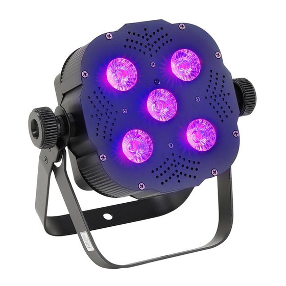
Features Features The LED PAR is particularly suitable for professional lighting applications, for example, at events, on rock stages, in theatres and musicals. It is characterized by low power consumption and a long service life. Special features of the device: Five tri-colour LEDs (red, green, blue), 3 W each Control via DMX (3 different modes), or with the included infrared remote control and via buttons and display on the unit... -
Page 13: Installation
Installation Installation Unpack and carefully check that there is no transportation damage before using the unit. Keep the equipment packaging. To fully protect the device against vibration, dust and moisture during transportation or storage use the original packaging or your own packaging material suitable for transport or storage, respectively. - Page 14 Installation NOTICE! Risk of overheating Always ensure sufficient ventilation. The ambient temperature must always be below 40 °C (104 °F). NOTICE! Use of stands When mounting the device onto a stand, ensure that the stand is in a safe and stable position and that the weight of the device does not exceed the maximum permissible load capacity of the stand.
- Page 15 Installation NOTICE! Possible data transmission errors For error-free operation make use of dedicated DMX cables and do not use ordi‐ nary microphone cables. Never connect the DMX input or output to audio devices such as mixers or ampli‐ fiers. Infrared receiver for remote The infrared sensor for the remote control signals is located on the front panel near the middle control LED.
- Page 16 Installation Inserting the battery into the Press the lock of the battery holder to the centre of the housing and pull out the battery holder remote control like a drawer. Insert the battery. The battery is correct if the positive pole points to the housing base of the remote control.
-
Page 17: Starting Up
Starting up Starting up Establish all connections as long as the unit is switched off. Use the shortest possible high- quality cables for all connections. Tri Flat PAR Profile 5×3W RGB... - Page 18 Starting up Connections in DMX mode Connect the DMX input of the device to the DMX output of a DMX controller or another DMX device. Connect the output of the first DMX device to the input of the second one, and so on to form a daisy chain.
- Page 19 Starting up DMX indicator If the unit is in DMX mode and a DMX controller is connected and turned on, the ‘d’ flashes in the first position of the display. Connections in master/slave When you configure a group of devices in master/slave mode, the first unit will control the mode other units for an automatic, sound-activated, synchronized show.
-
Page 20: Connections And Operating Elements
Connections and operating elements Connections and operating elements Overview LED PAR... - Page 21 Connections and operating elements 1 Front panel. 2 Infrared sensor for the remote control signals. 3 Bottom side with inputs (DMX and voltage supply). 4 Locking screws for the mounting brackets. 5 Rubber foots for setup. 6 Operating elements at the side. 7 Top side with outputs (DMX and voltage supply for further devices).
- Page 22 Connections and operating elements Top side LED PAR...
- Page 23 Connections and operating elements 16 DMX Out DMX output. 17 Openings for safety rope. 18 POWER Out IEC chassis socket for the power supply cable to the next device. Tri Flat PAR Profile 5×3W RGB...
- Page 24 Connections and operating elements Bottom side LED PAR...
- Page 25 Connections and operating elements 9 POWER In IEC chassis connector for operating voltage supply with fuse holder. 10 DMX In DMX input. Tri Flat PAR Profile 5×3W RGB...
- Page 26 Connections and operating elements Side-mounted operating ele‐ ments LED PAR...
- Page 27 Connections and operating elements 11 Display. 12 Button [Down] For downward navigation in a menu list. Decreases the displayed value by one. 13 Button [Up] For upward navigation in a menu list. Increases the displayed value by one. 14 Button [Setup] Selects an option of the respective operating mode.
- Page 28 Connections and operating elements Remote control LED PAR...
- Page 29 Connections and operating elements 21 [BLACK OUT] Enables or disables blackout. 22 [AUTO] Enables or disables auto mode. 23 [SOUND] Starts the sound-controlled automatic show. 24 [SPEED] Allows setting the speed for the flash light function using the [+] and [–] buttons. 25 [SENSITIVITY] Allows setting the sensitivity for the sound control using the [+] and [–] buttons.
- Page 30 Connections and operating elements 28 [STROBE] Enables or disables the flash light function (strobe effect) with the last selected colour. 29 [MANUAL] Activates the display of a constant colour that you can either mix from the basic colours using the buttons [R], [G] and [B], or select directly with one of the colour buttons.
-
Page 31: Operating
Operating Operating 7.1 Starting the device Connect the device to the power supply to start operation. After a few seconds, the display indicates that a reset is in progress. The device is then ready for use. 7.2 Operating the device directly Press [Mode] to activate the main menu and select an operating mode. - Page 32 Operating Operating mode ‘Preprog‐ A preprogrammed automatic show can only be activated when the unit is working alone or as rammed automatic show’ Master in a Master / Slave combination. This setting is only relevant when the unit is not DMX- controlled.
- Page 33 Operating Operating mode ‘Automatic’ This operating mode can only be activated when the unit is working alone or as Master in a Master / Slave combination. This setting is only relevant when the unit is not DMX-controlled. Press [Mode] repeatedly until the display shows ‘AUTO’ . The playback of the built-in automatic programme starts automatically.
- Page 34 Operating DMX-Modus This setting is only relevant when the unit is DMX-controlled. Press [Mode] repeatedly until the display shows ‘d.xxx’ . Now you can set the number of the first DMX channel to be used by the device (DMX address). Use [Up] and [Down] to select a value between 1 and 512 (display shows ‘d.001’...
- Page 35 Operating Operating mode ‘Slave’ This setting is only relevant when the unit is working as Slave in a Master / Slave combination and is not DMX-controlled. Press [Mode] repeatedly until the display shows ‘SLAv’ . Sound control The sound-controlled automatic show can only be activated when the unit is working alone or as Master in a Master / Slave combination.
- Page 36 Operating Constant colour A constant colour can only be activated when the unit is working alone or as Master in a Master / Slave combination. This setting is only relevant when the unit is not DMX-controlled. Press [Mode] repeatedly until the display shows ‘Colr’ . Press [Setup]. The display shows the set‐ ting for one of the basic colours (display shows ‘r.xxx’...
-
Page 37: Menu Overview
Operating 7.3 Menu overview Tri Flat PAR Profile 5×3W RGB... -
Page 38: Remote Control
Operating 7.4 Remote control Operating mode ‘Preprog‐ A preprogrammed automatic show can only be activated when the unit is operating alone or rammed automatic show’ as master in a master-slave combination. This setting is only relevant if the device is not con‐ trolled via DMX. - Page 39 Operating Sound control The sound-controlled automatic show can only be activated when the unit is operating alone or as master in a master-slave combination. This setting is only relevant if the device is not con‐ trolled via DMX. Press [SOUND]. The display shows ‘SUxx’ , the sound-controlled automatic show is activated. Use [%], [+] and [–] to set the sensitivity for the sound control in a range between ‘SV.00’...
- Page 40 Operating Constant colour A constant colour can only be activated when the unit is operating alone or as master in a master-slave combination. This setting is only relevant if the device is not controlled via DMX. Press [MANUAL]. Now you can either call up a predefined colour directly with one of the col‐ oured buttons, or mix a colour individually from the basic colours.
-
Page 41: Functions In 3-Channel Dmx Mode
Operating 7.5 Functions in 3-channel DMX mode Channel Value Function 0…255 Intensity red (0 % to 100 %) 0…255 Intensity green (0 % to 100 %) 0…255 Intensity blue (0 % to 100 %) 7.6 Functions in 5-channel DMX mode Channel Value Function... -
Page 42: Functions In 7-Channel Dmx Mode
Operating Channel Value Function 0…255 Dimmer (0 % to 100 %) 0…255 Strobe effect, increasing speed 7.7 Functions in 7-channel DMX mode Channel Value Function 0…255 Dimmer (0 % to 100 %) 0…255 Intensity red (0 % to 100 %), when channel 5 = 0 0…255 Intensity green (0 % to 100 %), when channel 5 = 0 0…255... - Page 43 Operating Channel Value Function 1…27 Preprogrammed automatic show no. 1 28…55 Preprogrammed automatic show no. 2 56…83 Preprogrammed automatic show no. 3 84…111 Preprogrammed automatic show no. 4 112…139 Preprogrammed automatic show no. 5 140…167 Preprogrammed automatic show no. 6 168…195 Preprogrammed automatic show no.
- Page 44 Operating Channel Value Function 56…83 Orange 84…111 Yellow 112…139 Light green 140…167 Light blue 168…195 Blue 196…223 Purple 224…251 Pink 252…255 Red + green + blue Progress speed, when channel 5 = 25…255: 0…255 Increasing speed 0…255 Strobe effect, increasing speed LED PAR...
-
Page 45: Technical Specifications
Technical specifications Technical specifications LEDs 5 tri-colour LEDs (red, green, blue), 3 W each Dispersion angle 25° Number of DMX channels 3, 5, 7 Battery (remote control) Lithium button cell, CR 2025, 3 V Operating supply voltage AC 230 V , 50 Hz 5 mm ×... -
Page 46: Plug And Connection Assignments
Plug and connection assignments Plug and connection assignments Introduction This chapter will help you select the right cables and plugs to connect your valuable equip‐ ment so that a perfect light experience is guaranteed. Please take our tips, because especially in ‘Sound & Light’ caution is indicated: Even if a plug fits into a socket, the result of an incorrect connection may be a destroyed DMX controller, a short circuit or ‘just’... -
Page 47: Troubleshooting
Troubleshooting Troubleshooting NOTICE! Possible data transmission errors For error-free operation make use of dedicated DMX cables and do not use ordi‐ nary microphone cables. Never connect the DMX input or output to audio devices such as mixers or ampli‐ fiers. In the following we list a few common problems that may occur during operation. - Page 48 Troubleshooting Symptom Remedy The unit does not work, no light. Check the mains connection and the main fuse. No response to the DMX con‐ 1. If the unit is in DMX mode and a DMX controller is troller. connected and turned on, the ‘d’ flashes in the first posi‐ tion of the display.
- Page 49 Troubleshooting If the procedures recommended above do not succeed, please contact our Service Center. You can find the contact information at www.thomann.de. Tri Flat PAR Profile 5×3W RGB...
-
Page 50: Cleaning
Cleaning Cleaning Optical lenses Clean the exterior of accessible optical lenses periodically to optimise light output. The fre‐ quency of cleaning depends on the operating environment: wet, smoky or particularly dirty surroundings can cause more accumulation of dirt on the optics of the device. Clean with a soft cloth using normal glass cleaning products. -
Page 51: Protecting The Environment
Protecting the environment Protecting the environment Disposal of the packaging mate‐ rial For the transport and protective packaging, environmentally friendly materials have been chosen that can be supplied to normal recycling. Ensure that plastic bags, packaging, etc. are properly disposed of. Do not just dispose these materials with your normal household waste, but make sure that they are fed to a recovery. - Page 52 Protecting the environment Disposal of your old device This device is subject to the European directive 2002/96/EC. Do not dispose the device with your normal household waste. Dispose this device through an approved waste disposal firm or through your local waste facility.
- Page 53 Notes Tri Flat PAR Profile 5×3W RGB...
- Page 54 Notes LED PAR...
- Page 56 Musikhaus Thomann e.K. · Treppendorf 30 · 96138 Burgebrach · Germany · www.thomann.de...
Need help?
Do you have a question about the Stairville Tri Flat PAR Profile 5x3W RGB and is the answer not in the manual?
Questions and answers