Advertisement
Quick Links
www.microlab-global.com
Microlab Electronics Co., Ltd
Disclaimer: All symbols and logo belong to its respective brand holder or registered holder. All specifications and information are subject
to changes without further notice. Slight variations and differences might appear between the printed photos and actual product due to
product enhancement. © 2017 Microlab Electronics Co., Ltd. All rights reserved.
Made in China
FCC ID: OR8-SOLO11
IC: 21231-SOLO11
Prior to initial use, please read the manual carefully
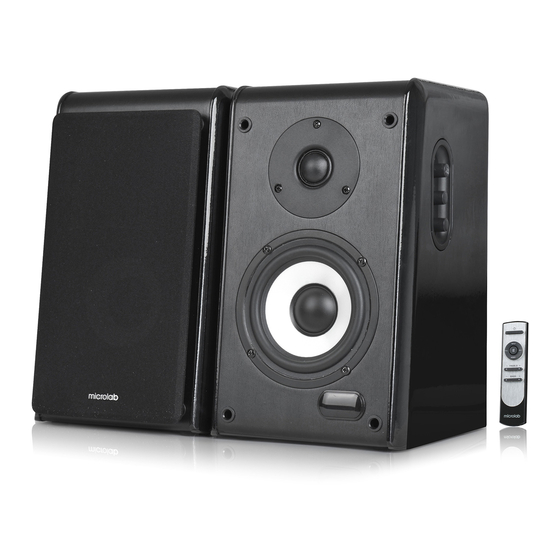
SOLO11
User Manual
Advertisement

Related Manuals for Microlab SOLO11


Summary of Contents for Microlab SOLO11
-
Page 1: User Manual
Slight variations and differences might appear between the printed photos and actual product due to Prior to initial use, please read the manual carefully product enhancement. © 2017 Microlab Electronics Co., Ltd. All rights reserved. - Page 2 Caution: To reduce the risk of electric shock, do not dismantle the product and do not expose the apparatus to rain or moisture. No user-serviceable parts inside. Refer servicing to qualified personnel only. Explanation of Graphical Symbols: The lightning flash within an equilateral triangle is intended to alert you to the presence of uninsulated dangerous voltage within the product's enclosure that may be of sufficient magnitude to constitute an electric shock to a person or persons.
-
Page 3: Packing List
19. Servicing - Do not attempt to service this product yourself, as opening or removing covers may expose you to Illustrations dangerous voltage or other hazards. Refer all servicing to qualified service personnel. 20. Please remove the power plug form the main power source or wall power source when not in use. When plugged in to a power source, the system is in standby mode, so the power is not entirely cut off. - Page 4 Connections and Operations Technical Specification 1. Figure illustrates 3.5mm to 2RCA connection. Turn on the power switch on the rear panel, default to AUX mode Amplifier with “AU” showed on the LED screen. Connect the audio cable via “AUX” port and start the playback. Output power, RMS 100 Watt RMS Power distribution, Watt...
- Page 5 This device complies with part 15 of the FCC Rules. Operation is subject to the following two conditions: (1) This device may not cause harmful interference, and (2) this device must accept any interference received, including interference that may cause undesired operation.
Need help?
Do you have a question about the SOLO11 and is the answer not in the manual?
Questions and answers