Table of Contents
Advertisement
Quick Links
Advertisement
Table of Contents

Related Manuals for Rotem communicator

Summary of Contents for Rotem communicator
- Page 1 Communicator User’s Manual...
- Page 2 In no event will ROTEM be liable to user or any third party for any direct, indirect, special, consequential or incidental damages, including but not limited to any damage...
- Page 3 4.2.3 Send SMS ..................23 5. Address Book ..................23 5.1 Contact Group ..................23 5.2 Options .....................24 6. Event Viewer ..................24 6.1 Application ..................24 6.2 Security.....................24 6.3 System....................25 7. Alarm ......................25 7.1 Network.....................25 7.1.1 Reset..................25 7.2 Communicator ..................26 Page 2 of 82 Revision No.: 1.5...
- Page 4 9) FLOW CHART OF VOICE DIAL OUT PROCESS.........44 10) SPECIFICATION ....................46 11) INSTALLATION....................47 11.1 Network Connection ................53 Connecting the External Connection box to Rotem's controllers using RS- 232 Card ....................53 Approximate Distances & Baud rate ...........54 Page 3 of 82...
- Page 5 Connecting the External Connection box to Rotem's controllers using RS- 485 Card ....................55 Approximate Distances & Baud rate ...........56 11.2 RF Network Connection ..............57 Option A with Platinum Plus RF (RCLP-RF) ...........57 Option B with Platinum Plus RF Remote ..........58 11.3 Routing Considerations ..............59...
- Page 6 Fig. 39: 'Network' menu screenshot..................25 Fig. 40: Reset screenshot....................... 26 Fig. 41: Reset screenshot after clicking on '?' key..............26 Fig. 42: 'Communicator' menu screenshot................26 Fig. 43: 'Reset Alarm' option screenshot ................27 Fig. 44: 'Alarm Options' features screenshot................. 27 Fig.
- Page 7 Fig. 94: Software Installation screenshot – part 2 ..............73 Fig. 95: Pre-installer screenshot .................... 74 Fig. 96: Hardware Wizard USB Communicator screenshot – part 1........74 Fig. 97: Hardware Installation screenshot ................75 Fig. 98: Hardware Wizard USB Communicator screenshot – part 2........75 Fig.
-
Page 8: User's Profile
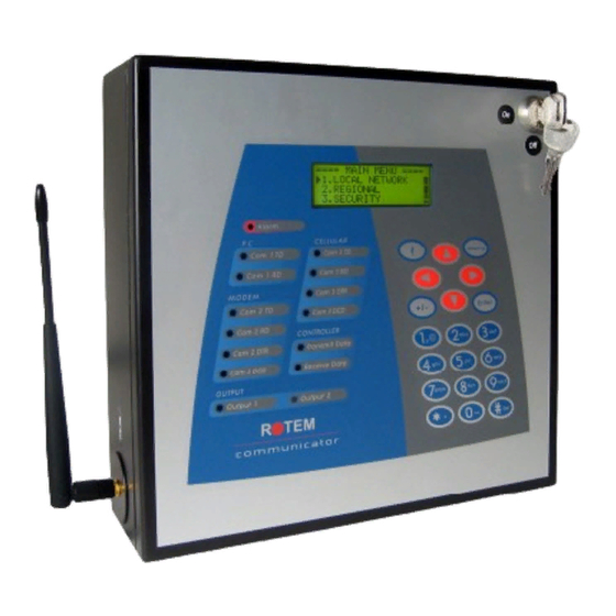
1.1 Description ROTEM Communicator is a device for alarm purposes and central communication systems. The Communicator has a user friendly interface with an alfa-numeric keypad, 20 character X 4 line LCD and indicative LED. 1.2 Main Features 1. Supports several communication sources and can link to any / all ROTEM controllers simultaneously. -
Page 9: User Interface
3) User Interface 1. Front Panel Fig. 1: Front Panel Available Keys Every item is explained according to its' number seen in Fig. 1. 1. Main menu screen. 2. Alarm LED – is activated when one or more alarm conditions are detected. The LED is turned off after doing 'Reset' and by that is acknowledged. - Page 10 15. This key erases typing mistakes. It also enables the ‘Cold Start’ function when held at power on (see Table 1 for further explanation). 2. Hot Keys The Communicator incorporates keys enable quick access information of different varieties (see Table 1). Page 9 of 82...
-
Page 11: Table 1: Hot Keys Summary
Initial Setup chapter). Cold Start 1. Disconnect the This procedure resets the communicator by communicator to the original switching the battery off. factory settings. It should be performed after replacing a 2. Turn power on while software version, either when... -
Page 12: Fig. 2: Example Of Using Hot Key '0
Fig. 2: Example of using Hot Key 0 Note that the squares (see Fig. 2) describe the houses do not have to be sequential. The squares can be one of the following: • Empty squares represent non-identified controllers. • Filled squares represent identified controllers. •... - Page 13 Fig. 3: Communicator's menu structure Page 12 of 82 Revision No.: 1.5...
-
Page 14: I) Initial Setup
1. Hardware Profile Go to Menu 9.1 (see Fig. 3) that defines the Hardware Profile and check whether the Communicator recognizes the hardware. If the communicator did not recognize all of the connected hardware, please refer to Appendix A. 2. Local Network Setup After making sure the Communicator's hardware is ok adapt the Communicator to Rotem controllers by either hard wired 485/RS232 or RF. -
Page 15: Ii) Advanced Settings
II) Advanced Settings Fig. 4 – 6 demonstrate the available options the main menu offers. Fig. 4: Main menu screenshot – part 1 Fig. 5: Main menu screenshot – part 2 Fig. 6: Main menu screenshot – part 3 1. Local Network Fig. -
Page 16: Controller Port
1.3 Serial Port The serial port (see Fig. 11) connects between the Communicator and the PC software. The baud rate set must be identical to the one set on the PC communication software in order to establish communication. -
Page 17: Test
1.4 Test Fig. 12: Modem menu screenshot This menu helps you test communication between Primery controllers and the communicator. Each controller is named by number, allowing the Communicator to identify and test the connection with it (see Fig. 12). 1.4.1 RS232/RS485 Fig. -
Page 18: Network List
2. Regional Setting Fig. 17: Regional Setting menu screenshot The main purpose of this option is to adjust the communicator to the local phone system, time and date (see Fig. 17). 3. Security Use the security feature to protect your Communicator. -
Page 19: Modem
Fig. 18: Security option screenshot Type password; • Retype for conformation and verify by selecting 'YES' (see Fig. 18). The system locks down automatically after 5 minutes. • In order to perform an instant lockdown press key number '9' (from the main screen). -
Page 20: Setup
Each “,” will represent the number of seconds in delay between the phone number and the next browsing number. d) Input Gain: For factory use only. If your communicator is unable to connect your voice dial in phone line, consult your local dealer regarding this feature. -
Page 21: Pager (Send Page)
This screen is meant to be used in order to increase transfer rate between the communicator and a remote modem. The communicator can compress data and send it faster. Their value can be changed by using the '+/-' key. The following features are... -
Page 22: Test (Send Page)
4.1.3 Dial Out Use this menu to verify the proper connection of the line to the communicator (see Fig. 28). • Dial your number and answer the phone. Test text over the phone is heard and the screen will display the message 'OK'. -
Page 23: Phone Line
4.1.4 Phone Line View the phone line voltage (see Fig. 29). Fig. 29: Phone Line option selection screenshot 4.2 GSM Modem Fig. 30 demonstrates 'GSM Modem' menu which is selected by option 4.2 (see Fig. Fig. 30: GSM Modem menu screenshot 4.2.1 Setup Fig. -
Page 24: Send Sms
Use this option to test the SMS service (see Fig. 33). • Insert a cellular phone number and press 'ENTER'. • The Communicator will send a following test SMS message: "The communicator is ready to send you alerts using SMS". -
Page 25: Options
5.2 Options Fig. 35: Options menu screenshot Fig. 35 reveals to 'Options' menu. This menu contains the following selections: 1. 'Call Out Delay': The time between activation of an alarm and the beginning of the dialout sequence. 2. 'In Between Call': The delay between each contact in the dialout sequence. This gives the requiered time to reply and acknowldegde the alarm. -
Page 26: System
6.3 System The system (History) view shows the date, time and code. This serves as an error handling (see Fig. 38). Fig. 38: System Event option screenshot 7. Alarm Go to the 'Alarm' menu (menu 7, see Fig. 3) to configure alarm options, reset and test the alarm system (see Fig. -
Page 27: Communicator
This menu is available if there is an active alarm (see Fig. 44). Note that the Reset is meant only to the communicator's alarm. Fig. 44 represents "low battery" mode. Note the following; an alarm has occurred and reset has been chosen. The system goes to a delay mode where the alarm won't be back till 12:00 AM of the next day, unless 'enable' to the alarm has been set. -
Page 28: Options
This section includes a history menu of all of the activated alarms (see Fig. 46). Note that this history information relates to the communicator only. The history itself will not appear on the net, for example, when suddenly there is no electricity. In this case it will be seen on the communicator's history, not on the net itself. -
Page 29: Accessories
Fig. 48 presents 'Digital Input' menu selection. 8.1.1 Setup The communicator supports 8 dry contact digital input card that can be programmed as a normally open / close dry contact input. These inputs can be connected to a wide variety of sensors such as generator operation, magnetic door or window, thermostat etc. -
Page 30: Test
This change triggers the alarm and the message “door opened” is sent to all addresses programmed in Alarm/Options/Addresses. 8.1.2 Test Fig. 50: Test selection screenshot This screen enables testing of digital inputs plugged into the system (see Fig. 50). Blank Squares represent open input and Full Squares represent a closed one. If you connect a device to one of the inputs and it remains blank, it means a problem exists. -
Page 31: Test
Fig. 55: Memory Restore Point selection screenshot This feature can help you restore previous software settings according to a specific restore point. If restore point was not created yet, the communicator will inform you that there is no restore point. -
Page 32: System
Fig. 57: System menu screenshot Fig. 57 presents 'System' menu. 9.1 Hardware Profile Fig. 58: Hardware Profile screenshot See Preliminary Setup section. 9.2 Voice Use this menu to adjust the Communicator voice settings (see Fig. 59). Page 31 of 82 Revision No.: 1.5... -
Page 33: Battery
Fig. 59: Voice Setting menu screenshot The following explains the variables: Volume: Use the left/right arrow keys to lower/amplify the volume. Speed: Use the left/right arrow keys to adjust the voice message speed. Test: Press 'ENTER' to hear a test voice message. Note that the speed and volume cannot be adjusted during the test. -
Page 34: Options
9.3.2 Options Fig. 62: Power Options screenshot This option allows the user to set an alarm delay time in seconds (see Fig. 62) for power failure alarm only. This alarm does not reset without acknowledgment. Otherwise, it remains in the system forever. Page 33 of 82 Revision No.: 1.5... -
Page 35: Test
9.4 Test Fig. 63: System Test menu screenshot 9.4.1 RS232/RS485 Fig. 64: Communication option screenshot In order to test comminication, insert the controller’s number and press 'ENTER' to start / stop the test procedure (see Fig. 64). 'Tx' means “Transmited data” and 'Rx' means “Received data”. -
Page 36: Pager
9.4.4 Dial Out Use this menu to verify the proper connection of the line to the communicator (see Fig. 69). • Dial your number and answer the phone. Test text over the phone is heard and the screen will display the message 'OK'. -
Page 37: Phone Line
Fig. 69: Dial Out option selection Screenshot 9.4.5 Phone Line View the phone line voltage (see Fig. 70). Fig. 70: Phone Line option selection screenshot 9.4.6 GSM Signal Fig. 71: Signal Strength option screenshot Select this option in order to make sure the signal is strong enough (see Fig. 71). Moreover, make sure both the cellular modem and the cellular provider are recognized. -
Page 38: Alarm Relay
Use this option to test the SMS service (see Fig. 72). • Insert a cellular phone number and press 'ENTER'. The Communicator will send a following test SMS message: "The communicator is ready to send you alerts using SMS". 9.4.8 Alarm Relay Fig. -
Page 39: Eeprom
9.4.11 EEPROM Fig. 76: EEPRO Test screenshot This screen tests that the EPROM operates in order (Fig. 76). 9.4.12 Voice Fig. 77: Voice Setting menu screenshot The following explains the variables: Volume: Use the left/right arrow keys to lower/amplify the volume. Speed: Use the left/right arrow keys to adjust the voice message speed. -
Page 40: Keyboard
9.4.14 Keyboard Fig. 79: Keyboard screenshot This screen tests if clicking on a specific number matches the number displayed on the screen (Fig. 79). Page 39 of 82 Revision No.: 1.5... -
Page 41: Sending Test Message Commands And Status Requests From / To The Communicator
5) Sending Test Message Commands and Status Requests from / to the Communicator It is possible to send an SMS from a mobile phone to the Communicator device. It is done by using the following SMS message formats: • Siren Reset: If siren reset is requested, the following SMS message should be sent: '!RX' >... -
Page 42: Network Setup
32 controllers. The parameter 'Primary' is set to be the number of controllers defined in the communicator network. This parameter is divided to 2 branches; o Lower branch – 1 to 32 controllers o Upper branch –... -
Page 43: Voice – Dialing To The Communicator
7) Voice – Dialing to the communicator It is possible to dial the communicator in order to receive information regarding the alarms. In order to enable this option, the parameter 'Dial in' (see menu 4.1.1) needs to be set to 'Yes' (see Fig. 82). -
Page 44: Voice Dial Out To Contact List
8) Voice Dial Out to Contact List • The Communicator dials to the contact list as defined. If no contact list exists, the communicator does not dial. • Once the controller alarm is triggered, a greeting voice message is being read aloud: "Good <Morning/Afternoon/Evening> <poultry farmer's name>, <farm name>... -
Page 45: Flow Chart Of Voice Dial Out Process
9) Flow chart of Voice Dial out Process Page 44 of 82 Revision No.: 1.5... - Page 46 Page 45 of 82 Revision No.: 1.5...
-
Page 47: Specification
10) Specification Power supply Mains Voltage Single Phase 230 VAC (Outside the US & CANADA) 115 VAC 0.5A (US & CANADA) Mains Frequency 50/60HZ Maximum Power Consumption Main Fuse Main Fuse (12V) 125/250V 100mA T Main Fuse (Switching P.S)) 125/250V 2A T Connection Box peripheral Digital inputs... -
Page 48: Installation
Attention! • Do not keep the battery connected without electricity. • Use an exclusive phone line for the Communicator. (Do not share a line for the Communicator with another phone) Note: Sometimes using a phone line via private switchboard might cause problems, therefore it is recommended to use a different line to the communicator. - Page 49 Fig. 85: Functional block diagram Page 48 of 82 Revision No.: 1.5...
- Page 50 Fig. 86: Wiring Diagram using RF communication card Page 49 of 82 Revision No.: 1.5...
- Page 51 : Connect the Local PC either by using COM Port cable or by using the USB cable Page 50 of 82 Revision No.: 1.5...
- Page 52 Communicator RF Antenna device RF Antenna Extension COAX Cable Fig. 87: Wiring Diagram using RF communication card – external view Page 51 of 82 Revision No.: 1.5...
- Page 53 External Connection Box Digital Inputs …….. Refer to Relay 1 Relay 2 Network General Purpose Connection …….. Dry Contact Relays In 1 In 8 section Must be connected to Safety Ground Buttery for lightning protection Siren Fig. 88: External connection box wiring diagram Page 52 of 82 Revision No.: 1.5...
-
Page 54: Network Connection
11.1 Network Connection Connecting the External Connection box to Rotem's controllers using RS-232 Card Fig. 89: Connection with RS-232 card wiring diagram The cable between the external connection box and the controllers should be a 3 Wire Shielded Cable (at leasr 22AWG). -
Page 55: Approximate Distances & Baud Rate
The shield should be connected to the earth (Safety Ground). The shield (safety ground) should be connected only on one side! Approximate Distances & Baud rate For one controller: ~2000 meters (~6500 feet) - 9600 Baud ~2500 meters (~8200 feet) - 4800 Baud ~3000 meters (~9800 feet) - 2400 Baud For 10 controllers: ~1200 meter (~4000 feet) - 9600 Baud... -
Page 56: Card
Connecting the External Connection box to Rotem's controllers using RS-485 Card Fig. 90: Connection with RS-485 card wiring diagram The cable between the external connection box and the controllers should be a 2-wire shielded cable. This cable is daisy-chained to all controllers and to exrternal connection box as... -
Page 57: Approximate Distances & Baud Rate
Approximate Distances & Baud rate For one controller: ~2000 meters (~6500 feet) - 9600 Baud ~2500 meters (~8200 feet) - 4800 Baud ~3000 meters (~9800 feet) - 2400 Baud For 10 controllers: ~1200 meter (~4000 feet) - 9600 Baud ~1800 meter (~6000 feet) - 4800 Baud ~2400 meter (~7870 feet) - 2400 Baud Baud rate is dependent on cable length and number of controllers. -
Page 58: Rf Network Connection
11.2 RF Network Connection Option A with Platinum Plus RF (RCLP-RF) Page 57 of 82 Revision No.: 1.5... -
Page 59: Option B With Platinum Plus Rf Remote
Option B with Platinum Plus RF Remote SITE OFFICE Away Local (Non RCLP-232/485 RCLP-232/485 Priority ………... channel) Local PC Page 58 of 82 Revision No.: 1.5... -
Page 60: Routing Considerations
11.3 Routing Considerations There are two common routing methods for running the communications connections: Daisy Chain (recommended) and Star connection (not recommended). The following are two recommended alternatives Daisy-Chain Star Daisy & Connection Combination Connection STAR Page 59 of 82 Revision No.: 1.5... -
Page 61: Appendix A: Troubleshooting
Reconnect the power and switch the battery ON so that the unit will rescan the hardware. If this does not help, open the Communicator and check that the device is installed properly. If still not operating, replace the device. - Page 62 Problem Description 'Lost unit number' alarm o Troubleshooting 1. Make sure the Communicator is connected to an electric power supply. 2. Press hot key 0 and check if either some of the controllers are missing (blank squares), or all of them.
-
Page 63: Cellular Modem
Cellular Modem Problem Description Problem in signal strength Troubleshooting The modem has to be placed in a way that ensures sufficient signal strength. To improve signal strength, the antenna can be moved to another position. Signal strength may depend on how close the modem is to a radio base station. You must ensure that the location, at which you intend to use the modem, is within the network coverage area. -
Page 64: Voice Card
4. If nothing of the above helps, contact your dealer. Alarm Problem Description Receiving no messages from the communicator Troubleshooting 1. Check if the active alarms are not defined in disable state. 2. Go over the contact group and make sure the users are not set to 'idle' and that the group is written correctly. -
Page 65: Line Modem
40V (normally it is 48V or more). If it is above 40V, connect regular phone for testing. If the line does not operate, the line is wrong. If the line is ok, do power cycle (by turning the device off and than on) to the communicator. Wait a while until the communicator recovers. -
Page 66: Appendix B: Rf
13) Appendix B: RF In order to configure RF communication you need to set the baud rate and channel on both sides of the RF. 1. Configuration (DIP 1): In order to configure new parameters: move DIP switch to 'on' state, arrange all parameters according to the following section, press reset, wait until LED RX is off. -
Page 67: Table 4: Rf Performance Range
Dip Switch configuration procedure: Rearrange DIP switches 2-8 according to following procedure: a) Move DIP switch 1 (config) to 'on' position. b) Make any necessary changes in the DIP switch position. c) Press Reset. d) RX LED should be lit for 4-12 seconds. e) Return DIP switch 1 to off position. -
Page 68: Table 5: Potential Signal Strength Loss Due To Antenna Cable Length
other heavy construction will inhibit signals more than light obstacles such as a few trees or a simple post. When trying to increase the range, several factors including antenna height, frequency, antenna type and power output when all should be considered. -
Page 69: Appendix C: Alarm Code Numbers
14) Appendix C: Alarm Code Numbers CODE No. DISCRIPTION SENSORS (1 – 80) Low Temperature High Temperature Sensor # Low Temperature Sensor # High Temperature Emergency # Low Temperature Emergency # High Temperature Circuit Breaker High Temperature Egg Room Low Temperature Egg Room High Temperature Temperature Sensor # Out of Range HUMIDITY (21 –... - Page 70 CODE No. DISCRIPTION Low Feed At Feed Bin # Feed Container Overflow Feed Shortage WATER (101 – 110) Water Overflow Water Shortage Water # Leak High Flow Valve # Low Flow Valve # No Flow Valve # Stop System Flow Alarm Negative Flow HARDWARE (111 –...
- Page 71 CODE No. DISCRIPTION Scale Card # Fail Alarm Card Fail Remote output key fail ADDITIONAL HARDWARE (151 – 160) Error In Remote Unit # Scale Card Plug fail Vent # fail Curtain # Fail Error in Extension box # Generator POWER / BATTERY (161 –...
- Page 72 CODE No. DISCRIPTION Check All Settings Egg Sensor Conflict Out Sensor Conflict OTHER ALARMS (231 – 240) Alarm Test USER DEFINED SECTION (240 – 254) Auxiliary Alarm (Dig Input) MULTIPLE ALARM INDICATOR Page 71 of 82 Revision No.: 1.5...
-
Page 73: Appendix D: Usb Driver Installation
2.1) Driver Installation using Windows XP Follow the steps to install Windows XP VCOM driver: 1. Preinstall the USB drivers delivered with communicator from CDROM. - execute 'Preinstall.exe' file and follow screen instructions (Fig. 93-96); 1.1 Fig. 93 is displayed. Click the 'Install' button. -
Page 74: Fig. 94: Software Installation Screenshot – Part 2
1.2 Fig. 94 is seen. Click the 'Continue Anyway' button. Fig. 94: Software Installation screenshot – part 1 1.3 Fig. 95 is shown. Click the 'Continue Anyway' button. Fig. 95: Software Installation screenshot – part 2 1.4 Fig. 96 is displayed. Click the 'OK' button. Page 73 of 82 Revision No.: 1.5... - Page 75 2. Connect the USB cable between the host computer and the communicator. Connect the communicator to its plug and finally connect the USB cable to the communicator. 3. Windows opens a “Found New Hardware Wizard” balloon message in the right bottom of the screen.
- Page 76 Fig. 98: Hardware Installation screenshot 6. Fig. 99 is shown. Press Finish to finish installing the "USB Device". Fig. 99: Hardware Wizard USB Communicator screenshot – part 2 7. Windows opens a “Found New Hardware Wizard” balloon message in the right bottom of the screen.
- Page 77 Fig. 100: Hardware Wizard Communicator screenshot – part 1 9. Fig. 101 is seen. Click the 'Continue Anyway' key. If Windows asks about a driver that is not signed as Windows XP driver, select 'Install Anyway'. Fig. 101: Hardware Installation screenshot 10.
-
Page 78: Driver Installation Using Windows 2000
2.2) Driver Installation using Windows 2000 Follow these steps to install the Windows 2000 VCOM driver: 1. Connect the USB cable between the host computer and the communicator. 2. Windows will open a “Found New Hardware Wizard” window. Press the 'Next' button to continue. -
Page 79: Virtual Com Port Driver Installation Windows 98 Se
2.3) Virtual COM Port Driver Installation Windows 98 SE Follow these steps to install the Windows 98 VCOM driver: 1. Connect the USB cable between the host computer and the communicator. 2. Windows will open a “Found New Hardware Wizard” window. Press the 'Next' button to continue. -
Page 80: Appendix E: Ordering Information
16) Appendix E: Ordering Information The basic unit included the attached parts list Basic unit Part #: P-COMM-V1 Part # Description C-COMM-BOX COMMUNICATOR CONNECTION BOX CARD C-COMM-CPU COMMUNICATOR CPU CARD C-COMM-KBD COMMUNICATOR KEYBOARD CARD W/O DISPLAY C-COMM-PS-V1 COMMUNICATOR POWER SUPPLY CARD 115Volt... - Page 81 There are three part numbers for kits that include the following parts: Part # Description P-COMM-232-S-V1 COMMUNICATOR SET 115Volt(LM,RPLP,RS232) Communicator basic unit + Line Modem, RPLP-1, and RS-232 Card. P-COMM-RF-S-V1 COMMUNICATOR SET 115Volt(LM,RPLP,RF,C15) Communicator basic unit + Line Modem, RPLP-1, and RF Card with 15 meter (50 feed) cable and Antenna.
- Page 82 C-COMM-RF10-9-M COMMUNICATOR RF 100mW 900MHz MODULE ONLY P-COMM-RF10-9-S Assembled COMMUNICATOR RF 100mW 900MHz C-COMM-RF10-9-S Spare COMMUNICATOR RF 100mW 900MHz SET A-RF-AN-2-C6-58 RF 6M RG58 CABLE &CLIP FOR 2dBi ANTENNA A-RF-AN-2-C15-58 RF 15M RG58 CABLE &CLIP FOR 2dBi ANTENNA A-RF-AN-2-C23-58 RF 23M RG58 CABLE &CLIP FOR 2dBi ANTENNA...
- Page 83 Part # Description A-COMM-BOX Communicator Connection box A-COMM-C-CB Cable for connection box A-COMM-C-PC Serial DB9 cable for PC A-COMM-C-USB USB cable for PC A-COMM-LM-C COMMUNICATOR LINE MODEM TELEPHONE CABLE Page 82 of 82 Revision No.: 1.5...
- Page 84 ROTEM Computerized Controllers Ltd. 972-3-920-6200 FAX: 972-3-924-9834 ISRAEL Web site- www.rotem.com Email- rotem@rotem.com...
Need help?
Do you have a question about the communicator and is the answer not in the manual?
Questions and answers