Table of Contents
Advertisement
Advertisement
Table of Contents

Related Manuals for Rotem P-COMM-V1

Summary of Contents for Rotem P-COMM-V1
- Page 1 Communicator User & Installation Manual P/N: 110048...
- Page 2 In no event will ROTEM be liable to a user or any third party for any direct, indirect, special, consequential or incidental damages, including but not limited to any damage or injury to...
- Page 3 Sometimes using a phone line via private switchboard might interfere with communication. Rotem recommends using a different line to the Communicator. CAUTION As a backup to the Communicator, Rotem recommends installing an Emergency Light and Siren system. If the Communicator is unable to transmit alarms via SMS or the telephone (for example there is a complete power failure), the Emergency Light and Siren system sounds an alarm.
-
Page 4: Table Of Contents
Table of Contents Front Matter ....................7 ......................Introduction ......................Conventions ....................Contact Information ..................Document Information Precautions ..................... 8 Introduction to the Rotem Communicator ........... 9 ....................... Main Features ................Choosing Communication Cards ....................... User Interface ....................3.3.1 Front Panel .................... - Page 5 ................6.1.3 Displaying the Controllers ................ 6.1.4 Listing the Network Devices ..................... RS-232 Connection .............. 6.2.1 Setting up the RS-232 Connection ..........6.2.2 RS-232 Approximate Distances and Baud Rate ..................... RS-485 Connection .............. 6.3.1 Setting up the RS-485 Connection ..........6.3.2 RS-485 Approximate Distances &...
- Page 6 ..........11.1.2 Connecting the Unit to External Components ..................11.1.3 Additional Details ................11.1.4 USB Driver Installation ................. 11.2 Completing the Installation ........11.2.1 Configuring the Communication to Outside Devices ............... 11.2.2 Setting Up an Internet Connection ............11.2.3 Setting Up a Network Using RotemNet 12 Troubleshooting ...................
-
Page 7: Front Matter
Rotem will not accept responsibility for damage resulting from the use of this manual. Rotem also reserves the right to make changes and improvements to its products and/or the associated documentation without prior notice. -
Page 8: Precautions
2 PRECAUTIONS Observe the following precautions when using your unit. • Always connect temperature and sensor shields to earth ground. Avoid mixing high voltage wiring with sensor and low voltage wiring. • Keep the controller as far as possible from heavy contactor boxes and other sources of electrical interference. -
Page 9: Introduction To The Rotem Communicator
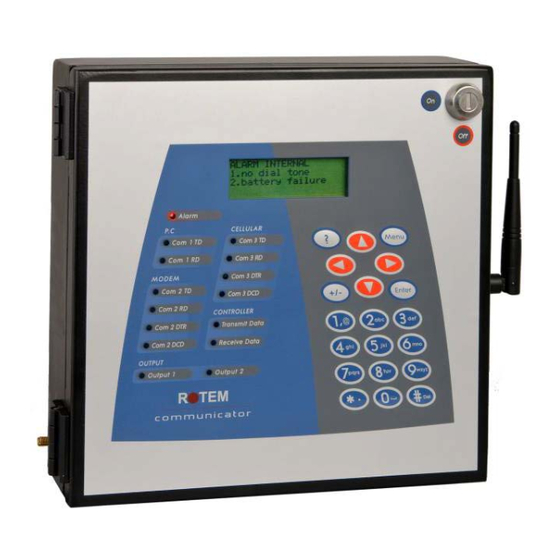
3 INTRODUCTION TO THE ROTEM COMMUNICATOR ROTEM Communicator, Version 3.05 is a state-of-the-art alarm and communication center used by famers to monitor and control their Rotem Controllers and accessories. The Communicator has a user friendly interface with an alfa-numeric keypad, 20 character by 4 line LCD and indicative LED. -
Page 10: Front Panel
3.3.1 Front Panel Function PC Com 1 TD/RD PC is transmitting/receiving data to/from the Communicator Modem Com 2 TD/RD Modem is transmitting and receiving data Modem Com 2 DTR/DCD Data transmitter ready/Data carrier detect (technician only) Cellular Com 3 TD/RD Cellular modem is transmitting and receiving data Controller Transmit Data Receive Data Controller relays are transmitting and receiving data... -
Page 11: Menu Tree
3.3.2 Menu Tree 1. FARM NAME 2. ADDRESS BOOK 3. STATUS REPORT MY FARM 3. CONTROLLERS 4. PASSWORD 5. TIME & DATE 1. RESET 2. TEST SCHEDULE ALARM 3. DISABLED ALARMS 4. OPTIONS SIGNAL 1. ALARM 1. BATTERY STRENGTH HISTORY 2. -
Page 12: Initial Configuration
Before installing a SIM card, disable the PIN code (if the card has this code). Communicator text functions are disabled if the SIM card has a PIN code. 4.1 Communication Recommendations Rotem strongly recommends: • enabling both the telephony and SMS functions to transmit alarms (via voice and SMS) •... -
Page 13: Setting The Test Schedule
DAY: Define the day of the week to perform the alarm test (this is required only when FREQUENCY=WEEKLY) WARNING! ROTEM STRONGLY RECOMMENDS REGULAR TESTING OF THE ALARMS., DO NOT DISABLE THIS TEST UNLESS THE HOUSE IS EMPTY! 4.3 Setting the Language 1. -
Page 14: Identifying The Controllers
Priority of contacts is defined by the user number (1-16). Top priority contacts should be entered into the address book first. CAUTION Rotem strongly recommends entering contact information immediately. Contact list fields: •... -
Page 15: Phone Number Structure
testing). • MOBILE NUMBER: Enter the mobile number for the text message service. • PAGER: Enter the pager phone number. Refer to Pager Setup, page 20 for options and testing. In addition, refer to Configuring the Dial Delay, page 21. NOTE: When entering the above numbers, refer to Phone Number Structure, page 15. -
Page 16: Communicator To User Functions
5 COMMUNICATOR TO USER FUNCTIONS The following sections detail how to use the: • Voice, page 16 • Pager, page 20 • Text, page 21 • Common Functions, page 25 5.1 Voice Functions The following sections detail Communicator’s basic and advanced Voice functions. •... -
Page 17: Advanced Voice Functions
1. Call the Communicator phone number. 2. When prompted, select Status report. 5.1.2 Advanced Voice Functions This section details Communicator’s advanced Voice functions. CAUTION Rotem recommends that only trained, authorized technicians configure these functions. • Configuring the Telephone Modem, page 18 •... - Page 18 5.1.2.1 Configuring the Telephone Modem • Select SYSTEM > Advanced Setup > Line Modem. LINE MODEM AUTO ANSWER LINE TEST DIAL DELAY ( , ) INPUT GAIN VOICE DIAL-IN This screen defines the line modem specifications. • AUTO ANSWER: Number of rings before the Communicator automatically answers a dialed-in call.
-
Page 19: Responding To An Audio Alarm Message
5.1.3 Responding to an Audio Alarm Message The Voice Dial Out service transmits audio alarm message, via telephony, from Communicator to the contacts entered in the Address Book (page 14). This section details the procedure to follow when an audio alarm is received. NOTE: This service is provided by the Communicator ONLY if the Address book is properly defined with contacts and the "VOICE"... -
Page 20: Pager Functions
5.2 Pager Functions The following sections detail the Communicator’s basic and advanced Pager functions. • Basic Pager Functions, page 20 • Advanced Pager Functions, page 21 5.2.1 Basic Pager Functions This section details the basic Pager functions. • Pager Setup •... -
Page 21: Advanced Pager Functions
5.2.2 Advanced Pager Functions The following section details the advanced Pager functions. 5.2.2.1 Configuring the Dial Delay • Go to SYSTEM > Advanced Setup > Line Modem. When dialing a pager service, some services require additional tone menu browsing (interactive voice response). -
Page 22: Status Report
5.3.1.3 Status Report Upon a user request, Communicator sends a status report on basic house functions and animal statistics. The report includes the following specifications: • Target Temp • Average Temp • Vent Level • Vent Mode (minimum ventilation, natural, tunnel) •... -
Page 23: Advanced Text Functions
5.3.2 Advanced Text Functions The following sections detail the advanced Text functions. • Defining Who Can Text Communicator • Configuring an SMS Ringtone 5.3.2.1 Defining Who Can Text Communicator 1. Go to SYSTEM > Advanced Setup > GSM. CELLULAR MODEM TEXT FROM Addr. - Page 24 5.3.3.1 Resetting the Siren NOTE: After typing the text message, press the 'Send' button to send it to the Communicator. In the procedures below, the highlighted text shows the SMS text to be sent. • Resetting the Siren of One House !RX >...
-
Page 25: Common Functions
5.4 Common Functions The following sections detail the technician tools. • Go to SYSTEM > Technician Tools. TECHNICAL TOOLS TEST MESSAGE OPTIONS HYPER TERMINAL MONITOR This menu provides testing tools used by an authorized technician only. • Test • Message Options •... -
Page 26: Communicator To Controller Functions
(recommended) and Star connection (not recommended). Figure 1: Daisy Chain Figure 2: Daisy and Star Combination Figure 3: Star Routing NOTE: Employing a Rotem RS-232 or RS-485 Repeater enables Star routing. Refer to the relevant manuals for details. Communicator | 3.05... -
Page 27: Configuring The Channel Settings
6.1.2 Configuring the Channel Settings • Go to SYSTEM > Advanced Setup > RF/Wired Network. SERIAL PORT BAUD RATE 9600 CHAN(6-7-8) ADDR(4-5) This menu defines data rate and settings between the Communicator and its subunits. NOTE: This menu does not define the data rates to the PC. •... -
Page 28: Displaying The Controllers
Square 1 Square 2 Address 2 Address 3 6.1.3 Displaying the Controllers • Press 01 16 17 32 33 48 49 64 01 16 This screen displays all the controllers that are connected to the system. ... -
Page 29: Setting Up The Rs-232 Connection
6.2.1 Setting up the RS-232 Connection 1: Controller communicator card 2: Next house 3: Connect one end of the cable's shield only. Each controller should be chain connected to the same wire, resulting in a long ground cable without ground loop. ... -
Page 30: Rs-232 Approximate Distances And Baud Rate
CAUTION Connect the shield (safety ground) only on one side! 6.2.2 RS-232 Approximate Distances and Baud Rate • For one controller: ~2000 meters (~6500 feet): 9600 Baud ~2500 meters (~8200 feet): 4800 Baud ~3000 meters (~9800 feet): 2400 Baud • For 10 controllers: ~1200 meter (~4000 feet): 9600 Baud ~1800 meter (~6000 feet): 4800 Baud... - Page 31 1: Controller communicator card 2: Next house 3: To prevent ground loops, connect the shield wire at one end only 4: Communicator External Box Figure 5: Connecting the External Connection box to Controllers via RS-485 Cards •...
-
Page 32: Rs-485 Approximate Distances & Baud Rates
Figure 6: Connecting the External Connection box to Controllers via RS-ISO485 Cards • The cable between the external connection box and the controllers should be a two pair twisted shield cable. • This cable is daisy-chained to all controllers and to external connection box. pair: ... -
Page 33: Rf Connection
6.4 RF Connection The following sections detail how to set up an RF connection to the controllers. • Option A with Platinum RF (RCLP-RF) • Option B with Platinum RF Remote 6.4.1 Option A with Platinum RF (RCLP-RF) 6.4.2 Option B with Platinum RF Remote ... -
Page 34: Channel/Signal Tests
In existing installations, go to System > Save/Res Setting > Restore and run the function. Communicator automatically configures the base unit's settings; there is no need to configure this unit's DIP switches. CAUTION Resetting the Communicator or disconnecting the power only is insufficient! 6. -
Page 35: Communicator To Pc Configuration
Make sure the modem you are connected to can read and decompress the received data. • DATA FLOW: This feature enables the hardware to vary the data transmission rate. CAUTION Rotem recommends that the user leave the Advanced menu items at their default settings. Communicator | 3.05... -
Page 36: Configuring The Dry Contact Card
8 CONFIGURING THE DRY CONTACT CARD The following section details how to set up the dry contact cards. Communicator supports an eight dry contact digital input card that can be programmed as a normally open / close dry contact input. These inputs can be connected to a wide variety of sensors such as generator operation, magnetic door or window, thermostat, etc. -
Page 37: Communicator Functions
9 COMMUNICATOR FUNCTIONS The following sections detail functions which relate to the Communicator hardware and software. • • Saving and Restoring System Settings, page 37 Viewing Relay Settings, page 38 • Test Functions, page 37 9.1 Saving and Restoring System Settings •... -
Page 38: Viewing Device Status
1 VOICE 2 LINE MODEM 3 CELLULAR View functionality status of all possible installed devices. 9.2.3 Viewing the Software and Hardware Version • Press http://www.rotem.com SOFTWARE 3.00r01-b HARDWARE 2.04 1.00 This screen displays the software and hardware version numbers. 9.3 Viewing Relay Settings... -
Page 39: Alarms
10 ALARMS This section details how to: • Configure advanced alarm settings. • View the history of alarms and events Basic Alarm functions are defined in the Initial Configuration, page 12. • Introduction to Alarms and Responses, page 39 • Event Codes, page 40 •... -
Page 40: Event Codes
10.2 Event Codes Table 1 lists the event codes sent in text messages. Table 3: Event Codes Event Code LCD Message "power off " "power on" "cold start" "error-01" "test running" 6, 7 , 9, 10, 11, 12, 16, 17 "fail"... -
Page 41: Disabling Alarms
10.3.2 Disabling Alarms • Go to ALARM > Disabled Alarms DISABLE ALARMS DISABLE ALARMS HOUSE DISABLE CODE MESSAGE 185 155 View disabled alarms and re-enable these alarms. NOTE: : Alarms are disabled until 12:00 PM the following day. • Scroll right to view message. •... -
Page 42: Defining The Internal Alarms
10.3.5 Defining the Internal Alarms • Go to ALARM > Options. Internal alarms are generated by the Communicator unit (external alarms are generated by the controllers). This menu defines: • DELAY (seconds): Define the waiting time before the communicator generates an internal message. -
Page 43: Displaying The User Events
Failure to test your pack regularly and change the pack as required can result in losses in the event of a general power failure! Rotem strongly recommends: • Checking the backup battery pack once a month (see the procedure below). - Page 44 Figure 8: Communicator Battery Packs, Version 3.1 Figure 9: Communicator Battery Packs, Version 2.3 The following two tests provide accurate data regarding the backup battery pack’s charge level. Rotem recommends performing both tests. If you need to replace the battery, order a Communicator Battery Pack (P/N: SP-COMM-BA).
-
Page 45: Dial-Up Test
10.5.1 Dial-Up Test • Unplug the unit. If the batteries are charged, Communicator sends an SMS/voice/pager alarm message to the numbers configured in the Address Book. The message should arrive within several minutes. If the batteries are not charged, Communicator does not send an alarm message. In addition, an alarm message appears on the screen. -
Page 46: Installation
11 INSTALLATION The following sections detail how to install the Communicator. CAUTION Rotem recommends that only an authorized technician install and configure the Communicator unit. • Hardware Installation, page 46 • Completing the Installation, page 50 11.1 Hardware Installation The following sections detail how to perform the Communicator’s physical setup. - Page 47 Figure 11: External Connection Box Connector and Internal Components (Sample) Board Version 3.1 (line and port cards not shown) NOTE: This version supports two sockets for communication adaptors. 2. Connect the ground cable to the dedicated ground terminal (Figure 12). Figure 12: Grounding Terminal (Version 3.1) CAUTION The Communicator must be grounded at all times! Communicator | 3.05...
-
Page 48: Connecting The Unit To External Components
3. Connect the local computer by via the PC Port or a USB cable. NOTE: If you use the USB drive, install the Rotem driver (refer to USB Driver Installation, page 49). 4. Connect the line and phone cables. 5. Connect the ethernet cable to ethernet access point; for example an ADSL modem/router (Version 3.1 only). -
Page 49: Additional Details
11.1.3 Additional Details • Table 2 details the communication card types. Table 4: Communication Card Types RS-232 Card RS-485 Card RF Card • Figure 13 illustrates how to wire the External Communication Box to a controller and an ELS system. Figure 13: External Communication Box Wiring Diagram with ELS 11.1.4 USB Driver Installation... -
Page 50: Completing The Installation
3. On the Ethernet cable port (Figure 11), verify that: • the green lights remains on • the yellow light blinks 4. Set the Communicator Internet settings. a. In a web browser, go to http://www.myrotem.net. b. In the Account Name field, type Rotem. Communicator | 3.05... - Page 51 Click Save. INTERNET DEVICE SN: 140011BD [SERVER] 80.179.187.139 Port: 1500 Name: Rotem Account: <Farm 1 Users: 03 The Internet connection is now configured. 6. In a web browser, go to http://www.myrotem.net and login using the name and password that you chose.
-
Page 52: Setting Up A Network Using Rotemnet
Figure 15 appears. Figure 15: Controller Data (Example) • Rotem recommends the following resolutions when viewing the web: PC: 1280/1024 Text size medium Laptop: 1024/768 Text size medium 11.2.3 Setting Up a Network Using RotemNet Accessing the Communicator or controllers via RotemNet enables local and remote management of your equipment. - Page 53 11.2.3.1 Local Network 1. Under Network Setup, select Local Network. 2. Select the required baud rate. NOTE: The selected baud rate must be the same as the rate selected in the Communicator. 3. Select the communication port. NOTE: If the connection is via the USB port, select Communicator. 4.
-
Page 54: Troubleshooting
12 TROUBLESHOOTING The following section details common troubleshooting procedures. • Hardware, page 54 • Communication to Controllers/PC, page 54 • Cellular Modem, page 56 • RF Communication, page 57 • Voice Card, page 58 • Alarm, page 59 • Line Modem, page 59 NOTE: Lists of part numbers and their descriptions are located in Ordering Information, page 63. - Page 55 5. Go over the number of controllers and make sure there is no conflict between the units (make sure that two units do not have the same configuration number). 6. If all above are OK: a) Check the wiring for 232/485 communication card. b) Check RF card signal strength (refer to Testing the Cellular Signal Strength, page 17).
-
Page 56: Cellular Modem
12.3 Cellular Modem Problem in signal strength Figure 16: Cell Modem Card Location Figure 17: Line Modem Card Location The modem has to be placed in a way that ensures sufficient signal strength. • To improve signal strength, the antenna can be moved to another position. Signal strength may depend on how close the modem is to a radio base station. -
Page 57: Rf Communication
4. If no signal exists: a) Check antenna connection. b) Check connection to the module (GSM). c) Check the wiring. If there is a problem, contact the dealer. Refer to the appropriate section in Appendix A: Replacing Communication Cards and Modems, page 68 for detailed instructions on exchanging the modem. -
Page 58: Voice Card
12.5 Voice Card Voice does not function Figure 19: Voice Card Location 1. Refer to Testing Voice, page 16 and perform a voice test. 2. Change the parameters as required (refer to Testing Voice Quality, page 16). NOTE: Do not forget to confirm by moving the cursor to the ‘TEST’ parameter and pressing 'ENTER'. 3. -
Page 59: Alarm
12.6 Alarm No messages are being received from the Communicator 1. Verify active alarms are not defined as disable state (refer to Setting the Test Schedule, page 12). 2. Go over the contact group, make sure the users are not set to 'idle' (refer to Adding Names to the Address Book, page 14) and that the contact information is entered correctly. -
Page 60: Specifications
13 SPECIFICATIONS Power Supply Mains Voltage Single Phase 230 VAC (outside the US & Canada) 115 VAC 0.5 A (US & Canada) Mains Frequency 50/60 Hz Maximum Power Consumption 40 W Main Fuses Main Fuse (12 V) 125/250 V, 100 mA T Main Fuse (Switching P.S.) 125/250 V, 2 A T Connection Box Peripherals... -
Page 61: Parts Catalog
14 PARTS CATALOG The following sections illustrate the components that come with the Communicator. • Standard Components, page 61 • Additional Components, page 62 • Ordering Information, page 63 • Compatibility Issues with the Communicator CPU, page 65 14.1 Standard Components The following components are included in every order. -
Page 62: Additional Components
14.2 Additional Components The following components are specific for each installation. P-COMM-RS485 P-COMM-RS232 P-COMM-LM-S Communicator RS-485 Card Communicator RS-232 Card Communicator Line Modem Set P-COMM-RF5-24-S P-COMM-RF232-S2 A-RF5-24-AN-D RF 2.4 GHz Directional Antenna Communicator RF 50 mW 2.4 Communicator RF & RS232 900 GHz Set MHz Set232 A-RF10-9-AN-D... -
Page 63: Ordering Information
14.3 Ordering Information The following tables list every Communicator component. The basic unit includes the following parts list. Table 5: Basic Unit Part Number: P-COMM-V1 Part # Description C-COMM-BOX Communicator Connection Box Card C-COMM-CPU Communicator CPU Card C-COMM-KBD Communicator Keyboard Card w/o Display... - Page 64 Part # Description C-COMM-LM-RJM10 Communicator Protect To CPU Jumper Card SP-COMM-F Communicator Flat Cable Table 4 lists the part number of kits containing the basic unit along with additional components. Table 6: Basic Unit and Additional Units Part # Description Communicator Set 115Volt (LM, RPLP, RS232) P-COMM- 232-S-V1...
- Page 65 Part # Description C-COMM-LM-PRO Communicator Line Modem Protect Card C-COMM-LM-RJM14 Communicator Protect To CPU Jumper Card P-COMM-LM-S Assembled Communicator Line Modem Set C-COMM-LM-S Spare Communicator Line Modem Set P-COMM-ETH-UPG Communicator Ethernet Upgrade Kit C-COMM-RF-AD Communicator RF Adapter Card w/o Module Communicator RF 100 mW 900 MHz Module C-COMM-RF10-9-M Only...
- Page 66 No picture No picture No picture Communicator | 3.05...
-
Page 67: Compatibility Issues With The Communicator Cpu
14.4 Compatibility Issues with the Communicator CPU There are occasions when upgrading or replacing the Rotem Communicator CPU in which the replacement unit does not support the existing hardware. The CPU replacement card is P/N: COMM–CPU Version 2.3 or 3.1. -
Page 68: Appendix A: Replacing Communication Cards And Modems
15 APPENDIX A: REPLACING COMMUNICATION CARDS AND MODEMS The following sections illustrate how to replace various communication cards. NOTE: Refer to Choosing Communication Cards, page 9 for further information on Rotem communication cards. • Replacing the RS-232 Card, page 68 •... -
Page 69: Replacing The Rs-485 Card
15.2 Replacing the RS-485 Card Communicator | 3.05... -
Page 70: Replacing The Rf-Card
15.3 Replacing the RF-Card 1. Insert the card to its socket in the communicator. 2. Fit the black wire through the hole as illustrated above and connect to the RF card. Screw nuts connected to the RF card (make sure you leave enough slack for antenna cable). 3. -
Page 71: Installing A Gsm-S Or Gsm-W Card
15.4 Installing a GSM-S or GSM-W Card NOTE: Before installing a SIM card, disable the PIN code (if the card has this code). Communicator text functions are disabled if the SIM card has a PIN code. 1. Turn off the Communicator and open the cover. -
Page 72: Appendix B: Pager Codes
16 APPENDIX B: PAGER CODES Code Description Unknown Alarm Low Temperature High Temperature Sensor 1 Low Temperature Sensor 1 High Temperature Emergency 1 Low Temperature Emergency 1 High Temperature Circuit Breaker High Temperature Egg Room Low Temperature Egg Room High Temperature Temperature Sensor 1 Out of Range Difference Between Outside Sensors Low Relay Current... - Page 73 Code Description Weather Station Lost Low Oxygen Oxygen Sensor Failure Radiation Factor Is 0 Feeder 1 in Overtime Female Auger in Overtime Male Auger in Overtime Auger 1 In Overtime Low Feed In Female Bin Low Feed In Male Bin Low Feed in Bin 1 Feed Container Overflow Feed Shortage...
- Page 74 Code Description Outside Pressure Sensor Failure Outside Temperature Sensor Shorted Outside Temperature Sensor Opened Short Circuit Indoor Humidity Failure Outside Humidity Failure Fogger Overflow Feed Bin 1 Failure Feed Container Failure Scale 1 Failure Incompatible Hardware Bird Scale 1 Failure Clock Failure Damper 1 Failure Memory Failure...
- Page 75 Code Description Emergency Card 1 Battery Failure Emergency Card 1 Low Battery Low Battery Battery Failure Power Failure Main Battery Low Backup Battery Connected Emergency Power Down IDLE_MODE Due to Low Power Bus Failure Lost Communication Port Lost Communication To Controller 1 No Dial Tone Remote Unit 1 Communication Failure Single Net Communication Off...
- Page 76 Code Description Temperature Sensor Not Defined Switches Changed Memory failure Check All Settings Egg Sensor Conflict Outside Sensor Conflict Poultry Inventory not defined Outside Temperature Error Alarm Definition Conflict Insufficient Air supply Soft Minimum Sensor error Alarm Test Below minimum air 233: Auger is empty Communicator | 3.05...
-
Page 77: Appendix C: Communicator / Controller Connectivity
When designing a control system: • Rotem Communicator supports multiple infrastructure technologies: RS-232 and RS-485. • Each Rotem Controller has its own specific communication card for any supported communication infrastructure. • There is specific wiring required for each infrastructure. This paper details which 1) controller communication cards to install 2) wiring infrastructure to use in order to support each infrastructure technology.
Need help?
Do you have a question about the P-COMM-V1 and is the answer not in the manual?
Questions and answers