
Related Manuals for Teletype 15AND20


Summary of Contents for Teletype 15AND20
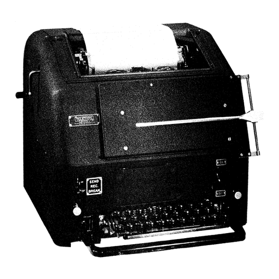
- Page 1 ''''' BULLETIN 138B ADJUSTMENTS TYPE BAR PAGE PRINTE R MODELS 15AND20 TELETYPE® CORPORATION 5555 TOUHY AVENUE, SKOKIE, ILLINOIS Copyright 1941, 1944 and 1955 by Teletype Corporation Printed in U. S. A.
- Page 5 138B TABLE OF CONTENTS Paragraph Paragraph Page Page Ribbon 03cillator Lever Spring SECTION 1 - ADJUSTMENTS Torsion Ribbon Shift Lever Spring Tension General Miscellaneous Instructions Margin Bell Pawl Spring Tension Manual Selection of Characters or Ribbon Lockout Bar Do=tent Spring Pressure Functions Ribbon Lockout Bar Detent Spring...
- Page 6 138B Paragraph Page Paragraph Page 73 . Selector Arm Pivot Screw 1-17 120. Pressure Roller Release Lever Selector Arm Bracket 1-17 Shafts 1-25 1-17 Locking Wedge 121. Paper Chute Spring Tension 1-25 Locking Lever Spring Tension 1-17 122. Paper Chute 1-25 .•...
- Page 7 138B Paragraph Page Paragraph Page Universal Function Lever Spring Line Relay Jack Contact Spring 201. 161. Tension 1-31 Tension 1-36b Upper Contact Lever Spring 162. Blank Function Lever Spring 202. 1-31 Tension Tension 1-36b Send-Receive Mechanism Plate 1-31 Lower Contact Lever Spring 163.
- Page 8 138B Paragraph Page Paragraph Page 234. Cover Paper Guide Posts 1-42 269. 1-48 Tabulator Bar 270. Contact Lever Screw 1-48 PLATEN INDEXING MECHANISM FOR 271. Tabulator Latch 1-48 SPROCKET FEED PRINTERS 272. Tabulator Latch Bar Extension 1-48 273. Tabulator Stops 1-48 235.
- Page 9 138B Page Page Paragraph Paragraph Contact and Backstop Bracket 1-58 Ribbon Oscillator Lever Latch 336. 303. 1-53 Bracket 337. Contact Lever Latch Mounting 1-58 Ribbon Oscillator Latch Spring Screw 304. 1-53 Upper Contact Spring Tension 1-58 Tension 338. 1-59 Ribbon Oscillator Lever Adjustable 339.
- Page 10 138B Paragraph Page Paragraph Page 368. Vertical Link Eccentric 1-62 392. Blank Contact Assembly 1-64a Switch Mounting Plate 369. 1-62 SECTION 2 - LUBRICATION END-OF-LAST-FORM INDICATING ME CHAN- ISM MOUNTED ON COVER OF SPROCKET General FEED PRINTERS Typing Unit Type Bar Carriage Assembly 370.
-
Page 11: Miscellaneous Instructions
The following requirements and adjusting Hold down the front edges of those vanes which procedures for the maintenance of the Teletype correspond to the marking impulses of the com Model 15 or Printer are arranged in a se... - Page 12 138B incoming signals, mounted at the left range. Note the position of the index arm on end of the main shaft. Before measuring the the scale. receiving range of a printer equipped with a pulling magnet selector, the armature spring Determine the opposite end of the receiving...
- Page 13 138 B REPLACING THE TYPE BAR C ARRIAGE ribbon carrier after disengaging it from the hook on the ribbon oscillator lever, and then Shift the platen to the FIGURES position lift the type bar guide off its dowels; raise and rotate the main shaft until the printing bail the type bar in question until it passes the is in its rear position.
-
Page 14: Plunger Guide Roller Bracket
138B eccentric mounting stud to obtain this require These requirements should be checked ment. with the range finder assembly removed. Pertains only to friction feed printers. 7. PULL BAR SPRING TENSION (Figure 3) See Notes (A) and (B) on Page 1-3 Pertains only to printers equipped with a send-receive mechanism. -
Page 15: Ribbon Feed Shaft Detent Spring
138B Position the code bar mounting plate by means increase or decrease the spring pressure, re of its elongated mounting holes to secure the move the spring and bend it. To equalize the specified clearance. pressure, position the spring to right or left. RIBBON FEED SHAFT BEARING PLATES 12.1 RIBBON RATCHET SHAFT GEARS BACK-... -
Page 16: Vertical Ribbon Feed Shaft Spur
138B spur gears should line up with their respective ribbon reverse arm, and if necessary, the set ribbon spool shaft spur gears. To adjust, posi screws of the collars and the link of the left tion the vertical ribbon feed shaft spur gears by ribbon reverse shaft. -
Page 18: Margin Bell Pawl Spring Tension
138B Preliminary: The end type ba:.. · s should rest 32. MARGIN BELL PAWL SPRING TENSION against the backstop along its entire width (Figure 14) - See Note (A) On Page 1-3 within .010" . Hook an 8 oz. scale, held in a horizontal Preliminary: With the type bars held in the position, over the margin bell pawl, just above guide against the platen, there should be at least... -
Page 19: Left Pull Bar Spring Bracket
138B NOTE loosen the lock nuts and position the cone nuts. The rollers s hould turn freely with a barely per If the second or third (Model 15) or sec ceptible amount of end play after the lock nuts are ond through seventh (Model 20) pull bar tightened. -
Page 20: Printing Bail
138B NOTE NOTE After checking the 22 to 30 ounce pull the clearance at one side is so un and with the clutch teeth still separated, equal to the clearance at the other side gradually reduce the tension exerted by that the .010"... -
Page 21: Function Lever Bail
138B the selected function lever and the front edge in its extreme rear position and the No. 1 (Model of the right projection of the function lever bail or No. (Model vane is held midway be 15 ) should be flush (within with the top front tween its MARKING and SPACING positions. -
Page 22: Sixth Vane
138B NOTE screw hole and pulled at right angles to the link, it should require some tension, not over 8 o:t:s., When checking the .008" to .030" clear to start the link moving. If necessary, remove ance, the forward edge of the sixth vane the link and adjust the slotted end to obtain this should be held in its lowermost position friction. -
Page 23: Selector Armature Bracket Link
138B No. 1 (Model 15) No. 0 (Model 20 ) sword SELECTOR ARMATURE BRACKET (Fig held against the upper separator plate without ure 33) - See Note (E) On Page 1-4 bending the latter. position armature bracket Armature end play taken up in a direction should be such as to provide some clearance, to reduce the specified clearance to a minimum. - Page 24 138B between the sword and the other stop post i5 detent or armature stop plate and operated at a more than .040", it will be necessary to refine speed less than 318 operations per minute. the 'SELECTOR ARMATURE BRACKET LINK" as follows: NOTE Loosen the armature bracket mounting...
- Page 25 138B that, when tightening the nut, the adjustment is the point of the locking lever when the locking lever is on the long high part of the locking cam not disturbed. and the two points are in line. To adjust, position the locking wedge forward or backward in its STOP LEVER SPRING TENSION (Figure slot in the armature extension by means of the...
- Page 26 138B until the stopping edge of the stop lever is 72. SELECTOR CORE ARMATURE directly below the latching surface of the trip ALIGNMENT (Figure 41) - See Note latch. While checking the above clearance, take On Page 1-4 up the play in the stop lever with a screwdriver applied axially adjacent to the spring hole as a.
-
Page 27: Selector Arm Pivot Screw
enough to make the bracket friction tight. Then, SELECTOR ARM PIVOT SCREW (Figure - See Note (E) On Page equalize the clearance between the swords stop posts, loosen centralizing eccentric screw lock nut and turn the eccentric With the armature lever spring, the selector arm spring, and selector arm stop detent spring screw clockwise to provide more clearance on unhooked, the selector arm should be free on its... -
Page 28: Selector Lever Spring
138B adjusting arm, using the 90783 adjusting wrench. NOTE To do this, insert the adjusting wrench in the When checking the MARKING position, hole above the end of the adjusting arm and be sure that the selector arm operating rotate the wrench. Tighten the bracket and ad screw does not interfere with the move... -
Page 29: Selector Arm Operating Screw
1 38B 82. ARMATURE LEVER SPRING TENSION 85. STOP LEVER ECCENTRIC SCREW (Figure 48) - See Note (E) On Page 1-4 (Figure 4 1) - See Note (E) On Page 1-4 a. Unhook the armature lever spring from The stop lever on the range finder assembly its spring arm and rotate the main shaft until should overtravel the latching face of the trip the armature lever is on a high part of its cam. -
Page 30: Trip-Off Screw
138B in its normal upright position. Disconnect the TRIP-OFF SCREW (Figure 49) line feed and shift-unshift vertical link at the There should be some clearance, not more upper shoulder screws. (See Figures 50 and 53) than . 004", between the stop lever and the trip Unhook the platen balance spring and the shift... -
Page 31: Function Lever Spring Tension
1 38 B Rotate the main shaft until the printing bail is lighter at the bottom of the character and lower it if the shading is lighter at the top. in its extreme rear position. Then unhook the (See Fig blank printing and spacing cutout function lever ure 50 for location of parts.) spring from the spring plate. -
Page 32: Platen Balance Spring Tension
138B tion is received, the UNSHIFT on space cutout SHIFT (Model 20) push bar when the platen is lever should be rotated countercloc'kwi se (as in the LETTERS (Model 15) SHIFT (Model 20) viewed from the bottom of the printer) against position. -
Page 33: Platen Shaft
138B Unhook the sixth vane detent spring from the eccentric screw nut (Figure 53) and turn the spring plate. When the platen is shifted to the eccentric screw so as to rotate the platen by SHIFT and UNSHIFT positions, the sixth vane means of the detent lever. -
Page 34: Line Feed Check Screw
138B to .030" clearance between the line feed check 111. LINE FEED DETENT LEVER SPR ING screw and each tooth on the detent ratchet, when TENSION the platen is rotated. To adjust, loosen the Model 15 (Figure 53) check post clamping nut and position the stop screw. -
Page 35: Paper Chute Spring Tension
138B 118. PRESSURE ROLLER RELEASE CAMS Model 20 Typing Unit (Figure 55) -See Note (F) On Page 1- 4 With the inner surface of paper chute On units equipped with six pressure roll mounting extensions against the casting, ers, following applies. With the pressure outer ends of the release lever shafts should roller release shaft arm in its rear position, the... -
Page 36: Paper Fingers Shaft Spring Tension
138B 124. PAPER FINGERS SHAFT SPRING TEN 129. SPACING ESCAPEMENT PAWL SPRING SION (Figure 56B) - See Note (F) On Page TENSION (Figure 57) 1- 4 Rotate the main shaft until the printing bail ts Hook a 32 oz. scale over the paper finger shaft in its extreme rear position. -
Page 37: Signal Bell Latch Bar Latch
138B NOTE vanes but is not selected. Hook a 4 lb. scale over the rear extension of the bell function lever On Model 15 typing units which ring the just in front of the lobe that engaged the bell bell on BLANK, set up the letter latch bar, and pull at right angles to the lever. -
Page 38: Carriage Return Lock Bar Latch Spring Tension
138B 142. CARRIAGE RETURN LOCK BAR LATCH the function bail in its extreme forward posi SPRING TENSION (Figure 60B) tion, and the carriage return latch bar tripped off its latch, hook an 8 oz. scale over the reset With the carriage return lock bar latch un bar just in front of the shoulder and pull hori... -
Page 39: Dashpot Lever Spring Tension
138B (4) Automatic Carriage Return and Line rear position, there should be some clearance, Feed Function Lever Eccentric Screw not more than .008", between the upper surface - Paragraph 294. of the guide screw heads and the upper surface (5) Mounting Bracket - Paragraph 295. of the groove in the front carriage track. -
Page 40: Sixth Vane Detent Spring Tension
138B strap, loosen the spacing rack mounting screws 159. PLATEN FRICTION ASSEMBLY (Figure and position the rack toward the front or rear. 64B) - See Note (F) On Page 1-4 Adjust for this backlash with the carriage in its extreme left and right hand positions and also Move the pressure roller release shaft arm in its center position. - Page 41 1 38B front end of the universal function lever exten NO TE sion and pull vertically upward. should re On Model 1 5 units equipped with a me quire 1 4 to 1 7 ozs. to start the lever moving. chanical motor stop mechanism, perform the following adjustments at this time.
- Page 42 138 B highest point of the main shaft gear. The NOTE lateral alignment of the motor pinion and the On Model 15 units equipped with a me main shaft gear should be such that the center chanical motor stop mechanism, perform line of the gear coincides with a vertical line the following adjustments at this time.
- Page 43 138B NOTE position (up) and loosen the ribbon oscillator lever clamping screw and nut. Position the ribbon On sprocket feed printers, perform the oscillator lever and tighten the clamping screw following adjustments at this time. and nut. Check this adjustment with the platen (1) Platen Roller Sprocket Rings - Para...
- Page 44 138B shaft. It should require ozs. to move 173.1 SELECTOR CAM SLEEVE ASSEMBL Y the cam in a direction opposite to its normal See Note (I ) on Page ( Applies to direction of rotation. W. P.M. Units) CAUTION Make certain that the felt washers of the se...
- Page 46 138B eccentric held against the clutch throwout lever, 185.1 UNIVERSAL BAR BEARING BRACKETS the end of the trip-off pawl should clear the end (Figure 150} - See Note On Page 1-4 of the intermediate pawl by not more than .004" a.
- Page 47 138B pressure at approximately the center of the bar, 197. LINE JACK SPRINGS there should be .010 " to .020 " clearance between the clutch throwout lever and the high part of the It should require 1 to 2 lbs. pressure, using throwout cam.
- Page 48 138B angles to the extension. It should require 1- 200. LINE RELAY J ACK CONTACT GAP (Fig ure 81B) - See Note (I) On Page 1-4 1/4 to 2-1/4 ozs. to start the pawl moviPg. When the jack plunger is held flush with 205.
- Page 49 138B tacts. Adjust t spring No. on the mounting Lrad:t:t, by bending c I<�;Ok u.c. '=>( Recheck (1). the spring mountin g hole leveL and pull in line w1th the sp,·ing. It should 1 e NOTE quire 1 to ozs. to start stop lever oving following...
- Page 50 if necessary, in cases where the clearance re (3) With the relay plunger in the unoperated quiremi=mts given in the following paragraphs position, hook an oz. scale over the middle cannot be met. contact spring, as close as possible to the wiper contact, and pull at a right angle to the spring.
- Page 51 lever with the projecting lug on the operating 216. SPEED ADJUSTING WHEEL F RICTION end pointing downward. Insert the shoulder WASHER SPRING TENSION (Figure 88) screw and replace the lock nut. See Note (H) on Page 1-4. a. Turn the adjusting wheel so that the ten 214.
- Page 52 138B that part of governor cover on which when the wheel is opposite the wearing strip, the target is mounted. (Figure 90B) the wearing strip is tight against the casting, and all the end thrust of the motor armature The bracket should be parallel to the is taken up in a direction to make this clear...
- Page 53 138B j. Apply the push end of a 12 lb. scale against 227. LEFT PRESSURE ROLLER SPRING the fan end of the shaft and push parallel to the TENSION (Figure 92) shaft. It should require at least lbs. pressure to start the shaft moving. Hook an 8 oz.
- Page 54 138B dashpot lever applied just in front of the should NOTE ers), there is a slight clearance, not more than .002", between the end of the screw and the On units equipped with a handwheel in dashpot lever. Turn the left margin adjusting place of the platen crank, position the screw one-sixth turn in a direction to eliminate handwheel so that the 1/8"...
- Page 55 138B guide should have a similar clearance. Adjust the cam, to rotate the cam counterclockwise. by positioning the guide posts in their elongated To adjust, remove the two stop screws from mounting holes. the hand wheel. Rotate the hand wheel counter clockwise until the cam surfaces are at the top.
- Page 56 138B position, hook an 8 oz. scale over the head of BACKSTOP STOP LEVER MOTOR the screw which mounts the motor stop lever SCREW (Figure 97) eccentric and pull toward the rear of the printer. It should require 1 to 1-1/2 ozs. to start the With the platen in the LETTERS position, set lever moving.
- Page 57 138B main shaft until the function bail roller just stop pawl engaged with its latch, there should leaves the cam surface of the blank function be a gap of .012" to .020" between the contacts. lever. Then depress the break key and im...
- Page 58 138B To adjust, position the trigger guide by 256. MOTOR STOP FUNCTION LEVER ' means of its elongated mounting holes. SPRING TENSION Position the 889 69 spring above the block With the motor stop function l�ver against the rear edges of the vanes, but not selected, ing lever.
-
Page 59: Armature Stops
138B its pole faces, hook an 8 oz. scale over the end than .004" clearance between the stop magnet the spring post on the start magnet armature armature and either the stop magnet core or and pull horizontally in line with the spring. It yoke, if it fails to touch either one. - Page 60 138B d. The long contact spring farthest from the a. With the tabulator latch bar (Figure 109) stop magnet armature should bear lightly against in its upper position and the send-receive lever the long contact spring nearest the stop magnet (if present) in the SEND position, there should be some clearance, not more than .008", be...
- Page 61 138B b. With the carriage in position for the first 276. TABULATOR LATCH SPRING character of a tabulated column and the spacing (Figure 109A) escapement ratchet stopped by the rear spacing With the typing unit resting on its right side escapement pawl, position a tabulator stop to the and the printing bail in its extreme rear position, left of the carriage pawl, allowing .008"...
-
Page 62: Magnet Bracket
138B 282. spring, there should be a clearance of SIGNAL BELL H AMMER BACKSTOP .040" .080" 1 -3. between the lower edge of the See Note (A) on Page stop lever and the right side of a tooth on the spacing stop sleeve when the tooth is opposite Apply standard adjusting procedure as pre... - Page 63 138B near the spring hole and pull at a right angle to horizontal portion of the pawl and push a ... ward. It should require 1-1/2 to 3 ozs. to sta1. the lever. It should require 1 to 2 ozs. to start the lever moving.
- Page 64 138B motor stop function lever blocking lever carriage return function lever. When may be ignored. checking this clearance, the shoulder on the carriage return latch bar should be fully latched With the trigger guide positioned in ap· on the latch. To adjust, position the carriage proximately the middle of its adjustable range, return function lever eccentric mounting screw.
- Page 65 138B ribbon oscillator is not resting against the rib CARRIAGE RETURN bon oscillator lever adjustable stop. If neces With the carriage return combination fully sary, loosen the screws and move the adjustable selected and with the carriage return function stop out of the way. (Adjustable stop is shown lever resting against the vanes, unhook the in Figure 121.) Manually place the ribbon oscil...
- Page 66 138B With the magnet de-energized and with the Select any character that prints and rotate the armature backstop eccentric positioned to give main shaft until the printing bail is in its ex maximum travel of the armature, the front edge treme forward position.
- Page 67 138B c. With the contact operating lever in its 316. TYPE BAR GUIDE latched position (Figure 126B) there should be some clearance, not more than .010" between Bend the type bar guide forward approximately the short contact spring and the contact spring .025"...
- Page 68 138B 10 adjust, loosen the counter mounting and pull in line with the link. It should require screws. Then turn the typing unit main shaft from 54 to 64 ozs. to stretch the spring to po unitl the printing bail is rotated to the extreme sition length.
- Page 69 138B wheel is pointing downward. To adjust, bend the Under this condition, the turnbuckle should be adjusted so that the platen has rotated two upper contact spring. line-spaces, that the detent roller rests in the 324. CONTACT BRACKET ASSEMBLY hollow between two ratchet teeth and that the ADJUSTMENT feed pawl is still in engagement with a ratchet tooth to such an extent that there is no clearance...
- Page 70 138 B than .015", between the blocking arm of the 335. PRINTING CUTOUT LATCH SPRING shift function lever and the blocking surface of TENSION (Figure 129) blocking plate. To make this adjustment, first position the eccentric so that the high With the printing bail in its extreme forward part is toward the rear of the typing unit, then position, hook an 8 ounce scale v.nder the print...
- Page 71 138B start insulator moving away from ADJUSTMENTS PRINTERS EQUIPPED contact lever. To adjust, bend the upper contact FOR STATION SELECTOR OPERATION spring. TYPING UNIT ADJUSTMENTS 339. LOWER CONTACT SPRING TENSION 344. CALL-CONTACTS (Figure 133) (Figure 131) Hook an 8 oz. scale over the lower contact a.
- Page 72 should be a clearance of .010" .020" between the transfer contact lever and the insulator on the disconnect contacts. adjust, bend the the center contact spring. To adjust, loosen the stiffener to obtain this clearance. screws which secure the transfer contact brack to the send-receive plate, and position the With the main shaft in its STOP position.
- Page 73 355. 139) BAIL (Figure KEYBOARD CAM OPERATED CONTACTS ADJUSTMENTS The eccentric bushing on the bail which is engaged in the forked end of the answer-back 359. PULSING CONTACT magnet armature lever should be adjusted to Rotate the keyboard shaft untif1the clutch provide full travel...
- Page 74 138 B With the printing bail in its extreme rear eye, it should require 40 to 50 ozs. to pull position the insulator on the center contact the spring to position length. spring should juEt touch the end of the contact lever.
- Page 75 138B rollers are raised as for the insertion of new there should also be some clearance between forms. To adjust, loosen the mounting screws the strippers and the platen roll sprocket rings. Adjust by means of the stripper locating collars . and position the switch mounting plate .
- Page 76 138B 383. RIBBON OSCILLATOR A D J U S T A B L E PAPER-OUT MECHANISM STOP (Figure 121) 379. SWITCH PLUNGER OVERTRAVEL a. Remove the type bar carriage from the unit and position the oscillator lever adjustable Adjust the operating screw, which cams the stop so that there is some overtravel of the switch operating bracket, so that it just activates oscillator extension over the stop plate (exten...
- Page 77 138B UPPER CASE "H" OR "BLANK" CON SIGNAL BELL LATCH BAR LATCH- Same 389. TACTS as paragraph 134. TYPING UNIT SLIP CONNECTION SPRING 386. - Same as paragraph 199. CARRIAGE RETURN LATCH BAR LATCH 390. - Same as paragraph 140. UPPER CASE "H"...
- Page 78 The following lubricants have been stand (6) Operate the handle back and forth for ardized for use on all types of Teletype appa several strokes or until lubricant is pumped from ratus. These lubricants supersede those re...
- Page 79 138B (15) Ribbon feed mechanism gears. the plunger of the gun. Care should be taken that the bearings are not overloaded. Overloading will result in the grease oozing out of the end (16) Ribbon spool shafts bushings - remove castings and being forced into the motor or being spools.
- Page 80 (11) Paper straightener rod supporting lev (10) Spacing clutch spring coils (per er bearings. mitting oil to flow between prongs of driven member of spacing clutch and worm gear sleeve.) (12) Pressure roller release shaft and crank (11) bearings. Spring (coils) which compresses fric tion washers of selector cam assembly - (oil (13) will flow between prongs of nut on main shaft...
- Page 81 138B (5) Roller surface to have film of grease. (3) Carriage return push bar and latch bar operating lever shoulder screw. (6) Function bail and printing bail oper ating arm and rollers (oil-grease-oil). (4) Carriage return locking bar bell crank link shoulder screw.
- Page 82 138B (1) Key levers - in front comb. (3) Bell crank lever and operating lever joint. (2) Space bar loop - on space bar loop (4) Shift vertical link, lower end and detent shaft. lever shoulder screw. (3) Keyboard shaft - two oil cups. j.
Need help?
Do you have a question about the 15AND20 and is the answer not in the manual?
Questions and answers