Table of Contents
Advertisement
Quick Links
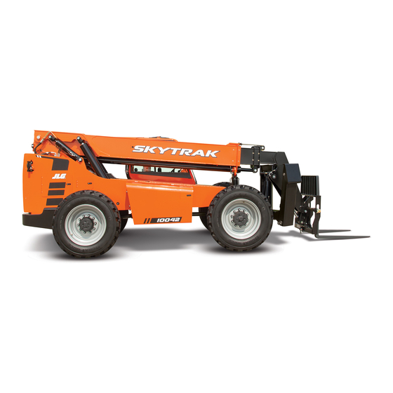
Service Manual
Models
6036, 6042, 8042,
10042 & 10054
SN 0160069719 to Present
including 0160065791, 0160065792, 0160065796,
0160065798, 0160065824, 0160065825,
0160065826, 0160069336, 0160069359,
0160069383, 0160069411, 0160069441,
0160069566, 0160069567 & 0160069568
31211015
Revised
July 31, 2017
An Oshkosh Corporation Company
Advertisement
Table of Contents
Troubleshooting


Need help?
Do you have a question about the 6036 and is the answer not in the manual?
Questions and answers