
Related Manuals for Thermo King MAGNUM


Summary of Contents for Thermo King MAGNUM
- Page 1 Maintenance Manual SB-210+ SB-210+ MAGNUM Additional text information Additional text information to be placed here to be placed here TK 51122-4-MM (Rev. 6, 02/06) TK 5XXXX-X-PL TK 5XXXX-X-PL...
- Page 2 MAGNUM TK 51122-4-MM (Rev. 6, 02/06) Copyright© 2004 Thermo King Corp., Minneapolis, MN, USA. Printed in USA.
- Page 3 Thermo King Corporation should be consulted if further information is required. Sale of product shown in this manual is subject to Thermo King’s terms and conditions. This includes, but not limited to, the Thermo King Limited Express Warranty. Such terms and conditions are available upon request.
- Page 4 Ester compressor oil in tightly sealed containers. If Polyol Ester oil becomes contaminated with moisture or standard oils, dispose of properly–DO NOT USE. When servicing Thermo King R-404A unit, use only those service tools certified for and dedicated to R-404A refrigerant and Polyol Ester compressor oils.
- Page 6 Table of Contents List Of Figures ................11 Safety Instructions .
- Page 7 Table of Contents Navigating the Controller Operating Menu ........... 45 Navigating the Controller Operating Menu .
- Page 8 Table of Contents Operating Instructions (continued) Starting the AFAM System ..............87 Change the AFAM Delay .
- Page 9 Reversing Power Phase on MAGNUM Units ........
- Page 10 Table of Contents Refrigeration Maintenance (continued) Economizer Expansion Valve Replacement ........... 146 Economizer Heat Exchanger Replacement .
- Page 11 Table of Contents...
-
Page 12: List Of Figures
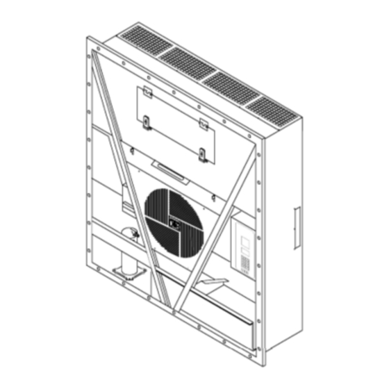
Figure 3: MAGNUM Unit ........ - Page 13 Figure 71: MAGNUM 20 Evaporator Coil (Defrost) Sensor Location ....... .
-
Page 14: Safety Instructions
Safety Instructions General Precautions Refrigerant Oil Precautions • Always wear goggles or safety glasses. Observe the following precautions when working Refrigerant liquid and battery acid can with or around refrigerant oil: permanently damage the eyes. • Do not allow refrigerant oil to contact your •... -
Page 15: First Aid
Safety Instructions • Be certain the unit power plug is clean and dry Check immediately for the presence of a pulse and before connecting it to a power source. respiration after separating the victim from power source. If a pulse is not present, start CPR (Cardio •... -
Page 16: Welding Of Units Or Containers
Safety Instructions are available at most electronic equipment • Weld unit and/or container per normal distributors. Do not wear these straps with welding procedures. Keep ground return power applied to the unit. electrode as close to the area to be welded as practical. -
Page 17: Identifying Unit Safety And Warning Decals
Locating Serial Numbers Warning Decals Serial numbers can be found on the component’s nameplate. Serial number decals, refrigerant type decals and warning decals appear on all Thermo King ® • Electric Motor Nameplate: Attached to the equipment. These decals provide information that motor housing. -
Page 18: Service Guide
Service Guide Service Guide A closely followed maintenance program will help to keep your Thermo King unit in top operating condition. The following service guide table should be used as a guide when inspecting or servicing components on this unit. - Page 19 Service Guide...
-
Page 20: Specifications
Specifications System Net Cooling Capacity— Full Cool MAGNUM, MAGNUM SL Models — Air Cooled Condensing* 460/230V, 3 Phase, 60 Hz Power 380/190V, 3 Phase, 50 Hz Power Net Cooling Capacity Power Net Cooling Capacity Power Return air to Consump Consump... -
Page 21: Evaporator Airflow Specifications
Specifications MAGNUM 20 Model — Air Cooled Condensing* 460/230V, 3 Phase, 60 Hz Power 380/190V, 3 Phase, 50 Hz Power Net Cooling Capacity Power Net Cooling Capacity Power Return air to Consump Consump evaporator coil 60 Hz 60 Hz 60 Hz Power... -
Page 22: Electrical System Specifications
Specifications MAGNUM 20 460/230V, 3 Phase, 60 Hz Power 380/190V, 3 Phase, 50 Hz Power External Static Pressure (water High Speed Low Speed High Speed Low Speed column) /min /min /min /min 0 mm (0 in.) 4,000 2,350 2,000 1,180... -
Page 23: Refrigeration System Specifications
32 ± 4.5 C (90 ± 8 F) Refrigeration System Specifications Compressor: Model No.: ZMD18KVE-TFD-277, Scroll Refrigerant Charge: MAGNUM, MAGNUM SL, MAGNUM 20 4.0 Kg (8.0 lb.) R-404A Water-Cooled Condenser-Receiver Tank (Option) 4.8 Kg (8.8 lb.) R-404A Compressor Oil Capacity 1.77 liter (60 oz.)*... -
Page 24: Normal R-404A System Operating Pressures (Scroll Compressor)
Specifications Refrigeration System Specifications (Continued) Vapor Injection Control: Vapor injection valve is energized (open) continuously when the compressor duty cycle (ON time) is 100 percent (Full Cool). High compressor discharge temperature may cause Modulation Cool or Power Limit the vapor injection valve to energize (open) but only while the Compressor Digital Control valve is not energized (closed). -
Page 25: Mp-3000A Controller Specifications
Specifications MP-3000a Controller Specifications Temperature Controller: MP-3000a microprocessor with thermostat, digital thermometer, Type programming keypad, mode indicators, LED display and LCD display for displaying unit operating and cargo information Setpoint Range -35.0 to +30.0 C (-31.0 to +86.0 F) Digital Temperature Display -60.0 to +80.0 C (-76.0 to +176.0 F) Controller Software (Original Equipment): Version... - Page 26 Specifications MP-3000a Controller Specifications (Continued) Compressor Shutdown Protection (Auto Reset): Stops Compressor 148 C (298 F) Allows Compressor Start 90 C (194 F) Bulb Mode: Flow High: High speed only Flow Low: Low speed only Evaporator Fan Speed Settings Flow Cycle: Fans will cycle between low and high speed every 60 minutes Defrost Termination Temperature Setting 4 to 30 C (40 to 86 F)
-
Page 27: Physical Specifications
335.0 mm (13.18 in.) from back of flange MAGNUM SL 378.0 mm (14.88 in.) from back of flange MAGNUM 420.0 mm (16.54 in.) from back of flange J = MANGUM and MAGNUM SL Evaporator Access Door K = MAGNUM 20 and MAGNUM SL Evaporator Access Door... - Page 28 Specifications AMA313 Figure 2: Physical Specifications...
-
Page 29: Metric Hardware Torque Charts
Specifications Metric Hardware Torque Charts Bolt Size Bolt Type and Class* N.m (Ft.-lb.) N.m (Ft.-lb.) N.m (Ft.-lb.) N.m (Ft.-lb.) HH – CL 5.8 6-9 (4-7) 12-16 (9-12) 27-34 (20-25) 48-61 (35-40) HH – CL 8.8 10-13 (7-10) 20-27 (15-20) 41-47 (30-35) 75-88 (55-65) HH –... -
Page 30: Unit Description, Features & Options
The unit is designed to cool and heat containers for shipboard or overland transit. The unit mounts in the front wall of the container. MAGNUM SL and MAGNUM 20 units feature a slimline frame. AMA306... -
Page 31: Scroll Compressor
Unit Description, Features & Options Scroll Compressor MP-3000a Controller The scroll compressor features a digital port and The MP-3000a is an advanced microprocessor an intermediate suction port. controller that has been specially developed for the control and monitoring of refrigeration units. Digital Port See “Controller Description and Operating Chapter”... -
Page 32: Economizer Heat Exchange System
Unit Description, Features & Options Economizer Heat Exchange Fresh Air Exchange System System The fresh air exchange system removes harmful gases from containers carrying sensitive An economizer heat exchange system replaces the perishable commodities. The fresh air vent is conventional heat exchanger. The economizer located above the control box. -
Page 33: Receiver Tank Sight Glass
Evaporator Fans operates continuously in high ambients. In low ambient conditions, the controller cycles the MAGNUM models are equipped with either 2 or condenser fan on and off to maintain a minimum 3 evaporator fans. All models feature 2-speed condenser temperature. The controller maintains a motors. -
Page 34: Unit Options
Unit Description, Features & Options Unit Options Recording Thermometer (Optional) The recording thermometer indicates and This unit is available with several options that are permanently records the temperature of the air listed in Figure 11. These options are specified returning to the evaporator section on a calibrated when placing the order. -
Page 35: Usda Cold Treatment Temperature Recording (Optional)
Unit Description, Features & Options USDA Cold Treatment Temperature Condenser Fan Switch (Optional) Recording (Optional) The Condenser Fan switch is provided on the The MP-3000a controller includes provisions for control box with the water-cooled condenser the use of three or four USDA sensors. These option. -
Page 36: Plus (Afam+) (Optional)
Unit Description, Features & Options Advanced Fresh Air Management (AFAM) and Advanced Fresh Air Management Plus (AFAM+) (Optional) An advanced microprocessor controlled fresh air management system provides: • programmable control of the air exchange rate • programmable delayed vent opening •... - Page 37 Unit Description, Features & Options Evaporator Access Door Condenser Fan Compressor Compartment Scroll Compressor Control Box Rear Download and USDA Receptacle Panel (Access from Inside Container) Figure 14: Unit Front View...
- Page 38 Unit Description, Features & Options AXA0238 Evaporator Grille Air Channels Fresh Air Inlet Top Rear Plate Bottom Rear Plate USDA Receptacle Panel: • Controller Communications and Data Download Port • USDA1/Spare 1 Sensor Connection • USDA2/Spare 2 Sensor Connection • USDA3/Spare 3 Sensor Connection •...
- Page 39 Unit Description, Features & Options AJA1986 Expansion Valve Ball Valve Evaporator Coil Digital Control Valve Expansion Valve (Economizer) Low Pressure Cutout Switch Condenser Coil 10. Economizer Heat Exchanger Water Cooled Condenser Tank Vapor Injection Solenoid Valve Scroll Compressor 12. Dehydrator Figure 16: Refrigeration System...
- Page 40 Unit Description, Features & Options Sensor Kit 15. Heater Bracket Evaporator Fans Harness 16. Solenoid Valve Power Cable Bracket 17. Thermostat, Defrost Termination Power Cable 18. Scroll Compressor Power Plug 19. Control Box LPCO Switch 20. Compressor Cable Heater Spring 21.
- Page 41 Unit Description, Features & Options...
-
Page 42: Controller Description
Controller Description Controller Description The MP-3000a is an advanced microprocessor controller. It has been specially developed for the control and monitoring of refrigeration units. The controller contains the following basic features: Displays the Temperature Status Display: controlling sensor temperature (return or supply). Also has 8 status indicator LED’s. -
Page 43: Temperature Status Display
Controller Description Temperature Status Display Message Display The Temperature Status Display consists of two The Message Display shows setpoint temperature areas: A 5 digit LED display that shows the sensor during normal operation. temperature in Fahrenheit or Celsius and 8 status Alarms, messages and the controller menu also indicator LED’s. -
Page 44: Keypad
Controller Description Keypad • Data logger Menu • Miscellaneous Functions Menu The keys are used to scroll through the Controller menu and enter text and numeric characters. • Configuration Menu • Commands Menu Menu Scrolling Keys NOTE: The screens that display on the Display menus: The MP-3000a controller controller are determined by the controller contains an extensive display menu that can be... - Page 45 Controller Description Text Input Example The following paragraph gives an example of how to enter text to an informational screen. To enter “THERMO” in an information screen: • Enter “T” by pressing the F3 key, then pressing STU key. • Enter “H”...
-
Page 46: Navigating The Controller Operating Menu
Navigating the Controller Operating Menu Navigating the Controller Operating Menu The MP-3000a contains an extensive operating menu. The menu is navigated via the controller keypad. The Main menu is divided into eight major areas: • Setpoint • Alarm List • Data •... - Page 47 Navigating the Controller Operating Menu 1. Display menus: The MP-3000a controller • Data logger Menu: Menu screens in this contains an extensive display menu that can be group display temperature log, event log, navigated via keypad. The display menu is set log time and PTI log.
-
Page 48: Operating Instructions
Operating Instructions Unit On/Off Switch • Evaporator fans operate on high speed at setpoints of -9.9 C (14.1 F) and above. The unit control box has a two position toggle • Evaporator fans operate on low speed at switch to turn power On or Off to the unit. setpoint temperatures of -10 C (14 F) and •... -
Page 49: Change The Setpoint
Operating Instructions Initiating a Manual • Voltage measuring circuits Defrost Output signals from the controller automatically regulate all unit functions including: Turn the U switch O . Complete the • Compressor operation following steps: • Condenser fan operation 1. Press the D key. -
Page 50: Display Alternate Fahrenheit (F) Or Celsius (C) Temperatures
Operating Instructions 3. The display then returns to controlling sensor temperature when S key is released. Display Alternate Fahrenheit (F) or Celsius (C) Temperatures The controller can display temperatures in Celsius or Fahrenheit. Turn the U switch O and complete the following steps to display in fahrenheit or celsius: 1. -
Page 51: Setpoint Menu
Operating Instructions Setpoint Menu NOTE: All screens are NOT present on all units. The Pressing the S key displays the following ETPOINT screens that display on the controller are determined by list of tasks and values that can be activated or set: Controller Software settings and the options... -
Page 52: Change The Setpoint Temperature
Operating Instructions Change the Setpoint Temperature • [FLOW HIGH]: Evaporator fans operate continuously on high speed. See “Changing the Setpoint”. • [FLOW LOW]: Evaporator fans operate Change Condenser Fan Mode continuously on low speed. 1. Press the S 5. Press and hold the F4 key until the cursor key. -
Page 53: Change The Economy Mode Setting
Operating Instructions NOTE: The humidity setpoint should be NOTE: All screens are NOT established by the shipper. Always check that present on all units. The screens that display on the the setpoint entered in the LCD display is controller are determined by correct before proceeding. -
Page 54: Change The Humidity Setpoint
Operating Instructions Change the Humidity Setpoint NOTE: All screens are NOT present on all units. The 1. Press the S key. The Setpoint menu ETPOINT screens that display on the controller are determined by appears with the cursor in the [TEMP SETP] Controller Software settings and the options... -
Page 55: Alarms Menu
Operating Instructions Alarms Menu The Alarm List menu displays alarm codes. NOTE: All screens are NOT present on all units. The Alarm codes are recorded in the controller screens that display on the controller are determined by memory to simplify unit diagnosis procedures. Controller Software Some alarm codes are only recorded during a... - Page 56 Operating Instructions 3. Repeat above step until all alarm codes have been recorded. Press the F3 key to scroll backward to return to a previous alarm code. 4. To clear all alarm codes from the current display list and turn off the Alarm LED, all problems must be corrected and the alarm code “acknowledged”...
-
Page 57: Alarm List
Operating Instructions Alarm List (Continued) Alarm List Alarm Alarm Type Description Type Description Code Code Check Check Probe Error Check Supply Air Sensor Open Circuit Check High Pressure Cutout Check Supply Air Sensor Short Check Check Switch Off Error Circuit Check High Pressure Cutout Check Return Air Sensor Open Check... -
Page 58: Data Menu
Operating Instructions Data Menu • Current Phase 1 (Main Power Supply) • Current Phase 2 (Main Power Supply) The Data menu displays general unit operating • Current Phase 3 (Main Power Supply) information including sensor temperatures, unit electrical data, etc. A complete listing of the •... -
Page 59: Rmm State Menu
Operating Instructions RMM State Menu NOTE: All screens are NOT present on all units. The The RMM (Remote Monitoring Modem) State screens that display on the controller are determined by menu displays the current communications status Controller Software settings and the options with a REFCON system: installed on the unit. -
Page 60: Datalogger Menu
Operating Instructions Datalogger Menu NOTE: All screens are NOT present on all units. The The Datalogger menu contains a list of functions screens that display on the controller are determined by that display unit operating information recorded in Controller Software settings and the options the MP-3000a datalogger. -
Page 61: Inspect Event Log
Operating Instructions 3. Press the F4 key to access the Datalogger W = Warning in Last Interval menu. [INSPECT TEMP LOG] appears in the C = CO Active LCD display. NOTE: All event flags that occurred during a 4. Press the F4 key to enter Temp Log. LCD log interval are displayed. - Page 62 USDA temperature recording requirements. installed on the unit. Calibrate the sensors in an ice bath. MAGNUM units equipped for NTC style USDA sensors require USDA sensor P/N (refer to Tool Catalog). MAGNUM units equipped for PT100 style USDA...
-
Page 63: Set Trip Start
Operating Instructions Set Trip Start The controller displays the actual temperature offset when the sensor temperature is within 0.3 C With the U switch O and the LCD (0.5 F) above or below 0 C (32 F). display showing the standard display (setpoint): NOTE: The sensors should be in the ice bath 1. -
Page 64: Set Log Time
Operating Instructions Set Log Time NOTE: All screens are NOT present on all units. The With the U switch O and the LCD screens that display on the display showing the standard display (setpoint): controller are determined by Controller Software settings and the options 1. -
Page 65: Inspect Event Log
Operating Instructions Inspect Event Log Event Examples With the U switch O and the LCD • Controller alarm status (alarms set/cleared) display showing the standard display (setpoint): • Main power On/Off status (humidity On/Off, 1. Press the F2 or F3 key to enter Main menu. temperature setpoint, and main power Hz) 2. -
Page 66: Configuration Menu
Operating Instructions Configuration Menu NOTE: All screens are NOT present on all units. The The Configuration menu displays a list of screens that display on the controller are determined by functions that identifies unit operating features Controller Software settings and the options and current settings. - Page 67 NONE, LOW, HIGH, HIGH+LOW. number. Displays zero current On or Off. Zero Current: NOTE: MAGNUM units without a container number beginning with MAE, MSF or MWC View display on or off value (factory Supply LH: must be set for USDA temperature sensing. See default = off).
-
Page 68: Misc. Functions Menu
Operating Instructions Misc. Functions Menu NOTE: All screens are NOT present on all units. The The Misc. Functions menu displays a list of screens that display on the controller are determined by functions that identifies trips and determines how Controller Software settings and the options the controller records and displays operating... -
Page 69: Set Date And Time
Operating Instructions Set Date and Time View or Set Run Time 1. Press the F2 or F3 key to enter the menu list. 1. Press the F2 or F3 key to enter the menu list. Press the F2 or F3 key to scroll to [MISC. Press the F2 or F3 key to scroll to “MISC. -
Page 70: Set Cargo Data
Operating Instructions Set Cargo Data When the F1, F2, F3 or F4 key is pressed • to enter a character in the display, the 1. Press the F2 or F3 key to enter the menu list. keypad remains on that “character level” Press the F2 or F3 key to scroll to [MISC. -
Page 71: Commands Menu
Operating Instructions Operating Instructions Commands Menu NOTE: All screens are NOT present on all units. The The Commands menu displays a list of tasks that screens that display on the controller are determined by can be activated. The following commands are Controller Software settings and the options... -
Page 72: Brief Pti (Pretrip) Test
PTI test ends automatically. Press any key on the controller to return the unit to normal operation. See the following [MAGNUM Brief Pretrip (PTI) Test Procedure] for a detailed description of the PTI Test. Detailed PTI test results are stored in the MP-3000a Datalogger for later viewing. - Page 73 2.4A 2.3A 2.4A 2.1 Amps approx. at 50 Hz, 2.5 Amps approx. at 60 Hz • MAGNUM SL and MAGNUM 20: 2.7 Amps approx. at 50 Hz, 3.2 Amps approx. at 60 Hz Amperes are recorded in PTI log. PROBE TEST...
- Page 74 Operating Instructions MAGNUM Brief PTI Test LCD Display* Description Possible Duration Alarms (Time) COND FAN TEST Condenser fan is turned on. 16, 17 10 seconds SUP RET EVA Amp draw is measured and compared to voltage and frequency: 1.5 Amps at 60 Hz, 1.2 Amps at 50 Hz.
- Page 75 Operating Instructions MAGNUM Brief PTI Test LCD Display* Description Possible Duration Alarms (Time) PTI PART 1 END None 5 seconds SUP RET EVA “PTI Part 1 end” is recorded in PTI log. 5.1C 5.0C 5.1C 2.3A 2.1A 2.3A Unit will remain OFF until any key is pressed.
-
Page 76: Pti (Full Pretrip) Test
Figure 41: Full PTI Test 1. Press the F2 or F3 key to enter the menu list. See the following pages for the “MAGNUM PTI 2. Repeatedly press the F2 or F3 key to scroll (Full Pretrip) Test Procedure” for a detailed through Main menu until [COMMANDS] description of the PTI Test. - Page 77 Operating Instructions MAGNUM PTI Full Pretrip Test LCD Display* Description Possible Duration Alarms (Time) PTI START Event Log for PTI begins. None 2 seconds All alarms are turned off. Alarm list is cleared. Activated All relays are turned off and air vent are closed.
- Page 78 Operating Instructions MAGNUM PTI Full Pretrip Test LCD Display* Description Possible Duration Alarms (Time) COND FAN TEST Condenser fan is turned on. 16, 17 10 seconds SUP RET EVA Amp draw is measured and compared to voltage and frequency: 1.5 Amps at 60 Hz, 1.2 Amps at 50 Hz.
- Page 79 Operating Instructions MAGNUM PTI Full Pretrip Test LCD Display* Description Possible Duration Alarms (Time) PRE COOL/HEAT TEST If the return air temperature is above +20C (68F), unit None 30 to 60 operates in cool until the return sensor is less then +15C...
-
Page 80: Function Test
Figure 42: Function Test automatically. Unit automatically returns to normal operation. See “MAGNUM Function Test Procedure” in the following table for a detailed description of the Function Test. Any alarm codes recorded during the test can be viewed through the controller’s... - Page 81 2.4A 2.3A 2.4A 2.1 Amps approx. at 50 Hz, 2.5 Amps approx. at 60 Hz • MAGNUM SL and MAGNUM 20: 2.7 Amps approx. at 50 Hz, 3.2 Amps approx. at 60 Hz Amperes are recorded in PTI log. AFAM+ TEST...
- Page 82 Operating Instructions MAGNUM Function Test LCD Display* Description Possible Duration Alarms (Time) HEAT ELEMENT TEST Electric heaters are turned on. 10, 11 10 seconds SUP RET EVA Amp draw is measured and compared to voltage: 1.3C 1.0C 1.3C • 4.4 Amps approx. at 400V;...
-
Page 83: Manual Function Test
Operating Instructions Manual Function Test NOTE: All screens are NOT present on all units. The The Manual Function Test menu allows screens that display on the controller are determined by technicians to perform specific diagnostic tests on Controller Software individual components or turn several settings and the options installed on the unit. -
Page 84: Power Management
Operating Instructions 2. Press the F4 key to turn the component on. 2. Press the F4 key to access the Commands menu. The first command in the submenu 3. Press the F3 key to scroll to select next (Defrost) appears in the LCD display. component. -
Page 85: Manual Emergency Mode Operation
Monitor container temperature with an 6. Start the unit by turning the unit 460/380V external thermometer. main circuit breaker on. NOTE: On MAGNUM units, both the To select Manual Control: 460/380V main circuit breaker and the Unit 1. Turn the U... -
Page 86: Advanced Fresh Air Management (Afam) System (Optional)
Operating Instructions Advanced Fresh Air AFAM Operation Management (AFAM) System The system is pre-calibrated for air exchange rates (Optional) of 0 to 280 m /hr. (0 to 165 ft /min.). The actual door position is based on the air exchange setting An advanced microprocessor controlled fresh air and the power supply frequency. -
Page 87: Vent Door Assembly
Operating Instructions Vent Door Assembly A microprocessor controlled vent door provides programmable control of the air exchange rate. The vent door is adjusted to the desired position by a vent door motor and linkage assembly, shown in Figure 46. The system is pre-calibrated for air exchange rates of 0 to 280 m /hr. -
Page 88: Starting The Afam System
Operating Instructions Starting the AFAM System 1. Press the S key. The Setpoint menu ETPOINT appears with the cursor in the [TEMP SETP] line. 2. Press the F2 or F3 key to scroll to [AFAM] Setpoint Menu line. - Opti-Set - Temp. -
Page 89: Change The Afam Rate
Operating Instructions 5. Press and hold the F4 key until the cursor stops flashing. The new time delay is recorded in the controller and appears in the LCD display. 6. Press the ESC key to exit the Setpoint screen. Change the AFAM Rate NOTE: The fresh air exchange rate should be established by the shipper. -
Page 90: Advanced Fresh Air Management Plus (Afam+) System
Operating Instructions Advanced Fresh Air Management Plus (AFAM+) System An advanced microprocessor controlled fresh air management system that provides: • programmable control of the CO level in the container • data logging of the CO gas level reading • gas sensor unit •... - Page 91 Operating Instructions WARNING: The vent door and motor actuator arm move immediately again when the a delay is entered. Keep hands and tools away from the air exchange system components to prevent personal injury or unit damage. 5. Press and hold the F4 key until the cursor stops flashing.
-
Page 92: Opti-Set
Operating Instructions OPTI-SET Automated Fresh Air Exchange Management is designed for simple operation with the flexibility to handle a variety of commodities and situations. OPTI-SET allows all of the following variables to Setpoint Menu be set by selecting a specific commodity. If - Opti-Set OPTI-SET is turned ON, a list of all available - Temp. -
Page 93: Changing The Afam+ Settings Using 'Optiset' (Sets 'Demand' Mode)
Operating Instructions 5. With the mode setting in the menu line, press • Defrost Termination Temperature and hold the F4 key until the cursor stops • Economy Mode flashing. The new mode setting will appear on the LCD display. • Humidity Control 6. -
Page 94: Changing The Afam Mode To 'Units
Operating Instructions 9. Press and hold the F4 key until the cursor 14. Press and hold the F4 key until the cursor stops flashing. The new rate is recorded in the stops flashing. Door will calibrate to open datalogger and appears on the LCD display. position and the new rate is recorded in the datalogger and appears on the LCD display. -
Page 95: Testing Afam+ / Afam System
Operating Instructions Testing AFAM+ / AFAM System automatically during any defrost cycle. It will re-open to the user setting once the defrost cycle The system consists of the following main parts: has completed. There will be no indication of • Gas Analyzer CO2 or O2 in the ‘DATA’... - Page 96 Operating Instructions To select ‘Auto Config’ to ON: 7. Press ESC key to begin the ‘Auto Config’ sequence. 1. Enter ‘Configuration’ menu. Once the ‘Auto Config’ is complete, and the 2. Use F2 or F3 key to scroll to ‘Auto Config’ AFAM+ system has been found and configured menu line.
-
Page 97: Alarm Codes And Actions / Data Menu Display
Operating Instructions Alarm Codes and Actions / Data Menu Display There are three (3) possible alarm codes that can be generated if the AFAM+ system is not working properly. There is one (1) additional PTI alarm that could be generated on a unit equipped / utilizing an O2 sensor. - Page 98 Operating Instructions Alarms Possible Cause Corrective Action(s) Code 69 1. Stale atmosphere / Filter or inlet / 1. Open evaporator access door or outlet tubes restricted (SEE NOTE fully open vent door and allow unit Gas Analyzer Calibration BELOW) to operate on high speed fan for (Normal) 20 to 30 minutes to purge any old, stale air trapped in the analyzer...
-
Page 99: Vent Door Calibration And Linkage Adjustment
Operating Instructions Vent Door Calibration and • L-Rod movement in shoulder washer free Linkage Adjustment • Ball joint movement in rod end free • Door can be adjusted as required by loosening Vent Door Calibration the bolts on the back wall. Adjustment can be made vertically and horizontally. - Page 100 Operating Instructions With the door fully sealed on the gasket, linkage should not touch the top stop and the linkage angle should be towards the unit back wall. Figure 52: AFAM+ Door Adjustment...
-
Page 101: Fresh Air Exchange Recorder (Optional)
Operating Instructions Fresh Air Exchange Recorder (Optional) The Fresh Air Exchange Recorder detects vent disk movement and automatically displays a value on the LCD display.This value is also logged in the datalogger. The entry records the time, date and vent opening position. It mounts on the fresh air vent door. -
Page 102: Electronic Chart Recorder For Mp3000A Controllers
Operating Instructions Electronic Chart Recorder for 6. Route recorder cable, loose wire end, through grommet in bottom of recorder enclosure and MP3000a Controllers Timmerman clamp on recorder. Ensure An Electronic Temperature Chart Recorder is exposed length is enough to reach recorder available for use in the MP-3000a controlled connections. -
Page 103: Recorder Setup
Operating Instructions Recorder Setup 7. Controller will now enter [AUTO CONFIG] test as unit configuration has been changed. Once the recorder is installed, it needs to be added to the unit configuration. Connect unit to main 8. Setup is complete upon completion of [AUTO power and turn ON. - Page 104 Operating Instructions 9. Date information will now be blank. Select date to end record. After entering, press the F4 and EXIT. NOTE: Date format: YY.MM.DD. NOTE: Do not exceed 31 days. This is the limit of the chart. 10. Scroll up to place cursor on [CHART CMD]. Press the F4.
- Page 105 Operating Instructions...
-
Page 106: Operating Theory
Operating Theory Chill Loads: (Setpoint at -9.9 C Frozen Loads: (Setpoint at -10 C [14.1 F] and Above) [14 F] and Below) The unit operates on Cool with Modulation and The unit operates on Full Cool and Null to Heat to provide accurate control of chill loads. provide accurate control of frozen cargo. -
Page 107: High Temperature Protection
Operating Theory Economy Mode Operation controller energizes the vapor injection valve continuously. The controller activates vapor The Economy mode reduces unit power injection when the: consumption by reducing evaporator fan • Chill or Power Limit Mode: When the cool operation on both chill and frozen loads. The use capacity is 100 percent (in the Data menu of the Economy mode should be established by display), the controller energizes the vapor... -
Page 108: Condenser Fan Control
Operating Theory Condenser Fan Control Setting a Bulb mode fan speed automatically activates the defrost termination temperature The controller also uses a proportional-integral setting and the Dehumidify mode (controller sets derivative algorithm to control the condenser Humidity control to DEHUM). The use of the temperature and ensure a constant liquid pressure Bulb mode should be established by the shipper. -
Page 109: Continuous Temperature Control Operation
Operating Theory Continuous Temperature Control Operation Chill Loads (Controller Setpoint at -9.9 C [14.1 F] and Above): The controller regulates the compressor, Digital Control valve and electric heaters based on a Control Temperature Differential (see “General Theory of Operation” in this chapter for more detail). - Page 110 Operating Theory MAGNUM Operating Mode Function Chart Chill Loads Frozen Loads Setpoints at -9.9 C Setpoints at -10 C (14.4 F) and Above (14 F) and Below Cool w/Mod Heat Defrost Cool Null Defrost Unit Function • • Evaporator Fans High Speed •...
-
Page 111: Frozen Loads (Controller Setpoint At -10 C [14 F] And Below)
Operating Theory Cool with Modulation Frozen Loads (Controller Setpoint at -10 C [14 F] and Below): • Controller calls for the Cool mode whenever the Control Temperature Differential (based At setpoints of -10 C (14 F) and below, the on supply air temperature) is above setpoint. controller locks out the Modulation and Heat modes. - Page 112 Operating Theory • The controller stops the compressor and condenser fan. • The evaporator fans continue to operate (except when Economy mode is on). • Compressor remains off for a minimum of 5 minutes. Defrost The evaporator coil sensor temperature must be below 18 C (65 F) to initiate a Demand Defrost or Manual Defrost.
-
Page 113: Compressor Digital Control Valve
Operating Theory When the defrost mode is terminated: the time interval each timed defrost interval. Defrost synchronization creates • The Heat and Defrost LEDs turn off and the step intervals of 3, 4, 4, 5, 5, 6, 6 and 7 heater contactor is de-energized. -
Page 114: Economizer System
Operating Theory (compressor pumping time) in the duty cycle prevents the gas from affecting the suction equals the cooling capacity percent required to pressure or cooling capacity of the evaporator meet the current load demand. coil. However, the economizer suction gas adds its heat and volume to the condenser side of the Remember that the percent ON time defines the refrigeration system, increasing the discharge... - Page 115 Operating Theory laptop PC or a REFCON power line remote monitoring system. LOGMAN data transfer rate based on a 1 hour log interval is about 15 seconds per month of event logs and about 70 seconds per month of temperature logs. For example, downloading 90 days of data logs would take about 95 seconds for event logs only and about 210 seconds for temperature logs only.
-
Page 116: Controller Maintenance
Controller Maintenance Flash Loading Controller Controller Replacement Software 1. Turn the U switch O Controller software must be flash loaded when 2. Turn the unit 460/380V main circuit breaker software has been revised. To flash load software off. complete the following steps: 3. -
Page 117: Automatic Configuration Of Spare Parts Controller
Controller Maintenance Automatic Configuration of Spare 13. Recheck all connector plugs to ensure they are Parts Controller fully seated. 14. Review the Configuration Menu instructions An automatic configuration feature detects the in the operating section. Reset information as unit options installed on a unit when a spare parts required. -
Page 118: Electrical Maintenance
Electrical Maintenance Unit Protection Devices Control Circuit Fuses Two control circuit fuses are located on the Introduction controller. They protect the unit circuits and components. No fuses are present on newer The unit has numerous protection devices. They controllers. are described in detail on the following pages. Main Circuit Breaker The main power circuit breaker is located in the control box. -
Page 119: High Pressure Cutout Switch
Electrical Maintenance High Pressure Cutout Switch A high pressure cutout switch is located on the compressor discharge service manifold of the compressor. If the discharge pressure becomes too high, the switch opens the ground circuit to the compressor contactor coil: •... -
Page 120: High Pressure Cutout Manifold
Electrical Maintenance High Pressure Cutout Manifold 3. Raise the discharge pressure of the compressor by blocking the condenser coil 1. Connect the manifold gauge to the compressor airflow. Temporarily cover the compressor discharge service valve with a heavy duty, compartment, control box and power cord black jacketed thick wall #HCA 144 hose with storage compartment with cardboard to reduce 6024 kPa, 60.24 bar, 900 psig working... -
Page 121: High Pressure Cutout Switch Removal
Electrical Maintenance High Pressure Cutout Switch Removal Remove the high pressure cutout switch by performing the following steps: 1. Isolate the compressor from the system. a. Front seat the discharge service valve by turning the valve fully clockwise. b. Front seat the suction service valve by turning the valve fully clockwise. -
Page 122: Low Pressure Cutout Switch
Electrical Maintenance Low Pressure Cutout Switch A low pressure cutout switch is located on the compressor suction line. If the suction pressure becomes too low, the switch opens to stop the compressor: • Compressor stops immediately. • Evaporator and condenser fans continue normal operation. -
Page 123: Low Pressure Cutout Switch Installation
Electrical Maintenance Low Pressure Cutout Switch Discharge and Low Pressure Installation Sensors (Optional) Install the low pressure cutout switch by The unit can be configured discharge only, suction performing the following steps: only, or discharge and suction. The sensors are located on the discharge or suction tubes near the On units built before December 2003: compressor. -
Page 124: Condenser Fan And Evaporator Fan Rotation
Electrical Maintenance Condenser Fan and Evaporator Check Evaporator Fan Rotation Fan Rotation Visually inspect the evaporator fan blades for proper rotation. Arrows located on the underside NOTE: If both the condenser fan and of the fan deck indicate the correct direction of evaporator fans are rotating backwards, rotation. -
Page 125: Reversing Power Phase On Magnum Units
This is recommended on resistance of each individual heater element by MAGNUM units because the Jumper J18 does not performing the following procedure: reverse power to the scroll compressor. This protects against the possibility that the compressor 1. -
Page 126: Compressor Discharge Gas Temperature Sensor
Electrical Maintenance Compressor Discharge Temperature Sensor Replacement The compressor discharge temperature sensor is mounted externally on the compressor head. To remove: 1. Shut off power to system. 2. Disconnect the compressor discharge sensor wires from J-15--pins 9 & 10 located in the control box on the main relay board. -
Page 127: Temperature Sensors
Electrical Maintenance Installing Temperature Sensors All sensors should be properly installed as follows: • Supply air sensors must be inserted to the bottom of the sensor tube and completely sealed by the grommet connection. • Left hand supply sensor installs in the sensor tube on the left side of the RH sensor tube. -
Page 128: Testing The Sensors
Tube Rows 2 and 3. • Sensors with large temperature differences are Figure 72: MAGNUM and MAGNUM SL Evaporator discarded from the control algorithm. The Coil (Defrost) Sensor Location controller then activates the appropriate Alarm codes to identify the defective sensor(s). -
Page 129: Resistance Values For Temperature Sensors
Electrical Maintenance Resistance Values for Temperature Resistance Values for Supply, Return, Evaporator Sensors Coil, Condenser Coil and Ambient Air Sensors Temp. Temp. Temp. Temp. Sensors are permanently calibrated and can be Ohms Ohms checked using an ohmmeter. Ohm readings should 42,618 53.6 3,360... -
Page 130: Refrigeration Maintenance
HFC refrigerant and Polyol Ester based units. These fittings are located in three places on compressor oils (i.e., vacuum pump, MAGNUM refrigeration systems: refrigerant recovery equipment, gauge • Low side near the compressor suction service hoses, and gauge manifold set). -
Page 131: Perform An Oil Acid Test
Refrigeration Maintenance Perform an Oil Acid Test Perform an oil acid test (refer to Tool Catalog for oil test kit) whenever a unit has a substantial refrigerant loss, a noisy compressor or dark/dirty oil. AXA0178 Isolate the Compressor The discharge suction and digital ball service Full Clockwise valves isolate the compressor from the high and Figure 77: Service Valve Front Seated... -
Page 132: Gauge Manifold Set Installation & Removal
Figure 82: Charging the System Figure 79: Removing Refrigerant Gauge Manifold Set Installation & Removal Thermo King recommends the use of access valves or self-sealing, quick disconnect fittings. This limits the loss of refrigerant into the atmosphere. A separate gauge manifold set with low loss fittings (refer to Tool Catalog) should be dedicated for use with R-404A only. -
Page 133: Removing The Gauge Manifold Set
Refrigeration Maintenance 3. Remove small service port caps from suction and discharge service fittings. Save and reuse the caps and sealing washers or gaskets. 4. Rotate both hose coupler hand wheels counterclockwise to back the stem out of the high and low hose fittings. Attach low hose (compound gauge) to the suction line valve port. -
Page 134: Checking Refrigerant Charge
All the system. Check the color of the indicator MAGNUM units are charged with 4.0 kg (8.0 lbs) against the color decal in the sight glass. The dry R-404A refrigerant at the factory. The refrigerant... -
Page 135: Leak Testing The Refrigeration System
Refrigeration Maintenance Leak Testing the Refrigeration NOTE: If system leakage is indicated, loosen supply line hose fittings to release pressure. System Repair leakage condition. Use a reliable Halogen leak detector such as 12. If system repair is necessary, recheck system model H10G (refer to Tool Catalog), to leak test after repairs are completed. -
Page 136: Safety Precautions
Refrigeration Maintenance Safety Precautions Purge High Side to Low Side Observe the proper handling of cylinders: 1. Attach gauge manifold set (see “Gauge Manifold Set Attachment and Purging” for • Always keep protective cap on cylinder when proper procedure for connecting to not in use. - Page 137 Refrigeration Maintenance Special, self-sealing quick disconnect couplers are required for R-404A units. Gas Ballast Valve Iso Valve Two-stage Vacuum Pump To 220/190 VAC Power Calibration Standard Micron Meter Sensor Figure 87: Evacuation Station and Unit Hook-up...
-
Page 138: Recovering Refrigerant From The System
Refrigeration Maintenance Recovering Refrigerant from Evacuation and Cleanup of the the System Refrigeration System A thorough clean up is required whenever CAUTION: Use only refrigerant recovery contaminants have entered the system. This will equipment approved for and dedicated to prevent damage to the compressor. R-404A recovery. -
Page 139: Unit Preparation And Hookup
Refrigeration Maintenance Unit Preparation and Hookup 4. Connect the evacuation station and refrigerant tank with gauge manifold (optional) to the CAUTION: Do not attempt to evacuate a unit as indicated in figure Figure 87 on page unit until it is certain that the unit is leak 136. -
Page 140: Unit Evacuation
An increase in pressure indicates that a The final equilibrium pressure is determined leak exists or there is moisture in the with the Thermo King Evacuation Station system. Perform a pressure rise test and using the following procedure (called a evaluate. -
Page 141: Pressure Rise Test
Refrigeration Maintenance Pressure Rise Test Evacuate the system and close valve V1. With valves V3 and V4 open, the pump is isolated and the system is held under a vacuum. If the micron meter rises, one of the following conditions exist: •... -
Page 142: Heat Saves Time
Refrigeration Maintenance Heat Saves Time 8. Set the refrigerant tank for liquid removal. Open the hand valve on the tank. The application of heat to the system is a useful and practical time saver. Increasing the 9. Turn the unit off. temperature of the compressor oil and refrigerant 10. -
Page 143: Compressor Replacement
Refrigeration Maintenance Compressor Replacement Compressor Removal Remove the compressor by performing the following steps: 1. Remove the compressor compartment bracket. 2. Isolate the compressor from the system. a. Front seat the discharge service valve by turning the valve fully clockwise. b. -
Page 144: Condenser Coil Replacement
Refrigeration Maintenance Condenser Coil Replacement Condenser Coil Installation Install condenser coil by performing the following Condenser Coil Removal steps: Remove the condenser coil by performing the 1. Clean the tubes for soldering. following steps: 2. Slide the coil into the unit and install the bolts 1. -
Page 145: Filter Drier/In-Line Filter Replacement
Refrigeration Maintenance Filter Drier/In-line Filter 7. Recover the refrigerant used for the leak test if no leaks were found. Replacement 8. Evacuate the system (see “Evacuation and Filter Drier/In-line Filter Removal Cleanup of the Refrigeration System” in this chapter). Remove the filter drier/in-line filter by performing the following steps: 9. -
Page 146: Evaporator Expansion Valve (Txv) Replacement
Refrigeration Maintenance Evaporator Expansion Valve 7. Cut the one ty band off the insulation around the element. Peel back the insulation to expose (TXV) Replacement the clamp holding the element. Loosen the NOTE: TXV can be accessed through the clamp and remove the element from the tube. evaporator access door. -
Page 147: Economizer Expansion Valve Replacement
Exchanger (After January 2003) 4. Solder inlet and outlet line connections to economizer expansion valve. NOTE: Thermo King strongly recommends that dry nitrogen be used to purge the system during any solder operations (see “Using Pressurized Nitrogen” in this chapter). -
Page 148: Economizer Heat Exchanger Replacement
Refrigeration Maintenance Economizer Heat Exchanger NOTE: Thermo King strongly recommends that dry nitrogen be used to purge the system Replacement during any solder operations (see “Using Pressurized Nitrogen” in this chapter). Economizer Heat Exchanger Removal 4. Pressurize the low side and check for leaks (see “Refrigerant Leak Test Procedure”... -
Page 149: Receiver Tank/ Water-Cooled Condenser Tank Replacement
Refrigeration Maintenance Receiver Tank/ Water-Cooled Condenser Tank Replacement Tank Removal Remove the old tank by performing the following steps: 1. Recover the refrigerant charge from the unit. 2. Unsolder the liquid inlet and liquid outlet valve line connections. 3. Loosen the mounting nuts and remove the tank. -
Page 150: Vapor Injection Valve Replacement
Refrigeration Maintenance Valve Installation To install the vapor injection valve, perform the following steps: 1. Clean the tubes for soldering. 2. Place the new valve in position and solder the liquid line connections. CAUTION: Use a heat sink or wrap switch with wet rags to prevent damage to new switch. -
Page 151: Compressor Digital Control Valve Replacement
Refrigeration Maintenance Compressor Digital Control Valve Replacement Digital Control Valve Removal To remove the compressor digital control valve, perform the following steps: 1. Isolate the compressor and digital valve from the system. a. Front seat the discharge service valve by turning the valve fully clockwise. -
Page 152: Servicing The Unit
Servicing The Unit Taking Care of the Structure Cleaning the Condenser Coil Clean the condenser coil by blowing low pressure Inspecting the Unit compressed air or a medium pressure warm water spray from the inside of the coil outward (opposite Inspect the unit during unit pretrip inspection and direction of normal airflow). -
Page 153: Positioning The Condenser Fan Blade
Servicing The Unit Positioning the Condenser Fan Blade Place fan blade on motor shaft with hub located on the outside of the blade for proper airflow direction. When mounting the fan blade and hub assembly on the fanshaft, center the assembly in the orifice. - Page 154 Servicing The Unit • MAGNUM 20 Model: 0 to 160 m /hr. (0 and 96 ft /min.). • MAGNUM SL and MAGNUM Models: 0 to 125 m /hr. (0 and 75 ft /min.). 3. Tighten the wing nut. Handle Adjustment: High Ventilation...
- Page 155 Servicing The Unit...
-
Page 156: Diagnosis: Troubleshooting, Status Messages, Alarm Codes
Refer to the occurring with the Magnum unit. Functions Test Menu in the Operating Instructions The Alarm List menu displays Alarms Menu: Section. -
Page 157: Troubleshooting Mechanical Problems
Diagnosis: Troubleshooting, Status Messages, Alarm Codes Troubleshooting Mechanical Problems Condition Possible Cause Remedy Compressor does not operate— Controller on; unit start sequence still Wait up to 2 minutes for compressor no amperage draw timing start-up Locate fault and repair: power No power to unit (condenser and source, power plug, CB1 main evaporator fans do not operate) - Page 158 Diagnosis: Troubleshooting, Status Messages, Alarm Codes Condition Possible Cause Remedy Compressor contactor burned Increase line voltage to at least 90 Low line voltage percent of compressor motor rating Reduce line voltage to at least 110 Excessive line voltage percent of compressor motor rating Short cycling Eliminate cause of short cycling Unit short cycles...
- Page 159 Diagnosis: Troubleshooting, Status Messages, Alarm Codes Condition Possible Cause Remedy Evaporator fan motor(s) does Check operating mode indicator Unit on defrost not operate LEDs Check setpoint, indicator lights and Unit in Economy mode (Frozen Load; Configuration menu of MP-3000a Null mode only) controller to verify that Economy mode is set to On Loose line connection...
-
Page 160: Troubleshooting Refrigeration Problems
Diagnosis: Troubleshooting, Status Messages, Alarm Codes Troubleshooting Refrigeration Problems Condition Possible Cause Remedy Load temperature too high— Compressor does not operate See “Mechanical Diagnosis” unit not cooling Controller setpoint too high Adjust controller setpoint Defective container insulation or poor Repair container fitting doors Shortage of refrigerant Repair leak and recharge... - Page 161 Diagnosis: Troubleshooting, Status Messages, Alarm Codes Condition Possible Cause Remedy Head pressure too high Refrigerant overcharge Purge system Air in refrigeration system Evacuate and recharge Dirty or restricted condenser coil Clean condenser coil See “Condenser Fan Motor Does Not Condenser fan not operating Operate”...
- Page 162 Diagnosis: Troubleshooting, Status Messages, Alarm Codes Condition Possible Cause Remedy Low suction pressure Shortage of refrigerant Repair leak and recharge Low ambient air temperature No remedy NOTE: This unit has a capacity control system. Suction and Iced or dirty evaporator coil Defrost or clean evaporator coil discharge pressures may drop below Restricted lines...
-
Page 163: Status Messages And Controller Actions
Diagnosis: Troubleshooting, Status Messages, Alarm Codes Status Messages and than one status message may appear at a time. Press the F2 or F3 key to scroll through message Controller Actions displays. The controller displays status messages (In the Miscellaneous Function Menu under Status) on the LCD display for several general faults. - Page 164 Type input must be left open. Indicates: • Controller is set for CRR40 DF and start-up is initiated on a KVQ/CRR40, MAGNUM or CSR40 unit. Correct by turning Unit On/Off switch Off. Then set Controller Software switch to correct position.
- Page 165 Diagnosis: Troubleshooting, Status Messages, Alarm Codes Status Messages and Controller Actions (Continued) Message Status Message Controller Action Total Current Too High • Enter Manual Function Test menu and test (Check Alarm) (operate) each component. Check volts and amps to determine which component has high •...
- Page 166 Diagnosis: Troubleshooting, Status Messages, Alarm Codes Status Messages and Controller Actions (Continued) Message Status Message Controller Action Supply Air Temperature Too Low • Check for sensor or evaporator fan alarm codes. (Check Alarm) • Open evaporator door. Inspect coil for ice or frost •...
-
Page 167: Alarm Codes, Descriptions And Corrective Actions
Diagnosis: Troubleshooting, Status Messages, Alarm Codes Alarm Codes, Descriptions and Corrective Actions NOTE: Sensors used with the MP-3000a • Shutdown Alarm (Level 1 Alarm): Alarm controller do not require calibration. Check light on display flashes and unit stops. Correct sensor resistance with an ohmmeter. alarm condition and acknowledge alarm before restarting. - Page 168 Diagnosis: Troubleshooting, Status Messages, Alarm Codes Alarm Codes, Descriptions and Corrective Actions (Continued) Code Description Corrective Action Return Air Sensor Short Circuit • Check sensor resistance between pins 3 and (Check Alarm) 4 on plug J15. Resistance must be 2,000 ohms at 25 C (77 F).
- Page 169 Diagnosis: Troubleshooting, Status Messages, Alarm Codes Alarm Codes, Descriptions and Corrective Actions (Continued) Code Description Corrective Action Compressor Current Too High • Check evaporator, condenser and ambient (Check Alarm) sensor temperatures for correct value (± 5 C [± 9 F]) by viewing Data menu. •...
- Page 170 Diagnosis: Troubleshooting, Status Messages, Alarm Codes Alarm Codes, Descriptions and Corrective Actions (Continued) Code Description Corrective Action Heater Current Too High • Enter Manual Function Test and turn heaters (Check Alarm) on. Check current draw on each phase. Current draw should be about 4.4 amps on •...
- Page 171 Diagnosis: Troubleshooting, Status Messages, Alarm Codes Alarm Codes, Descriptions and Corrective Actions (Continued) Code Description Corrective Action 13** Evaporator Fan High Speed Current Too Low • Open evaporator door and make sure all fans (Check Alarm) rotate freely. • Occurs during pretrip (PTI), function test or probe •...
- Page 172 Diagnosis: Troubleshooting, Status Messages, Alarm Codes Alarm Codes, Descriptions and Corrective Actions (Continued) Code Description Corrective Action Condenser Fan Current Too High • Enter Manual Function Test and start (Check Alarm) condenser fan. Make sure the fan starts. Check fan motor volts and amps. •...
- Page 173 Diagnosis: Troubleshooting, Status Messages, Alarm Codes Alarm Codes, Descriptions and Corrective Actions (Continued) Code Description Corrective Action Temperature Too Far From Setpoint • Press S key to check supply and return (Check Alarm) air sensor temperatures. Compare temperatures to evaluate unit cooling capacity •...
- Page 174 Diagnosis: Troubleshooting, Status Messages, Alarm Codes Alarm Codes, Descriptions and Corrective Actions (Continued) Code Description Corrective Action Capacity Test 1 Error • Enter Manual Function Test and start (Check Alarm) evaporator fans on high speed. Then select Sensor Checks test and operate fans 2 to 5 •...
- Page 175 Diagnosis: Troubleshooting, Status Messages, Alarm Codes Alarm Codes, Descriptions and Corrective Actions (Continued) Code Description Corrective Action Heat Capacity Test Error • Enter Manual Function Test and start (Check Alarm) evaporator fans on high speed. Then select Sensor Checks test and operate fans 2 to 5 •...
- Page 176 Diagnosis: Troubleshooting, Status Messages, Alarm Codes Alarm Codes, Descriptions and Corrective Actions (Continued) Code Description Corrective Action Condenser Temperature Sensor Open Circuit • Check sensor resistance between pins 7 and (Check Alarm) 8 on plug J15. Resistance must be 2,000 ohms at 25 C (77 F).
- Page 177 Diagnosis: Troubleshooting, Status Messages, Alarm Codes Alarm Codes, Descriptions and Corrective Actions (Continued) Code Description Corrective Action Ambient Air Sensor Short Circuit • Check sensor resistance between pins 13 and (Check Alarm) 14 on plug J15. Resistance must be 2,000 ohms at 25 C (77 F).
- Page 178 Diagnosis: Troubleshooting, Status Messages, Alarm Codes Alarm Codes, Descriptions and Corrective Actions (Continued) Code Description Corrective Action High Pressure Cutout Switch On Error • Check discharge and suction pressure gauge (Check Alarm) readings. • Occurs during pretrip (PTI) test only. •...
- Page 179 Diagnosis: Troubleshooting, Status Messages, Alarm Codes Alarm Codes, Descriptions and Corrective Actions (Continued) Code Description Corrective Action Phase Sensor Error • Start a Function Test. During step F1.05, (Check Alarm) check whether the phase relays on relay board receive a signal (LED energizes). Verify •...
- Page 180 Diagnosis: Troubleshooting, Status Messages, Alarm Codes Alarm Codes, Descriptions and Corrective Actions (Continued) Code Description Corrective Action Compressor Sensor Open Circuit • Check sensor resistance between pins 9 and (Check Alarm) 10 on plug J15. Resistance must be 100,000 ohms at 25 C (77 F). •...
- Page 181 Diagnosis: Troubleshooting, Status Messages, Alarm Codes Alarm Codes, Descriptions and Corrective Actions (Continued) Code Description Corrective Action Suction Pressure Sensor Check wiring at J14 and J15 to be correct and • Indicate a problem exists with this sensor or its connected wiring.
-
Page 182: Index
Index Symbols Digital Control Valve, Operating Theory 112 Discharge Gas Temperature Sensor 16, 20, 29 Description 125 Discharge Temperature Sensor Replacement 125 Advanced 35 Installation 142 Advanced Fresh Air Management (AFAM) 35 Isolation 130 Advanced Fresh Air Management Plus (AFAM+) 35, Nameplate Location 16 85, 89 Oil Acid Test 130... - Page 183 Index Input and Output Signals 47 Voltage 1 (Main Power Supply) 57 Keypad 41, 43 Voltage 2 57 Maintenance 115 Voltage 3 57 Menu Scrolling Keys 43 Voltage Average 57 Message Display 41, 42 Data Recording, Operating Theory 113 Misc. Functions Menu 67 Datalogger Menu 59 MP-3000a 30 Calibrate USDA Probe 60...
- Page 184 Front View 36 Frequency (Main Power Supply) 57 Operating Mode Function Chart 109 Fresh Air Exchange Rate 57 Magnum Unit Description 29 Fresh Air Exchange Recorder 31, 100 Main Circuit Breaker 117 Fresh Air Exchange System 31 Manual Emergency Mode Operation 79, 84...
- Page 185 Index Sensor Kit 39 Sequence Of Operation 47, 108 Physical Specifications, Specifications 26 Serial Number Locations 16 Power Cable 39 Service 17 Power Cable Bracket 39 Service Guide 17 Power Limit Management 105 Servicing The Unit 151 Power Limit Mode 106 Set Cargo Data, Misc.
- Page 186 Index Unit Water Cooled Condenser Tank 38 Decals, Identifying 16 Water Pressure Switch 34 Description 29 Water-Cooled Condenser Description, Features & Options 29 Description 34 Inspection 151 Water-Cooled Condenser Tank Nameplate Location 16 Removal 148 On/Off Switch 47 Welding, Safety 15 Protection Devices 117 Wiring and Schematic Diagrams Index 187 Unit #, Configuration Menu 66...
- Page 187 Index...
-
Page 188: Wiring And Schematic Diagrams Index
Wiring and Schematic Diagrams Index Dwg No. Drawing Title Page 1E09120 Wiring Schematic 1E09121 Wiring Diagram 190-191 MAGNUM Refrigeration System Components MP-3000a Menu Flow Diagram... - Page 189 Wiring and Schematic Diagrams Index...
- Page 190 Wiring Schematic...
- Page 191 Wiring Diagram–Page 1 of 2...
- Page 192 Wiring Diagram–Page 2 of 2...
- Page 193 CSR 40 Refrigeration System Components Low Pressure Vapor Low Pressure Liquid TK 52234 (2/3)-4-CH (Rev. 0), 10/03 High Pressure Vapor High Pressure Liquid Stage 1 Sub-Cooled High Pressure Liquid Stage 2 Sub-Cooled High Pressure Liquid...
- Page 194 MAGNUM Components Scroll Compressor Discharge Service Valve High Pressure Switch Condenser Coil Receiver Tank Pressure Relief Sight Glass Drier / Oil Filter Economizer Heat Exchanger 10. Vapor Injection Valve Economizer TXV 12. Evaporator TXV 13. Evaporator Coil 14. Heater 15. Low Pressure Switch 16.
-
Page 195: Controller Menu Guide
CONTROLLER MENU GUIDE Setpoint Menu Activate Humidity Contol Enter a Temperature or Economy Mode - Opti-Set - Hum. Setp. Humidity Setpoint NOTE: All screens are NOT present on all units. The screen that • Press F4 key. display on the controller are determined by the Controller Software - Temp. - Page 196 Its world class brands include Hussmann, a manufacturer of refrigeration customers globally. Its world class brands include Hussmann, a manufacturer of refrigeration and food merchandising solutions, Thermo King, the leader in transport temperature control and food merchandising solutions, Thermo King, the leader in transport temperature control...
Need help?
Do you have a question about the MAGNUM and is the answer not in the manual?
Questions and answers