Table of Contents
Advertisement
Quick Links
Advertisement
Table of Contents

Related Manuals for Netis ST3208


Summary of Contents for Netis ST3208
- Page 1 Web Management Switch User's Guide Manual Version:1.1: 2015-03-12-1...
-
Page 2: Fcc Statement
COPYRIGHT & TRADEMARKS Specifications are subject to change without notice. NETIS is a registered trademark of NETCORE Technologies Co., Ltd. Other brands and product names are trademarks or registered trademarks of their respective holders. No part of the specifications may be reproduced in any form or by any means or used to make any derivative such as translation, transformation, or adaptation without permission from NETCORE Technologies Co. - Page 3 TABLE OF CONTENTS Chapter 1: Introduction ......................4 1.1 Features ..........................4 Technical Specifications ......................4 Chapter 2: Mounting Device ..................... 5 2.1 Installation Precautions....................... 5 2.2 AC POWER ........................... 5 Chapter3: Login The Device ....................... 5 3.1 configure the computer ...................... 6 3.1.1 Windows XP ......................
-
Page 4: Chapter 1: Introduction
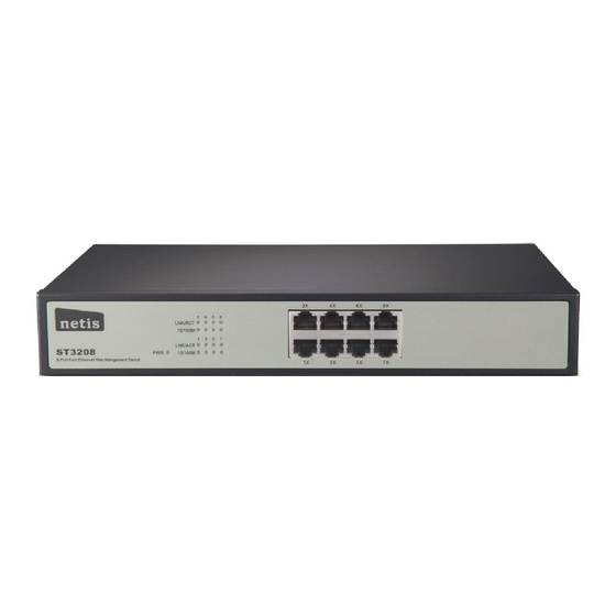
Technical Specifications For simplicity, we take ST3208 as an example of the product images below. The ST3208 front panel has 8 10/100M adaptive UTP ports, and the LED indicator. The 8 ports support 10/100Mbps bandwidth connection device, auto-negotiation capability. Each port... -
Page 5: Chapter 2: Mounting Device
Chapter3: Login The Device You can use the web browser-based configuration to manage ST3208. ST3208 to be configured through a web browser, at least a reasonable allocation of computer through an Ethernet connection to ST3208. -
Page 6: Configure The Computer
in the same network segment: 192.168.2. *** (1 <*** <255, *** is not equal to 11). Reference to the following steps to set up: 3.1 configure the computer The Management switch is managed via WEB pages. The smart and friendly interfaces make the switch management an easy job. - Page 7 Figure 3-1-2 3.Click ”network connections”. Figure 3-1-3 4.click right-hand button on the adapter icon and click “Properties”.
- Page 8 Figure 3-1-4 5.Double-click “Internet Protocol (TCP/IP)”. Figure 3-1-5 6.Use the following IP address: enter the IP address 192.168.2. *** (1 <*** <255, *** does not equal 11,because the default IP address of the switch is 192.168.2.11) , subnetmask 255.255.255.0, default gateway and preferred DNS server is optional and then click OK to close the Internet Protocol (TCP / IP) properties window.
-
Page 9: Windows 7/Windows Vista
Figure 3-1-6 7.Click “OK” and Close the Local Area Connection Properties window. Figure 3-1-7 3.1.2 Windows 7/Windows Vista Follow these steps to configure your computer 1、Start-Control Panel... - Page 10 Figure 3-1-8 2、Click “Network and Internet ” Figure 3-1-9 3、Click “Change adapter settings”...
- Page 11 Figure 3-1-10 4. Click right-hand button on the adapter icon and click “Properties” Figure 3-1-11 5.Double click “Internet protocol Version 4(TCP/IPv4)” Figure 3-1-12 5、Use the following IP address: enter the IP address 192.168.2. *** (1 <*** <255, *** does not equal 11, because the default IP address of the switch is 192.168.2.11) , subnetmask 255.255.255.0, default gateway and preferred DNS server is optional and then click OK to close the Internet Protocol (TCP / IP) properties window.
-
Page 12: Check The Connection
After setting the TCP / IP protocol, you can use the Ping command to verify whether the computer can communicate with ST3208. To perform a ping command, open a command window, the IP address in the command prompt where the Ping ST3208... -
Page 13: Login The Device
If the command window return to something like the following: Figure 3-2-1 Then Connection between ST3208 and computer is successful If the computer failed to connect on of ST3208, the command window will return the following content. Figure 3-2-2 Then make sure that your computer's network settings are correct and the cable is intact. -
Page 14: Functional Overview
3.4 Functional Overview The ST3208 switch have rich feature ,including the functions of system management, Port Management, Redundancy management, Security management , QoS management, Network Analysis, next chapter will introduce you these functions. -
Page 15: Chapter4: System
Chapter4: System 4.1 The Home page After logging into the switch, the main page appears as the following. It contains three parts: Figure 4-1-1 zone"1":The Port table lies at the top of the page. It provides a visual representation of the ports. -
Page 16: Ip Address
have basic information, including: Information, IP Address, User Account, Port Setting. The following picture is the detailed description. Figure 4-2-1 The System Information shows the system information of the switch, such as Device Type, MAC address, IP Address, Hardware and Software version information. 4.2.1 IP Address Figure 4-2-2... -
Page 17: User Account
On this page you can manually set the IP address, subnet mask, gateway and other information; can also use your network, among other DHCP SERVER switch automatically assigns an IP address. The switch default IP address is: 192.168.2.11 default subnet mask: 255.255.255.0 Default Gateway: no. -
Page 18: Port Setting
Notes: After modifying the password with immediate effect, the parameters will not be lost though is powered off. 4.2.3 Port Setting Figure 4-2-4 On this page, you can configure the basic parameter for the ports .When the port is disabled, the packers on the port will be discard. -
Page 19: Vlan
Figure 4-3-1 Select an aggregation group number, then add port in the left form to the right form, that make port join into aggregation group. ST3208 has max 4 groups, and one aggregation group can support max 8 member ports. -
Page 20: Introduction To Vlan
Introduction to VLAN The traditional Ethernet is a broadcast network, where all hosts are in the same broadcast domain and connected with each other through hubs or switches. Hubs and switches, which are the basic network connection devices, have limited forwarding functions. ... -
Page 21: Vlan Configure
Improving LAN security. By assigning user groups to different VLANs, you can isolate them at Layer 2. To enable communication between VLANs, routers or Layer 3 switches are required. Flexible virtual workgroup creation. As users from the same workgroup can be assigned to the same VLAN regardless of their physical locations, network construction and maintenance is much easier and more flexible. - Page 22 Figure 4-3-4 2. Choose the menu Configuration →VLAN →802.1Q PVID to load the following page. Configure PVID on this page. Figure 4-3-5 1). Select the desired port which to set PVID. Here is port 2 e.g. 2). Specify the PVID number of this port. Here is VLAN 2 e.g. 3).
- Page 23 Figure 4-3-6 1). Specify the VLAN ID need to configure. Here is VLAN 2 e.g. 2). Specify the VLAN Name of VLAN 2.Here is VLAN2. 3). Select the member port of VLAN 2, and frame type supported: Untagged or Tagged. Select port 2 as Untagged.
-
Page 24: Priority Mode
Figure 4-3-7 This switch classifies the ingress packets, maps the packets to different priority queues and then forwards the packets according to specified scheduling algorithms to implement QoS function. Traffic classification: Identifies packets conforming to certain characters according to certain rules. -
Page 25: Schedule Mode
Schedule Mode When the network is congested, the problem that many packets compete for resources must be solved, usually in the way of queue scheduling. The switch implements four scheduling queues. SP-Mode: Strict-Priority Mode. In this mode, the queue with higher priority will occupy the whole bandwidth. -
Page 26: Loop Prevention
4.3.4 Loop Prevention Figure 4-3-9 With loop prevention feature enabled, the switch can prevention loops using loop-prevention packets. When a loop is detected, the switch will display an alert or further block the corresponding port according to the port configuration. Choose the menu Configuration →Loop Prevention →... -
Page 27: Port-Based Mirroring
4.3.5 Port-based Mirroring Port mirroring allows you to duplicate the packets passing specified ports to the destination mirroring port. As destination mirroring ports usually have data monitoring devices connected to them, you can analyze the packets duplicated to the destination mirroring port on these devices so as to monitor and troubleshoot the network. -
Page 28: Bandwidth Control
you with more secure and flexible networking schemes. Choose the menu Configuration→ Port Isolation to load the following page. Figure 4-3-12 On the current device: Currently, only one isolation group is supported on a device, which is created automatically by the system as isolation group. -
Page 29: Jumbo Frame
Figure 4-3-13 If you select port to set ingress/egress rate, the system will automatically select integral multiple of 16Kbps that closest to the rate you entered as the real ingress/egress rate. Ingress: Configure the bandwidth for receiving packets on the port. You can select a port to set Ingress rate, the system will automatically select integral multiple of 16Kbps that closest to the rate you entered as the real Ingress rate. -
Page 30: Mac Constraint
Figure 4-3-14 You can set the length of jumbo frames that can pass through all the Ethernet ports. By default, the device allows jumbo frames with the length of 1522/1536/1552/2048 bytes to pass through all Ethernet ports. 4.3.9 MAC Constraint MAC address learning capability, you can setting of maximum number of MAC addresses that can be learned on the port Forwarding of frames with unknown destination MAC addresses after the upper limit of the MAC address table is reached. -
Page 31: Igmp Snooping
Figure 4-3-15 4.3.10 IGMP Snooping Internet Group Management Protocol Snooping (IGMP Snooping) is a multicast constraining mechanism that runs on Layer 2 devices to manage and control multicast groups. The switch, running IGMP Snooping, listens to the IGMP messages transmitted between the host and the router, and tracks the IGMP messages and the registered port. - Page 32 Figure 4-3-16 Unknown multicast data refers to multicast data for which no entries exist in the IGMP Snooping forwarding table. When the switch receives such multicast traffic: With the function of dropping unknown multicast data, the switch drops all the unknown ...
-
Page 33: Security
Figure 4-3-17 4.4 Security 4.4.1 MAC Address A switch maintains a MAC address table for frame forwarding. Each entry in this table contains the MAC address of a connected device, to which port this device is connected and to which VLAN the port belongs. -
Page 34: Mac Binding
Figure 4-3-18 Find Allows the user to move to a sector of the database corresponding to a user defined port, VLAN, or MAC address. The VLAN ID of the VLAN the port is a member of. MAC Address The MAC address entered into the address table. Port The port that the MAC address above corresponds to. -
Page 35: Storm Control Setting
Figure 4-3-19 4.4.2 Storm Control Setting Storm Control function allows the switch to filter Broadcast, Multicast and Unknown Unicast frame in the network. If the transmission rate of the three kind packets exceeds the set bandwidth, the packets will be automatically discarded to avoid network broadcast storm. Choose the menu Security→Storm Control to load the following page. -
Page 36: Monitoring
Figure 4-3-20 Storm control is used to stop broadcast, multicast or ARP request storms that may result when a loop is created. The Destination Look Up Failure control is a method of shutting down a loop when a storm is formed because a MAC address cannot be located in the Switch’s forwarding database and it must send a packet to all ports or all ports on a VLAN. -
Page 37: Backup Configuration
Figure 4-3-21 4.6 Tools 4.6.1 Backup Configuration On this page you can download the current configuration and save it as a file to your computer for your future configuration restore. On this page you can upload a backup configuration file to restore your switch to this previous configuration. - Page 38 Figure 4-3-22 Click the Backup button to save the current configuration as a file to your computer. You are suggested to take this measure before upgrading. Click the Restore button to restore the backup configuration file. It will take effect after the switch automatically reboots.
-
Page 39: Save Configuration
Figure 4-3-23 4.6.3 Save Configuration When the switch is saved configuration, the settings will be immediately applied to the switching software in RAM, and will immediately take effect. Choose the menu Tools→ Save Configuration to load the following page. -
Page 40: Load Factory Default
Figure 4-3-24 Click the save button, which can make parameters to be saved, your configuration will still work after restart. 4.6.4 Load Factory Default On this page you can reset the switch to the default. All the settings will be cleared after the switch is reset. - Page 41 4.6.5 Load Factory Default The switch system can be upgraded via the Web management page. To upgrade the system is to get more functions and better performance. Go to http://http://www.netis-systems.com/ to download the updated firmware. Choose the menu Tools→ Firmware Upgrade to load the following page.
- Page 42 Figure 4-3-26 Don’t interrupt the upgrade, to avoid damage, please don't turn off the device while upgrading.
Need help?
Do you have a question about the ST3208 and is the answer not in the manual?
Questions and answers