
Related Manuals for Testomat 2000 SO3 2-


Summary of Contents for Testomat 2000 SO3 2-
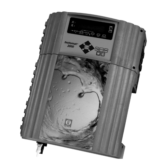
- Page 1 ® TESTOMAT 2000 SO Process Photometer for Sulphite 0 - 20mg/l Operating Instructions...
- Page 2 Service instructions …………………………… 21 Time setting ……………………………………… 12 Monitoring/Calibration with standard ……… 22 ® Limit value monitoring …………………………… 12 Spare parts list Testomat 2000 SO ……… 23 Hysteresis ……………………………………… 13 Logic functions ……………………………………… 13 Technical appendix …………………………… 24 Function IN1 ………………………………………...
-
Page 3: Introduction
(interface SK910, Art. No. 270305) with a dotted or continuous line printer (0/4-20mA). ® Trouble-free operation of the Testomat 2000 SO units is only guaranteed when using the HEYL ®... -
Page 4: Handling Instructions
Electrical load capacity • The maximum electrical load capacity of the relay outputs and the total power rating should never be exceeded. • ® Only use the Testomat 2000 SO for its intended purpose. • Environmental protection regulations •... -
Page 5: Installation And Commissioning
Lower water temperatures can cause mist to form on the sight-glass windows. ® For temperatures above 40 ° C the KCN type cooler should be installed in the branch line of the Testomat 2000 SO Hot water can scald you! ®... -
Page 6: Water Outlet
Water outlet The feed water flows through the measuring chamber to the drain via the outlet pipe (hose connection internal diameter 14 mm). Make sure, e.g. by using an open funnel, that the water drains off freely and backwater to the measuring chamber does not develop. -
Page 7: General Description
General description Internal construction 5 / 24... -
Page 8: Description Of The Electrical Connections
Description of the electrical connections Terminal block identification IN = input, OUT = output Terminal Type Function Comment Mains – Protective earth (5 x) Only with mains 115 / 230 V ! Mains, N = Neutral Mains input Mains, L = Live 230 - 240 V AC Neutral, switched (8 x) Mains voltage, max. -
Page 9: Description Of Display And Operating Features
STANDBY = manual analysis stop/standby Status display "Alarm" = confirms an alarm message Six LEDs signal the current status (analysis ® and unit status) of the Testomat 2000 SO i-key Call-up all unit information (also see i menu). Programming keys... -
Page 10: Status Displays
Immediately before each analysis the external flush valve is opened for the programmed period allowing the line up to ® the Testomat 2000 SO to fill with measuring water. Please ensure that the programmed flush time is sufficient. -
Page 11: Aux Programmable Function Output
AUX programmable function output The functioning of this volt-free relay output is programmable: 1. For contact prior to an analysis, e.g. to switch on a cooler "M" BASIC PROGRAM PROGRAM VALUES FUNCTION AUX CONTACT PRIOR TO ANALYSIS and/or 2. -
Page 12: Description Of The Signal Inputs And Outputs
Description of the signal inputs and outputs Only connect the signal inputs "Start", "Stop", "IN1" and "IN2" with volt-free contacts! Start external analysis start Stop external analysis stop Function Type of contact Test time Action Start normally open none In EXTERNAL operating mode an external analysis start volt-free! analysis is started by triggering a contact... -
Page 13: Function Characteristics
The device has a measuring range 0-20mg/l with two resolution ranges 0-9.9mg/l and 10-20mg/l. Measuring points The Testomat 2000 SO can be used for monitoring 2 measuring points. Measuring MEASURING POINTS L L L LM M M M M E... -
Page 14: Time Setting
"Flush” outlet. The external flushing time for the valve depends, just as the ® flushing time for unit flushing does, on the length and diameter of the supply line to the Testomat 2000 SO... -
Page 15: Hysteresis
Hysteresis HYSTERESIS LV1 L L L LM M M M M E Analysis (1,2,3) The respective limit value output only switches after the 1st, 2nd or 3rd limit value has been exceeded (suppression of the first or the second measured value). This increases the reliability of the analysis evaluation, e.g. -
Page 16: Alarm / Message
MAINTENANCE INTERV. LM M E Observance of the maintenance intervals is monitored and displayed by the ® 001d Testomat 2000 SO . Program the desired maintenance interval in days here. ( 0 days equals no maintenance interval. ) 14 / 24... -
Page 17: Interfaces (Optional)
For faults and when using very long cables (approx. 20 m) a screened cable should be used if possible. Serial interface RS232 ® The Testomat 2000 SO can also be connected to a log printer via the serial interface RS232 to enable the printout of measuring results and error messages. -
Page 18: Information Menu "I
Information menu "i" S u l f i t 0 - 20 4 lines are displayed M1: 0.6 mg/ltr (black scale) ^1: 1.0 mg/ltr ^2: 5.0 mg/ltr Structure of the "i" menu In the information menu it is possible to i button request active settings and statuses of the unit, the error history, the date for the... -
Page 19: Program Menu "M
Program menu "M" PROGRAM MENU S u l f i t 0 - 20 Testomat 2000 SO M1: 2.6 mg/l BASIC PROGRAM Call: (1) ^1: 3.0 mg/l ^2: 5.0 mg/l Use the "M" key to open the program menu "M". -
Page 20: Date/Time
Date/Time (12) Set the time and date by selecting and activating the desired function via the arrow keys and the "ENTER” key. Subsequently press the "M" key again to save the setting and to return to the display function. Basic program This menu item can only be accessed after entering the password! Example for password entry: >BASIC PROGRAM... -
Page 21: Structure Of The Basic Program
Structure of the basic program MODE OF OPERATION L L L L M M M M M E VOLUME INTERVAL L L L L M M M M M E PROGRAM MENU Testomat 2000 SO TIME-CONTROLLED 000l BASIC PROGRAM Volume interval External (START) -
Page 22: Error Messages / Troubleshooting
Error messages / Troubleshooting Displayed message Unit result functions Possible causes Remedies (flashes at selected display) Ff. POWER FAILURE 24 V - After programming: • Internal power failure of the Replace fuse F4 or F8 Continuous alarm or 24 V supply (The control lamp "Power"... -
Page 23: Further Information
1. Switch off the unit or press the "STANDBY" key (measuring chamber completely drained?). ® 2. Close the manually-operated valve of the branch line to the Testomat 2000 SO 3. Unhook the toggle type fastener, tip the measuring chamber upwards and remove it. - Page 24 After the outlet valve is closed (LED “OUT” is OFF), fill the chamber again (LED “IN” lights up). The water level inside the chamber sinks to the sample volume level. ® Analysis is running and at least the calibration factor will be calculated by the Testomat 2000 22 / 24...
- Page 25 ® Spare parts list Testomat 2000 SO Art. no. Pressure controller Art. No. Unit spare parts list 040120 Controller / filter receiver 031582 Fuse M4A 040129 Controller plug T2000, complete 037236 Base circuit board T2000, complete 230V 011225 Flow controller valve body (1 - 8 bar)
-
Page 26: Technical Appendix
Technical appendix ® Block diagram Testomat 2000 SO Technical data Power supply: 230 V or 24 V ± 10 %, 50 - 60 Hz, fuse M4A Unit protection: 230 V: T0.1A 24 V: T1.0A The unit is non volatile Power consumption: max.
Need help?
Do you have a question about the 2000 SO3 2- and is the answer not in the manual?
Questions and answers