
Related Manuals for Lapis Roll Laminator PL-LR

Summary of Contents for Lapis Roll Laminator PL-LR
- Page 1 Drucktechnologie GmbH User Manual Passport-Laminator Lapis Drucktechnologie GmbH Weinheimerstr. 62 68309 Mannheim Tel.: +49(0)621/7363866 Fax.: +49(0)621/7363868 Version: S20/V3.42 Email: info@lapis-online.de...
- Page 3 Table of contents 1. General information............5 Product description..............5 Symbols and conventions............6 Intended use................ 6 Safety information..............6 Environmental information............7 2. Connection and commissioning.......... 9 Device overview..............9 Unpacking and setting up the device........10 Mounting the feed table............10 Connecting the device............
- Page 4 6. Troubleshooting..............37 Types of errors and elimination..........37 Error messages..............38 7. Service................41 Firmware upgrade..............41 AVR programming protocol............. 42 8. Certifications..............45 EG-Konformitätserklärung............45 Safety Standard FCC.............. 46 EMC Zertifikat............... 47...
-
Page 5: General Information
General information Product description The passport laminator laminates all pages of the passport including the inside of the cover. A wafer-thin holographic film is applied to the paper surface via a temperature-controlled heated roller. The laminator can be integrated into an automatic personalisation system or can function as an independent station. -
Page 6: Intended Use
Intended use The device is constructed in accordance with the latest engineering practice and per the recognised safety regulations. Nevertheless, danger to the life and limb of the user or third parties or damage to the device and other property may occur when using it. -
Page 7: Environmental Information
When opening the housing cover a risk of death exists due to live parts. Environmental information The device comprises materials that can be reused when processed by specialist recycling companies. The optimum design of the laminator facilitates a straightforward separation of the recyclable materials. Label the device as scrap and dispose of it in accordance with the legal regulations... -
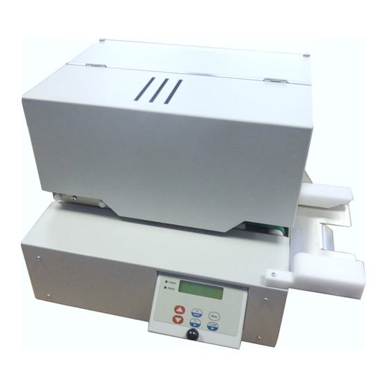
Page 9: Connection And Commissioning
Connection and commissioning Device overview Lock Cover hood Feed table Control panel Spacer ring Rocker for passport infeed RFID module Heated roller interlocking Carrier roller Heated roller Safety guard for heated roller... -
Page 10: Unpacking And Setting Up The Device
Unpacking and setting up the device • Remove the device from its packaging and place on a level surface. • Check the laminator for transport damage. • Check delivery for completeness. Scope of supply: • Passport laminator • Mains cable •... -
Page 11: Connecting The Device
Connecting the device Mains switch Mains fuse 2A slow blow Mains connection jack RS232 interface Connecting to the power supply The laminator is equipped with a broad-range power pack for a mains voltage of 100 V to 240 V. • Ensure that the device is switched off. -
Page 12: Inserting Film
Inserting film There is a risk of burning on the safety guard for the heated roller (5) Newly inserted patch film must be subsequently synchronised. This is not necessary in the case of holographic film without an index mark. The process therefore differs very slightly. -
Page 13: Inserting A Document
When inserting or exchanging holographic film without an index mark proceed as follows: • Open housing cover, if necessary unlock the lock first • Switch off the device and let it cool down • Release the heated roller interlocking. To do so push the lever (3) up. •... -
Page 15: The Control Panel
The control panel Control panel configuration The display informs the user of the current device status, reports errors and indicates configuration settings in the menu. The keys enable control functions, the accessing of information and navigation within the menu. If the device is switched on then the green LED illuminates. An error is additionally signalled via the red LED. -
Page 16: Key Functions In The Configuration Menu
Taste Funktion Displays the device no. and program version Deletes error messages CLEAR Switches to the configuration menu MENUE Key functions in the configuration menu The configuration menu offers setting options across multiple levels, in order to configure the laminator for the specific requirements. It is also equipped with test and service functions in order to support the configuration and function of the device. -
Page 17: Device Statuses
Device statuses Status Description After the switch-on process the laminator is in the Initialization initialisation phase and carrying out the self-test The laminator is in the heat-up phase -- HEATING -- The laminator is in the cool-down phase -- COOLING -- Ready The laminator is ready for operation in process... -
Page 19: Configuration
Configuration Configuration via control panel 1. Menu level 2. Menu level Access level Startmenü SETTING DEVICE FoilType Index=Yes Standby SETUP Loop With some firmware versions the button is to be replaced with MENUE Within the access level the user works in editing mode: Function Increases / reduces the value or changes an option Special functions for some parameters... - Page 20 Menu structure 1. Menu level 2. Menu level Access level Special function = Default value on Access level 180 ºC Temperature SETTING Test Lamination Speed 8 mm/s Delay Heatroller 200 ms Test Transport Speed 60 mm/s LaminationLength 125 mm FoilFurtherMove 35 mm Foil Position 0 x1/10mm...
-
Page 21: Configuration Via Interface
Configuration via interface The parameters accessible via the control panel can also be adjusted via the serial interface. Furthermore, there is an additional command for controlling the device. The laminator is connected by means of a standard cable RS-232 SERIAL SUB D9 connector jack to the computer. - Page 22 List of Commands SETTING COMMANDS Delay Heatroller Lamination Speed Transport Speed Lamination Length Foil Further Move Foil Position Temperature DEVICE COMMANDS K20;p Foil Type K40;p Standby K02;p Loop CONTROL COMMANDS Reset Alife-Status Status Open Retract Close Retract SYSTEM COMMANDS Clear Error Read Programm-Version Read Serial Number (Board) Read Serial Number (Device)
-
Page 23: Configuration Settings
Configuration settings The different setting options configure the laminator for specific requirements. This is carried out either via the control panel or via the interface by means of a command set. There are exceptions, whereby access is only possible via one or the other method. - Page 24 Menu: SETTING / Transport Speed Command: <ESC>Hd<CR> Setting the transport speed of the document outside of lamination. In order to carry out a test it is possible to start the motor via Setting range: 40...60...80 mm/s Menu: SETTING / Lamination Length Command: <ESC>Ld<CR>...
- Page 25 DEVICE Menu: DEVICE / Foil Type Command: <ESC>K20;p<CR> Setting the film type. Setting range: 0 = ohne Indexmarke 1 = mit Indexmarke Menu: DEVICE / Standby Command: <ESC>K40;p<CR> If the laminator is not used for 30 minutes it switches to energy-saving mode. The temperature of the heated roller drops in this mode.
- Page 26 Menu: DEVICE / Operation Mode The laminator operates in 3 different modes. 2 of these are exclusively suitable for test purposes. Setting range: Normal Test: Hoff Test: PassThrough The standard setting is "normal" and reflects normal operation. "Test: Hoff" also reflects the normal operating process, although the heating is off in this case.
- Page 27 Menü: DEVICE / Admin Password DEVICE / User Password In factory state the password protection is inactive (password = 0000). If you activate a password protection, the user must enter a password to start the laminator after power on. The Administration-Access without restriction allows input option of a user password with menu lock.
- Page 28 SETUP Menu: SETUP / Pass Position Stipulation of the passport position at the heated roller. This is optimally set in the factory and does not require adjustment. Setting range: 120...216...360 x 1/24mm Menü: SETUP / Lami Length Corr Correction of lamination length in “Settings/LaminationLength”. Einstellbereich: 0...10...20 -10mm Menu:...
- Page 29 Menu: SETUP / Uref Step FP(mV) Indicates the motor current for the passport transport. It is optimally set in the factory and does not require adjustment. In order to carry out a test it is possible to start the motor via Setting range: 0...2500...5000 mV Menu:...
- Page 30 SENSORS Menü: SENSORS / Status Sensors Shows the actually Status of Sensors: 1 2 3 4 □ . . □ □ □ □ ■ ■ 1 Sensor LS1 Transport channel 1. Sensor to the right of for retract and pass position □...
- Page 31 Menu: SENSORS / Sensor LS1 (mV) Indicates the transmission current for the LS1 sensor. This must be set such that the reception current is shown as approx. 3500mV. The transmission current is aut. determined via . This value is optimally set in the factory and does not require adjustment.
-
Page 32: Test
Test Menu: TEST / DC re-coiler Test of the DC film winder. The The film winder rotates forwards, so that the film is wound on. The film winder rotates backwards, so that the film is wound off. Menu: TEST / DC re-coiler Test of the DC film unwinder: The film unwinder rotates forwards, so that the film is wound off. -
Page 33: System
System Function: Clear Error Startmenu: CLEAR Command: <ESC>!c<CR> Deletes error messages, refer also to the "trouble-shooting" chapter. Function: Read Programm-Version Startmenu: Command: <ESC>!v<CR> Reads the firmware version. Is shown in line 1 on the display. As a response following a command transfer the user receives a sequence in the form e.g. - Page 34 Function: Firmware Upgrade Command: <ESC>U<CR> Calls up the bootloader to upgrade the firmware in flash. The protocol description is located in the attachment. Function: Storage of Macro Menu: SAVE Command: <ESC>S<CR> All configuration parameters are stored in the EEPROM so that these values are not lost after the switch-off process.
-
Page 35: Control
Control Control commands Reset Command: <ESC>!!<CR> The laminator is reset. The process equates to a restart after a Power On. Settings that are not saved in the macro are lost. Open rocker Befehl: <ESC>W0<CR> Manual opening of the rocker. Close rocker Command: <ESC>W1<CR>... -
Page 36: Status Query
Status query Function: Status Command: <ESC>!f<CR> Delivers detailed information on the current status of the laminator. The status can be requested at any time. The response consists of 7 Bytes. Format: =hh/dd<CR> hh: Statuscode Hint: 00: READY Device is ready for work 01: WAIT Temperature of heat roller too high / too low 02: BUSY... -
Page 37: Troubleshooting
Troubleshooting Types of errors and elimination If an error occurs then this is signalled by the red ERROR LED whilst the error message is shown on the display. Different error codes indicate the cause of the problem. In a normal case it is possible to delete the error message after eliminating the problem with after which the device is once again ready for CLEAR... -
Page 38: Error Messages
Error messages Error message Cause Remedy Identification or ID does not Reinsert previous film or restart #52 Tag verify match with the initial version laminator. of the film. Film was probably exchanged after restart. Invalid tag information with Use permissible / approved film #53 Tag invalid initial acquisition of the film. - Page 39 Error message Cause Remedy No film transport. Check film #67 ribbon trans No response from tag reader. Check tag reader. #81 RFID no data Contact service! Impermissible ADU values Check temperature sensor. #82 ADC problem Contact service! No temperature increase to Check temperature sensor.
-
Page 41: Service
Service Firmware upgrade For service purposes the laminator is connected with the computer via the serial interface. A standard cable RS-232 SERIAL SUB D9 connector jack is used. After starting the Windows application AVR-Bootloader it is possible to load new firmware. -
Page 42: Avr Programming Protocol
AVR Programming Protocol The upgrade process can also be started without Windows software via the sequence <ESC>U<CR>. The subsequent protocol must then be carried out independently: Laminator Host Hint ˆ BootLoader is ready @&$ Start Download Sequence V1.31 ready for Download enable Interface :naatddd…c Send 1 HexLine (Intel-Hex-Format) - Page 43 The programming software continues sending the hex file until it is all sent. After each line of “.hex” file is received by the bootloader, one of three characters is transmitted by the bootloader: - ‘~’ Line received with no errors. - ‘%’Line received with no error, but an error occurred while flashing.
-
Page 45: Certifications
Certifications...
Need help?
Do you have a question about the Roll Laminator PL-LR and is the answer not in the manual?
Questions and answers