Sign In
Upload
Download
Table of Contents
Contents
Add to my manuals
Delete from my manuals
Share
URL of this page:
HTML Link:
Bookmark this page
Add
Manual will be automatically added to "My Manuals"
Print this page
×
Bookmark added
×
Added to my manuals
Manuals
Brands
Finn-Power Manuals
Power Tool
E5x
User manual
Finn-Power E5x User Manual
Turret punch press e series
Hide thumbs
1
2
3
4
5
6
7
8
9
10
11
12
13
14
15
16
17
18
19
20
21
22
23
24
25
26
27
28
29
30
31
32
33
34
35
36
37
38
39
40
41
42
43
44
45
46
47
48
Table Of Contents
49
page
of
49
Go
/
49
Contents
Table of Contents
Bookmarks
Table of Contents
Introduction
Safety Instructions
Safety Symbols
Safety During Operation and Maintenance
Safety Devices and Functions of the Base Machine
Periodic Inspection of Safety Devices
Emergency Stop Buttons and Turret Service Door
Hydraulic and Pneumatic System
Technical Information, E5/E6/E8
Notes on Technical Information
Operating Description of Turret Punch Press
Main Structure of the Machine E5
Turret
Clamps
Punching Mechanism, E Machines
Clamp Protection Areas
Control Desk (Siemens)
Control Panel (Siemens)
Remote Control Panel
Using the Machine
Production Order Run
Production Run Control
Shutting down the Machine in a Normal Situation
Mounting a Tool on the Turret
Operating Modes
MDA and AUTOMATIC Modes
Program Control Buttons and Function Keys
Preventive Maintenance
E5 Maintenance Points
E5/E6/E8 Monthly Maintenance
Recommended Lubricants
Multi-Tool Tool Station (Option)
Additional Clamp (Option)
SU3/SU6C/SU9 Sorting Unit (Option)
Control Panel
Automatic Mode
Advertisement
Quick Links
1
Introduction
2
Technical Information, E5/E6/E8
3
Turret
Download this manual
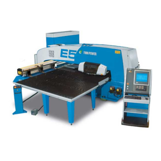
USER GUIDE
E5 TURRET PUNCH PRESS
Series
12.2
Control
Siemens 840D
Revision/Date 2/2009-10-22
Table of
Contents
Previous
Page
Next
Page
1
2
3
4
5
Advertisement
Table of Contents
Need help?
Do you have a question about the E5x and is the answer not in the manual?
Ask a question
Questions and answers
Related Manuals for Finn-Power E5x
Power Tool Finn-Power E6 User Manual
Turret punch press e series (49 pages)
This manual is also suitable for:
E5
E6
E8
Table of Contents
Save PDF
Print
Rename the bookmark
Delete bookmark?
Delete from my manuals?
Login
Sign In
OR
Sign in with Facebook
Sign in with Google
Upload manual
Upload from disk
Upload from URL


Need help?
Do you have a question about the E5x and is the answer not in the manual?
Questions and answers