Table of Contents
Advertisement
Quick Links
Operating and Technical Manual
Operating and Technical Manual
Operating and Technical Manual
Operating and Technical Manual
UHF B IV-V RF LIQUID-COOLED POWER AMPLIFIER
UHF B IV-V RF LIQUID-COOLED POWER AMPLIFIER
UHF B IV-V RF LIQUID-COOLED POWER AMPLIFIER
UHF B IV-V RF LIQUID-COOLED POWER AMPLIFIER
Oct 2013
Rev. 004
ETL0W474G
ETL0W474G
ETL0W474G
ETL0W474G
750 W (RMS) DTV / 1800 W ATV
750 W (RMS) DTV / 1800 W ATV
750 W (RMS) DTV / 1800 W ATV
750 W (RMS) DTV / 1800 W ATV
EuroTel S.p.A.
Via Martiri della Libertà, 4
20035 Lissone (MI), Italy
Tel. +39 039 24361 – Fax +39 039 2436222
E-Mail
sales@eurotel.it
CMAN0W474G
– Web
http://www.eurotel.it
ETL0W474G
Page 1 1 1 1
Advertisement
Table of Contents

Related Manuals for EuroTel ETL0W474G

Summary of Contents for EuroTel ETL0W474G
- Page 1 Rev. 004 ETL0W474G Operating and Technical Manual Operating and Technical Manual Operating and Technical Manual Operating and Technical Manual ETL0W474G ETL0W474G ETL0W474G ETL0W474G 750 W (RMS) DTV / 1800 W ATV 750 W (RMS) DTV / 1800 W ATV 750 W (RMS) DTV / 1800 W ATV...
- Page 2 ETL0W474G Rev. 004 Page 2 CMAN0W474G Oct 2013...
- Page 3 3 ) Output Parameters......................10 4 ) Dimensions and Weight....................10 IV - FUNCTIONAL DESCRIPTION.....................11 1 ) Theory of operation of UHF RF Amplifier ETL0W474G series.........11 Section D- INSTALLATION AND OPERATING INFORMATION.............13 I - INSTALLATION........................13 1 ) Series ETL0W474G R. F. Amplifier: mounting procedure..........13 2 ) Other connections.......................13...
- Page 4 TABLE OF ILLUSTRATIONS TABLE OF ILLUSTRATIONS TABLE OF ILLUSTRATIONS Figure 1: UHF TV RF Power Amplifier series ETL0W474G, blocks diagram.......12 Figure 2: Front panel of series ETLW0474G TV RF Amplifier............15 Figure 3: Rear panel of series ETL0W474G TV RF Amplifier............17 Figure 4: Enable socket and connector..................18...
-
Page 5: Section A- General Information
© EUROTEL S.p.A. © EUROTEL S.p.A. The information contained herein is the property of EUROTEL S.p.A. and is supplied without liability The information contained herein is the property of EUROTEL S.p.A. and is supplied without liability The information contained herein is the property of EUROTEL S.p.A. and is supplied without liability The information contained herein is the property of EUROTEL S.p.A. -
Page 6: Section B- Safety Instructions
ETL0W474G Rev. 004 Section B-SAFETY INSTRUCTIONS Section B- SAFETY INSTRUCTIONS Section B- Section B- SAFETY INSTRUCTIONS SAFETY INSTRUCTIONS 1 ) GENERAL INSTRUCTIONS GENERAL INSTRUCTIONS GENERAL INSTRUCTIONS GENERAL INSTRUCTIONS Observe the following safety precautions when handling this unit. This equipment operates with dangerous voltages and currents. -
Page 7: R.f. Hazards
Rev. 004 ETL0W474G 3 ) R.F. HAZARDS R.F. HAZARDS R.F. HAZARDS R.F. HAZARDS In the amplifier, high-energy R.F. circuits are fed through common R.F. connectors (eg N). Depending on the output power, the amplifier outputs are fitted with screw-in R.F. lines or waveguides. -
Page 8: Emergency Resuscitation: Expired Air Method
ETL0W474G Rev. 004 7 ) EMERGENCY RESUSCITATION: EXPIRED AIR METHOD EMERGENCY RESUSCITATION: EXPIRED AIR METHOD EMERGENCY RESUSCITATION: EXPIRED AIR METHOD EMERGENCY RESUSCITATION: EXPIRED AIR METHOD If possible, lie the victim on his back, with his head slightly higher than his feet. Clear the mouth and the throat of any obvious obstruction. -
Page 9: I - Introduction
This involves an efficiently use and a longer lifetime of the system. • An additional fan is included in the case of ETL0W474G to create an airflow within the case to dissipate any residual heat. •... -
Page 10: Iii - Technical Specifications
ETL0W474G Rev. 004 III - TECHNICAL SPECIFICATIONS III - TECHNICAL SPECIFICATIONS III - III - TECHNICAL SPECIFICATIONS TECHNICAL SPECIFICATIONS 1 ) General General General General Primary power 57 V Tri-phase ±15%. Frequency: 47 to 60 Hz Consumption (channel frequency 800 MHz): ATV 3800 W @ 50% A.P.L. -
Page 11: Iv - Functional Description
• On module ETL0W474G an ALC control signal manages the output power of the amplifier in order to keep constant its value. This ALC reference level is set directly on the module via the control button on the front panel. -
Page 12: Figure 1: Uhf Tv Rf Power Amplifier Series Etl0W474G, Blocks Diagram
ETL0W474G Rev. 004 Figure 1: UHF TV RF Power Amplifier series ETL0W474G, blocks diagram Page 12 CMAN0W474G Oct 2013... -
Page 13: I - Installation
I - I - I - I - INSTALLATION INSTALLATION INSTALLATION INSTALLATION The series ETL0W474G TV RF Amplifier is assembled in a 3U drawer that can be mounted in a 19 inch standard rack. 1 ) Series Series Series ETL0W474G R. F. Amplifier: mounting procedure Series ETL0W474G R. -
Page 14: Series Etl0W474G: Front Panel Controls, Displays & Connectors
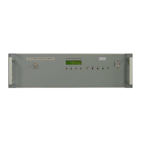
ETL0W474G: front panel controls, displays & connectors ETL0W474G: front panel controls, displays & connectors The front panel of the series ETL0W474G TV RF AMPLIFIER is shown in Figure 2. The controls, displays and connectors on the front panel are as follows:... -
Page 15: Figure 2: Front Panel Of Series Etlw0474G Tv Rf Amplifier
Rev. 004 ETL0W474G Figure 2: Front panel of series ETLW0474G TV RF Amplifier Oct 2013 CMAN0W474G Page 15... -
Page 16: Series Etl0W474G: Rear Panel Connectors
Series Series ETL0W474G: rear panel connectors ETL0W474G: rear panel connectors The rear panel of the series ETL0W474G TV RF AMPLIFIER is shown in Figure 3. The connectors on the rear panel are as follows: REAR PANEL REAR PANEL REAR PANEL... -
Page 17: Figure 3: Rear Panel Of Series Etl0W474G Tv Rf Amplifier
Rev. 004 ETL0W474G Figure 3: Rear panel of series ETL0W474G TV RF Amplifier Oct 2013 CMAN0W474G Page 17... -
Page 18: Enable In/Out Din Socket
ETL0W474G Rev. 004 5 ) Enable IN/OUT DIN socket Enable IN/OUT DIN socket Enable IN/OUT DIN socket Enable IN/OUT DIN socket Figure 4: Enable socket and connector Socket seen from back panel of equipment This socket is used: • To enable the Amplifier with an external command. -
Page 19: Serial Data Rs-485 Socket
Rev. 004 ETL0W474G 7 ) SERIAL DATA RS-485 socket SERIAL DATA RS-485 socket SERIAL DATA RS-485 socket SERIAL DATA RS-485 socket Table 2: Connections to SERIAL DATA RS485 socket Figure 6: Serial DataRS485 in-out socket DESCRIPTION DESCRIPTION DESCRIPTION DESCRIPTION 1 1 1 1... -
Page 20: Data Communication
A serial port is available as output interface in RS-232 standard. • A serial port is available as output interface in RS-485 standard. • The Technical information manual for the installation and operation of the interface is available from EuroTel to EuroTel Customers on request. Page 20 CMAN0W474G Oct 2013... -
Page 21: Ii - Operating Procedures
1 ) First time operation of First time operation of First time operation of series First time operation of series series series ETL0W474G ETL0W474G ETL0W474G ETL0W474G • While keeping the Exciter turned off, turn the ON/OFF switch on the front panel of the rack cabinet to ON. -
Page 22: Etl0W474G: Changing The M.l.c. Nominal Value
ETL0W474G Rev. 004 2 ) ETL0W474G: changing the M.L.C. Nominal value ETL0W474G: changing the M.L.C. Nominal value ETL0W474G: changing the M.L.C. Nominal value ETL0W474G: changing the M.L.C. Nominal value This function changes the value of the input electronic attenuator in order to equalize the gain of the... - Page 23 Rev. 004 ETL0W474G 3 ) RF Amplifier RF Amplifier series series ETL0W474G: in case of difficulty ETL0W474G: in case of difficulty RF Amplifier RF Amplifier series series ETL0W474G: in case of difficulty ETL0W474G: in case of difficulty • Absence of RF power from the Amplifier often indicates that the unit is not enabled: in this case there is no reading at V supply 1, 2, 3 and 4.
-
Page 24: Iii - Series Etl0W474G - Multi-Function Metering Display
ETL0W474G Rev. 004 III - III - SERIES ETL0W474G - MULTI-FUNCTION METERING DISPLAY III - III - SERIES ETL0W474G - MULTI-FUNCTION METERING DISPLAY SERIES ETL0W474G - MULTI-FUNCTION METERING DISPLAY SERIES ETL0W474G - MULTI-FUNCTION METERING DISPLAY 1 ) Alphanumeric LCD display description... -
Page 25: First Level Menu Description
Rev. 004 ETL0W474G FWD drive = FWD drive = ..W ..W FWD drive = FWD drive = ..W ..W Shows the RF drive level in Watts to the final Amplifier stages. ALC ref = ALC ref =... - Page 26 ETL0W474G Rev. 004 ⇒ View alarms log View alarms log Shows the last alarm conditions occurred. View alarms log View alarms log ⇒ View alarms log + View alarms log + View alarms log + View alarms log + ⇒ View alarms log –...
- Page 27 Rev. 004 ETL0W474G ⇒ ALC refAv – ALC refAv – (only for DTV mode) Decrements average ALC refAv – ALC refAv – reference level. ⇒ ALC refPk + ALC refPk + (only for ATV mode) Increments peak ALC refPk + ALC refPk + reference level.
-
Page 28: Second Level Menu Description
ETL0W474G Rev. 004 3 ) Second level menu description Second level menu description Second level menu description Second level menu description To access to the second level menu, turn on the equipment while pushing the SELECT push button. In this way it will be possible to access all the first level menu plus other menu of second level. - Page 29 Rev. 004 ETL0W474G ⇒ Num. of netw ampl Num. of netw ampl Defines the number of amplifiers in the system. Num. of netw ampl Num. of netw ampl ⇒ No ext. amplifier No ext. amplifier Operates with no additional No ext. amplifier No ext.
- Page 30 ETL0W474G Rev. 004 ⇒ Lowpwr AvgTresh + Lowpwr AvgTresh + Lowpwr AvgTresh + Lowpwr AvgTresh + ⇒ Lowpwr AvgTresh - Lowpwr AvgTresh - Lowpwr AvgTresh - Lowpwr AvgTresh - ⇒ VSWR treshold ad VSWR treshold ad Adjusts the alarm threshold of peak reflected output...
- Page 31 Rev. 004 ETL0W474G ⇒ Load Rflpk tresh Load Rflpk tresh Not used. Load Rflpk tresh Load Rflpk tresh ⇒ Load Rflav tresh Load Rflav tresh Not used. Load Rflav tresh Load Rflav tresh ⇒ FWD coupler adj. FWD coupler adj.
-
Page 32: Alarm And Warning Events
WARNING EVENT: WARNING EVENT: Amplifier operation is not interrupted. The power supply of the final modules of the amplifier is reduced by about 13%. This reduces by about 25% the RF output power of the ETL0W474G Amplifier. ALARM EVENT: ALARM EVENT:... -
Page 33: Warning Led
“Low” threshold value is set to zero, restoring threshold value is the same of the warning threshold value. When a warning or an alarm event that has a threshold value configured occurs, this event is also reported on the lower row of ETL0W474G display. 5 ) Warning LED Warning LED... - Page 34 ETL0W474G Rev. 004 Page 34 CMAN0W474G Oct 2013...
-
Page 35: Section E- Layout Assembly And Circuit Diagrams
ETL0W474G Layout of R.F. parts of Amplifier ETL0W474G Layout of R.F. parts of Amplifier • This Section describes the layout of the R.F. parts & modules of the ETL0W474G Amplifier. Referring to the parts layout, the R.F. drive coming from the external Exciter, reaches driver module MOD1 through input socket DRIVER R.F. - Page 36 ETL0W474G Rev. 004 Page 36 CMAN0W474G Oct 2013...
- Page 38 Rev. 004 ETL0W474G Oct 2013 CMAN0W474G Page 37...
- Page 39 ETL0W474G Rev. 004 EuroTel S.p.A. Via Martiri della Libertà, 4 20035 Lissone (MI), Italy Tel. +39 039 24361 – Fax +39 039 2436222 E-Mail sales@eurotel.it – Web http://www.eurotel.it Page 38 CMAN0W474G Oct 2013...
Need help?
Do you have a question about the ETL0W474G and is the answer not in the manual?
Questions and answers