
Related Manuals for EuroTel ETL0480TBD

Summary of Contents for EuroTel ETL0480TBD
- Page 1 Technical Manual (INSTALLATION & USE) 1 kW UHF TV RF AMPLIFIER ETL0480TBD EuroTel S.r.l. Via della Birona 30/32 20052 Monza, Italy Tel. +39 039 230 2645 – Fax +39 039 230 2650 salesmail@eurotel.it http://www.eurotel.it E-Mail – Web...
-
Page 2: Table Of Contents
5 ) Dimensions and Weight ..................10 VI - FUNCTIONAL DESCRIPTION..................11 1 ) Theory of operation of 1 kW UHF RF Amplifier ETL0480TBD ........11 2 ) Theory of operation of 700 W UHF TV RF Amplifier Module ETL0470 ....... 12 VII - RF AMPLIFIER CONFIGURATIONS &... - Page 3 ETL0480TBD 2 ) ETL0480TBD – 1 kW – Replacing one RF Amplifier, simplified procedures....32 3 ) ETL0480TBD – 1 kW – Replacing one RF Amplifier, detailed procedure ....34 TABLE OF ILLUSTRATIONS Figure 1: ETL0480TBD-TP Transposer (Exciter + Amplifier)............7 Figure 2: UHF TV 700 W RF Power Amplifier Module ETL0470 ............
-
Page 4: Section A-General Information
DATE © EUROTEL S.r.l. The information contained herein is the property of EUROTEL S.r.l. and is supplied without liability for errors or omissions and no part may be reproduced, used or disclosed, except as authorized by contract or other written permission. The copyright and the foregoing restriction on reproduction, use and disclosure extends to all media in which this information may be embodied, including magnetic or electronic storage, etc. -
Page 5: Warnings
EUROTEL - ITALY ETL0480TBD III - WARNINGS • Observe safety precautions when handling this unit. This equipment operates with dangerous voltages and currents. • Always disconnect power before opening covers or removing any part or module of this unit. •... -
Page 6: Emergency Resuscitation: Expired Air Method
EUROTEL - ITALY ETL0480TBD 2 ) EMERGENCY RESUSCITATION: EXPIRED AIR METHOD • If possible, lie the victim on his back, with his head slightly higher than his feet. Clear the mouth and the throat of any obvious obstruction. • Kneel on one side of the victim, level with his head. LIFT THE JAW AND TILT THE HEAD BACK AS FAR AS POSSIBLE. -
Page 7: Section B-Purpose And Planning Information
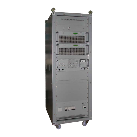
The configuration of two ETL0470 TV RF Power Amplifier Modules is designated model ETL0480TBD, which comprises two power amplifier modules, two 3 dB hybrids and a band-pass output filter with a power rating of 1 kW. All these components are housed in a standard 19” metal cabinet, which provides additional space for the Exciter and for ancillary equipment. -
Page 8: Composition Of Rf Amplifier Etl0480Tbd, 1 Kw Uhf
III - COMPOSITION OF RF AMPLIFIER ETL0480TBD, 1 kW UHF • RF Amplifier ETL0480TBD comprises two ETL0470 TV RF Power Amplifier Modules, one input power divider, one output RF power summer, 50 Ohm balancing load for the hybrid and one band-pass filter for the attenuation of harmonic and spurious products. -
Page 9: Composition Of Etl0470, Rf Amplifier Module 700 W Uhf
EUROTEL - ITALY ETL0480TBD IV - COMPOSITION OF ETL0470, RF AMPLIFIER MODULE 700 W UHF • The ETL0470 TV RF Power Amplifier Module consists of one class “AB” driver stage, that feeds four class “AB” final RF amplifiers combined. Other parts of this Amplifier are: three identical switch mode power supply modules, a microprocessor controlled metering, alarm and protection module, a directional coupler. -
Page 10: Technical Specifications
EUROTEL - ITALY ETL0480TBD V - TECHNICAL SPECIFICATIONS 1 ) General Primary power 400 V Tri-phase. +10% -15% 50 Hz, Consumption: 3k W @ 50% A.P.L. at 1 kW vision carrier power. Cooling Forced air. Operating temperature range -5°C to +45°C. -
Page 11: Transmission Quality
EUROTEL - ITALY ETL0480TBD > 60 dB (-6, -13, -17, -20) @ rated output power, with pre-correction inserted, system I with Nicam. 4 ) Transmission Quality (with driver series ETL0310) Vision weighted S/N ratio (CCIR 567) > 60 dB. Amplitude Frequency response ±... -
Page 12: Functional Description
EUROTEL - ITALY ETL0480TBD VI - FUNCTIONAL DESCRIPTION 1 ) Theory of operation of 1 kW UHF RF Amplifier ETL0480TBD • With reference to the general Blocks diagram, Figure 3, the output signal from the Exciter, at a nominal level of 4 W, reaches the low power, 3 dB hybrid, which splits the drive into 2 components of 2 W each. -
Page 13: Theory Of Operation Of 700 W Uhf Tv Rf Amplifier Module Etl0470
EUROTEL - ITALY ETL0480TBD • Even though the two tandem connected RF Amplifiers are perfectly symmetrical, by convention the RF Amplifier installed in the upper position in the cabinet is called MAIN AMPLIFIER (or N°1 Amplifier) while the one in the lower position is called the SLAVE AMPLIFIER (or N°2 Amplifier). -
Page 14: Figure 4: Etl0470 Rf Amplifier Blocks Diagram
EUROTEL - ITALY ETL0480TBD • Should a transistor of one of the RF output stages fail in short circuit, one supply will be shorted out (the supply will not fail in this condition) and the amplifier output, while dropping, will still be at an useful level of approximately 25% rated power. -
Page 15: Rf Amplifier Configurations & Ordering Information
EUROTEL - ITALY ETL0480TBD VII - RF AMPLIFIER CONFIGURATIONS & ORDERING INFORMATION The model numbers of all EuroTel RF Amplifiers are based on a 15-position code as follows: Spare Spare text text text • Positions 1 to 3 are fixed and never change. -
Page 16: Section C-Operating Information
I - INSTALLATION 1 ) ETL0480TBD R. F. Amplifier: mounting procedure • Due to the weight of the components, the 1 kW UHF Amplifier ETL0480TBD is normally shipped in 3 packages, as follows. ⇒ QTY 1 wooden crate, or heavy cardboard container, housing the metal cabinet, which is fully wired and with all ancillaries, such as 3 dB hybrids, loads, filter, etc. -
Page 17: Other Connections
EUROTEL - ITALY ETL0480TBD Figura 5 A.C. Mains distribution module – rear panel • Prime power line connection: Connect the ground rod terminal to ground and the R S and T terminal to the three phases. • The ETL480TBD RF Amplifier is cooled by forced air stream entering from each front panel opening of the RF ETL0470 amplifiers. -
Page 18: Etl0470: Front Panel Controls, Displays & Connectors
EUROTEL - ITALY ETL0480TBD 3 ) ETL0470: front panel controls, displays & connectors The front panel of the ETL0470 TV RF AMPLIFIER MODULE is shown in figure 2. FRONT PANEL ITEM DESCRIPTION SIGNALS AND R.F. MONITOR BNC socket to monitor the RF output. -
Page 19: Figure 6: Front Panel Of Etl0470 Tv Rf Amplifier Module
EUROTEL - ITALY ETL0480TBD Figure 6: Front panel of ETL0470 TV RF Amplifier Module Page 18 CMAN0480ENG October 2002... -
Page 20: Etl0470: Rear Panel Connectors
EUROTEL - ITALY ETL0480TBD 4 ) ETL0470: rear panel connectors The connectors on the rear panel are as follows: REAR PANEL ITEM DESCRIPTION SIGNALS AND EXTERNAL R.F. INPUT R.F. input, type “N” socket. This hole is plugged when CONNECTIONS the RF input is installed on the front panel. -
Page 21: Figure 7: Rear Panel Of Etl0470 Tv Rf Amplifier Module
EUROTEL - ITALY ETL0480TBD Figure 7: Rear panel of ETL0470 TV RF Amplifier Module Page 20 CMAN0480ENG October 2002... -
Page 22: Enable In/Out Din Socket
EUROTEL - ITALY ETL0480TBD 5 ) Enable IN/OUT DIN socket Socket seen from back panel of equipment Figure 8: Enable socket and connector This socket is used: • To enable the Amplifier with an external command. • To co-ordinate the operation of the RF Amplifier with an external Exciter, by means of an inter- connection cable. -
Page 23: Serial Data Rs-485 Socket
EUROTEL - ITALY ETL0480TBD 7 ) SERIAL DATA RS-485 socket Table 2: Connections to SERIAL DATA RS485 socket Figure 10: Serial DataRS485 in-out socket DESCRIPTION TX Data + TX Data - RX Data - RX Data + Ground. Not connected. -
Page 24: Operating Procedures
ETL0480TBD II - OPERATING PROCEDURES 1 ) First time operation of ETL0480TBD • Locate the three switches on the front panel of the A.C. Mains Distribution module, near the bottom of the cabinet. Switch on the mains switch to distribute mains to the cabinet, the three red lamps on the front panel should turn on, switch on the RF Amplifiers, switch on the Exciter, noise from the fan should be heard. -
Page 25: Rf Amplifier Etl0470: In Case Of Difficulty
EUROTEL - ITALY ETL0480TBD 2 ) RF Amplifier ETL0470: in case of difficulty • Absence of RF power from the Amplifier often indicates that the unit is not enabled: in this case there is no reading at V supply 1, 2 & 3. Also check for presence of vision modulation on drive signal. -
Page 26: Menu Description
EUROTEL - ITALY ETL0480TBD Vunreg. = ..V Shows the rectified, raw voltage D.C. input to the switch mode supply. From 33 V to 55 V, depending on Mains voltage. HS left = ..°C Shows the temperature of the left side heat sink. - Page 27 EUROTEL - ITALY ETL0480TBD WARNING LED also turns off when this memory is cleared. Shows the previous warning condition. Shows the next warning condition. View Work Timer Shows the working time of the amplifier in hours TX enable config Extern Enabled Amplifier externally enabled.
-
Page 28: Entering A Menu
EUROTEL - ITALY ETL0480TBD 3 ) Entering a Menu The following example shows how to permanently enable the Amplifier. In the beginning the display is set at the recommended quantities: Upper row FWD peak = 600 W Lower row RFL peak =... -
Page 29: Example: Changing The Output Power Of The Etl0470
EUROTEL - ITALY ETL0480TBD 4 ) Example: changing the output power of the ETL0470 • Press the pushbutton SELECT to enter the menu, then push SELECT again several times, until you reach the menu: A.L.C. Reference Power • Set the new reference power by means of the push buttons “+” and “-“, store the new value and wait until the display automatically exits the menu. -
Page 30: Alarm And Warning Thresholds
EUROTEL - ITALY ETL0480TBD 5 ) Alarm and Warning Thresholds Forward peak power ~750 if the peak output power of the Vision carrier exceeds this threshold, the power supplies are turned off and is stored in the EEPROM (non- alarm condition volatile memory). -
Page 31: Warning Led
A serial port is available as output interface in RS-232 standard. • A serial port is available as output interface in RS-485 standard. • The Technical information manual for the installation and operation of the interface is available from EuroTel to EuroTel Customers on request. Page 30 CMAN0480ENG October 2002... -
Page 32: Alignment & Maintenance Instructions
EUROTEL - ITALY ETL0480TBD IV - ALIGNMENT & MAINTENANCE INSTRUCTIONS 1 ) ETL0470 - Changing the channel of operation, simplified procedure To change the channel of operation, two procedures must be followed. • The output filter (if installed) must be re-aligned on the new frequency. A detailed procedure is available in section D, technical information. -
Page 33: Etl0480Tbd - 1 Kw - Replacing One Rf Amplifier, Simplified Procedures
EUROTEL - ITALY ETL0480TBD 2 ) ETL0480TBD – 1 kW – Replacing one RF Amplifier, simplified procedures Due to the reliability of the basic ETL0470, partial failures in one RF Amplifier are very rare and total failures, due to the 3X architecture, extremely unlikely. When a partial failure in one 700 W RF Amplifier is detected, there are two possible courses of conduct. -
Page 34: Figure 13: Screen Of Threshold Values And Calibration Data Of Rf Amplifier Etl0470
EUROTEL - ITALY ETL0480TBD Figure 13: Screen of threshold values and calibration data of RF Amplifier ETL0470 The external coupler calibration factor xx is available in this window October 2002 CMAN0480ENG Page 33... -
Page 35: Etl0480Tbd - 1 Kw - Replacing One Rf Amplifier, Detailed Procedure
EUROTEL - ITALY ETL0480TBD 3 ) ETL0480TBD – 1 kW – Replacing one RF Amplifier, detailed procedure ⇒ Make sure the spare ETL0470 RF Amplifier is set at the wanted operating band. When in doubt, follow the procedure for calibrating the internal RF samplers, above. -
Page 36: October
IMPORTANT: The menu entries from V.unreg, as described below, are only available on Equipment with Serial Number: 9314 or higher. For older equipment, please contact the factory. In the ETL0480TBD the final readings of Forward ⇒ CALIBRATION OF FINAL RF POWER READINGS: and Reflected RF power at 1 kW level are performed by the RF Amplifiers. - Page 37 EUROTEL - ITALY ETL0480TBD ⇒ If Amplifier #2 has to be replaced. The original calibration factor can be obtained from the performance data booklet delivered with each Amplifier. , the calibration factor can be If the booklet is not available...
Need help?
Do you have a question about the ETL0480TBD and is the answer not in the manual?
Questions and answers