Table of Contents
Advertisement
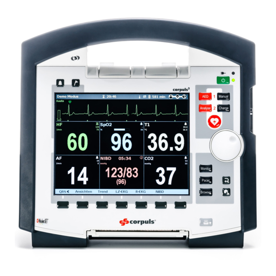
Short Manual
This short manual is meant to give an exploratory overview of
the essential functions of the corpuls
3
.
Reading this short manual is no substitute neither for the
necessity to carefully read through the user manual nor for the
instruction and training on the device by an authorised medical
products consultant.
Advertisement
Table of Contents

Related Manuals for GS corpuls3


Summary of Contents for GS corpuls3
- Page 1 Short Manual This short manual is meant to give an exploratory overview of the essential functions of the corpuls Reading this short manual is no substitute neither for the necessity to carefully read through the user manual nor for the instruction and training on the device by an authorised medical products consultant.
-
Page 2: Charging The Battery
Charging the Battery Charging compact device via charging bracket Inserting compact device into charging bracket Fit the recesses at the bottom of the defibrillator onto the pins of the charging bracket (item A). The device will be locked automatically and the modules will be charged. - Page 3 Switching On and Off Switching the Compact Device On and Off To switch on/off, press the On/Off key at the monitoring unit. The compact device is swit- ched off after a confirmation prompt. Switching On and Off in Modular Use To switch on the monitoring unit, the patient box and the defibrillator in modular use, press the On/Off key at the respective module.
- Page 4 Printer and Printing Note The easiest way to open the printer flap is to disconnect the mo- nitoring unit from the defibrillator and place it on a flat surface. 1. Pull the locking lever (item 1) of the printer flap slightly downwards to unlock (item A) the printer flap (item 2) and open it downwards...
- Page 5 Separating and Connecting Compact Monitor and Defibrillator Separating the Compact Monitor 1. Grasp the compact monitor by the carrying handle and pull both snap locks simultaneously forwards and upwards (item A) or push them rearwards and downwards (item B). 2. Tilt the monitoring unit for- wards (item C) and remove upwards (item D).
- Page 6 Separating and Connecting the Patient Box Separating the Patient Box 1. Grasp the monitoring unit by the carrying handle and press the snap lock of the patient box downwards (item A). 2. Tilt the patient box rear- wards (item B) and remove (item C).
- Page 7 Separating and Connecting Compact Monitor and Defibrillator SLIM Separating Defibrillator SLIM 1. Grasp the compact monitor by the carrying handle and pull both snap locks simultaneously forwards and upwards (item A) or push them rearwards and downwards (item B). 2. Tilt the monitoring unit for- wards (item C) and remove upwards (item D).
- Page 8 Radio Connection Patient Box In case of malfunctions of the radio connection, take the following measures: The distance between the modules is not greater than 10 meters. 1. The antenna of the radio unit is located at the top of the patient box (see symbol).
- Page 9 Manual Defibrillation/Cardioversion Defibrillation/Cardioversion with corPatch Therapy Electrodes Attach the corPatch therapy electrodes to the thorax of the patient as shown on the packa- ge and connect to the therapy master cable, if necessary. 1. Press the Manual key (item 1) for a quick boot-up in manual defibrillation mode.
- Page 10 Defibrillation in the AED Mode Defibrillation with corPatch Therapy Electrodes Attach the corPatch therapy electrodes to the thorax of the patient as shown on the packa- ge and connect to the therapy master cable, if necessary. 1. Press the AED key (item 1) for a quick boot-up in AED defibrillation mode.
- Page 11 corPatch CPR CPR Feedback If a corPatch CPR sensor is used, the rate and depth of a thorax compression can be measured. Speech- and text mes- sages like "Push harder" or "Good compressions" inform the user of the quality of the thorax compressions. "Fully release"...
-
Page 12: External Pacer
External Pacer Pacing 1. To call up the pacer func- tion, press the Pacer key (item 1). 2. Attach the corPatch therapy electrodes to the patient's thorax (anterior/posterior) and connect them to the therapy master cable, if necessary (see below, on the left). - Page 13 Diagnostic ECG Diagnostic ECG To monitor the heart rhythm and heart rate, place all 4 ECG electrodes of the 4-pole ECG monitoring cable on the patient: • Red ECG electrode: right arm (item 1) • Yellow ECG electrode: left arm (item 2) •...
- Page 14 Monitoring Vital Parameters If the curve fields or parameter fields of the connected measu- ring option are not displayed automatically, they have to be se- lected. Select via the main menu (jog dial "Signals" "Curves/ Parameters") or via the parameter or curve context menu. Parameter Context Menu and Curve Context Menu Select the required parameter/curve field with the jog dial and confirm by pressing the jog dial.
- Page 15 ECG Monitoring Positioning the ECG Monitoring cable Place all four ECG electrodes of the 4-pole ECG monitoring cable on the patient: • Red ECG electrode: under the right clavicle • Yellow ECG electrode: under the left clavicle • Green ECG electrode: in the area of the left inguinal fold, central to the axis of the leg •...
- Page 16 NIBP Measurement Attaching the Cuff Attach the deflated NIBP cuff firmly to the patient’s exposed upper arm at heart level. The NIBP cuff should not exert any pressure on the blood vessels. The lower edge of the NIBP cuff should be positioned approx. 2 cm above the crook of the arm.
- Page 17 Telemetry/Data Management Fax Transmission to a Fax Machine 1. Record a diagnostic ECG. 2. After the message "D-ECG measured" is displayed, press the softkey [Send]. The phonebook overview with pre-confi- gured destinations appears. 3. Select the required destination or "Manual destination" with the jog dial and press to confirm.
- Page 18 Alarm- and Event Management Alarm Design Alarms can have high (!!!), medium (!!) and low (!) priority. These priorities are signalled acoustically by different series of tones and visually by inverted colours of the parameter field, highlighting the status line in different colours and flashing of the alarm light in different colours and intervals.
- Page 19 Maintenance Daily Check 1. Check the accessories/consumables for completeness. 2. Perform a visual check of the device and the mechanical connections. 3. Switch on the compact device and check if the internal self- test results in any error messages. 4. Select manual defibrillation mode. Select an energy of 200 J with the jog dial or the softkeys.
- Page 20 For further information please contact: Your business card GS Elektromedizinische Geräte G. Stemple GmbH · Hauswiesenstraße 26 · 86916 Kaufering · Germany +49 8191 65722-0 · info@corpuls.com · www.corpuls.com ENG - Version 2.2 - P/N 04131.02...
Need help?
Do you have a question about the corpuls3 and is the answer not in the manual?
Questions and answers