Table of Contents
Advertisement
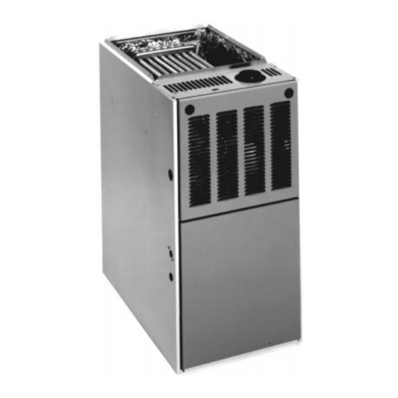
INSTALLATION INSTRUCTIONS
FOR UPFLOW (RGDG & RGDJ), UPFLOW/HORIZONTAL
(RGPH & RGPJ), HORIZONTAL ONLY (RGVH & RGVJ)
AND DOWNFLOW (RGLH & RGLJ) INDUCED DRAFT
GAS FURNACES
!
Recognize this symbol as an indication of Important Safety Information!
WARNING
!
If the information in these instructions is not followed exactly, a
fire or explosion may result, causing property damage, personal
injury or death.
WARNING
!
PROPOSITION 65: THIS FURNACE CONTAINS FIBERGLASS
INSULATION. RESPIRABLE PARTICLES OF FIBERGLASS ARE
KNOWN TO THE STATE OF CALIFORNIA TO CAUSE CANCER.
EXHAUST GAS FROM THIS FURNACE CONTAINS CHEMICALS,
INCLUDING CARBON MONOXIDE, KNOWN TO THE STATE OF
CALIFORNIA TO CAUSE BIRTH DEFECTS OR OTHER REPRO-
DUCTIVE HARM.
WARNING
!
THESE INSTRUCTIONS ARE
INTENDED AS AN AID TO
QUALIFIED SERVICE
PERSONNEL FOR PROPER
INSTALLATION, ADJUSTMENT
AND OPERATION OF THIS
UNIT. READ THESE
INSTRUCTIONS THOROUGHLY
BEFORE ATTEMPTING
INSTALLATION OR
OPERATION. FAILURE TO
FOLLOW THESE
INSTRUCTIONS MAY RESULT
IN IMPROPER INSTALLATION,
ADJUSTMENT, SERVICE OR
MAINTENANCE, POSSIBLY
RESULTING IN FIRE,
ELECTRICAL SHOCK, CARBON
MONOXIDE POISONING,
EXPLOSION, PROPERTY
DAMAGE, PERSONAL INJURY
OR DEATH.
Do Not Destroy this Manual.
Please read carefully and keep
in a safe place for future
reference by a serviceman.
FOR YOUR SAFETY
!
— Do not store or use gasoline or other
flammable vapors and liquids, or other
combustible materials in the vicinity of this
or any other appliance.
— WHAT TO DO IF YOU SMELL GAS
• Do not try to light any appliance.
• Do not touch any electrical switch; do not
use any phone in your building.
• Immediately call your gas supplier from a
neighbor's phone. Follow the gas
supplier's instructions.
• If you cannot reach your gas supplier,
call the fire department.
• Do not return to your home until
authorized by the gas supplier or fire
department.
— DO NOT RELY ON SMELL ALONE TO
DETECT LEAKS. DUE TO VARIOUS
FACTORS, YOU MAY NOT BE ABLE TO
SMELL FUEL GASES.
• U.L. recognized fuel gas and CO
detectors are recommended in all
applications, and their installation should
be in accordance with the manufacturer's
recommendations and/or local laws,
rules, regulations, or customs
— Improper installation, adjustment, alteration,
service or maintenance can cause injury,
property damage or death. Refer to this
manual. Installation and service must be
performed by a qualified installer, service
agency or the gas supplier.
92-23531-70-01
SUPERSEDES 92-23531-70-00
Advertisement
Table of Contents

Related Manuals for Rheem RGPH


Summary of Contents for Rheem RGPH
-
Page 1: Installation Instructions
INSTALLATION INSTRUCTIONS FOR UPFLOW (RGDG & RGDJ), UPFLOW/HORIZONTAL (RGPH & RGPJ), HORIZONTAL ONLY (RGVH & RGVJ) AND DOWNFLOW (RGLH & RGLJ) INDUCED DRAFT GAS FURNACES Recognize this symbol as an indication of Important Safety Information! WARNING If the information in these instructions is not followed exactly, a fire or explosion may result, causing property damage, personal injury or death. -
Page 2: Installation Check List
Before beginning any troubleshooting procedure, complete the following installation checklist. A furnace malfunction is sometimes caused by an improper installation. By completing this checklist, the problem may be found and corrected. Make copies of the checklist and complete one for every Low Profile Furnace service call for your records. INSTALLATION CHECKLIST (Refer to this manual for specifics.) GAS SUPPLY... - Page 3 CONTENTS Safety Precautions ....................1 Installation Check List ....................2 Location Requirements and Considerations ............4 Combustion and Ventilation Air................10 Vent Pipe Installation....................13 Gas Supply and Piping...................16 Electrical Wiring......................20 Accessories ......................21 Start-Up Procedures....................26 Air Flow........................29 Maintenance......................34 Troubleshooting......................36 Wiring Diagrams.....................43 Installation Instructions are updated on a regular basis. This is done as product changes occur or if new information becomes available.
-
Page 4: Location Requirements And Considerations
GENERAL INFORMATION The RGDG/RGDJ/RGLH/RGLJ and entitled “National Fuel Gas Code” edition. NFPA-90B – Warm Air Heating RGPH/RGPJ/RGVH/RGVJ series (NFPA 54) (in Canada, CAN/CGA and Air Conditioning Systems 1984. furnaces are design certified by B149.1 and .2 Installation Codes for These publications are available from:... - Page 5 ⁄ CLEARANCE TO COMBUSTIBLE MATERIAL (INCHES) BOTTOM UPFLOW AND UPFLOW/HORIZONTAL MODELS REDUCED CLEARANCE (IN.) Left Right Ship. Model Back Front Vent Side Side Wgts. ⁄ ⁄ ⁄ 04, 05 85 lbs. ⁄ ⁄ ⁄ 06, 07 105 lbs. ⁄ ⁄ ⁄...
- Page 6 CLEARANCE TO COMBUSTIBLE MATERIAL (INCHES) DOWNFLOW MODELS REDUCED CLEARANCE (IN.) Left Right Ship. BOTTOM Model Back Front Vent Side Side Wgts. ⁄ ⁄ ⁄ 04, 05 85 lbs. ⁄ ⁄ ⁄ ⁄ 06, 07 105 lbs. ⁄ ⁄ ⁄ ⁄ 10(A) 115 lbs.
- Page 7 CLEARANCE TO COMBUSTIBLE MATERIAL (INCHES) HORIZONTAL “ONLY” MODELS REDUCED CLEARANCE (IN.) Left Right Ship. Model Back Front Vent Side Side Wgts. ⁄ ⁄ ⁄ 04, 05 85 lbs. ⁄ TOP VIEW ⁄ ⁄ ⁄ 06, 07 105 lbs. 10(A) ⁄ ⁄...
-
Page 8: Site Selection
CLEARANCE – UPFLOW UNIT DESIGN REQUIRES KEPT CLEAR AND FREE OF ALL A SOLID METAL BASE PLATE (SEE COMBUSTIBLE MATERIALS ACCESSIBILITY TABLE ON PAGE 8 OR FURNACE INCLUDING GASOLINE AND OTHER The design of forced air furnaces with CLEARANCE LABEL FOR PART FLAMMABLE VAPORS AND NUMBER) MUST BE IN PLACE LIQUIDS. -
Page 9: Horizontal Units
GAPS, ETC., AROUND THE BASE AS 3. Connect the return duct or return air BASE IS SHIPPED FROM THE cabinet to the unit. Make the FACTORY AS AN ACCESSORY. TO PROVIDE A SEAL BETWEEN connection air tight to prevent THE SUPPORT AND THE BASE. 4. -
Page 10: Combustion And Ventilation Air
IMPORTANT: Air for combustion and FIGURE 6 ventilation must not come from a HORIZONTAL RETURN AIR DUCT corrosive atmosphere. Any failure due to corrosive elements in the atmosphere is excluded from warranty coverage. The following types of installation may require OUTDOOR AIR for combustion, due to chemical exposures: •... - Page 11 Combustion air must be free of acid FIGURE 8 forming chemicals; such as sulphur, AIR FROM ATTIC/CRAWL SPACE fluorine and chlorine. These elements are found in aerosol sprays, detergents, bleaches, cleaning solvents, air fresheners, paint and varnish removers, refrigerants and many other commercial and household products.
- Page 12 FIGURE 9 OUTSIDE AIR USING A HORIZONTAL INLET & OUTLET a. One square inch for each 3000 VERTICAL OUTDOOR AIR HORIZONTAL OUTDOOR AIR BTUH of the total input rating of all OPENING DIMENSIONS OPENING DIMENSIONS equipment located in the enclosure, BTUH Free Area Round...
-
Page 13: Figure
VENTING FIGURE 10 ATTACHING TO DRAFT INDUCER COLLAR GENERAL INFORMATION The furnace must be vented in accordance with these instructions, National Fuel Gas Code, ANSI Z223.1 and/or the Natural Gas Installation Code, CAN/CGA-B149.1 & .2 and requirements or codes of the local utility or other authority having jurisdiction. -
Page 14: Power Vent Systems
SPECIAL VENT SYSTEMS (SVS) depending on application. See ANSI Z21.47-1993/CAN/CGA-2.3-M93 or latest connectors that are B-1 material. IMPORTANT: IT IS RHEEM’S edition tables. These shall be assembled in POSITION NOW THAT NEW accordance with the manufacturer’s... - Page 15 FIGURE 12 DEDICATED VENTING THROUGH CHIMNEY WITH “B-1” VENT EXISTING VENT SYSTEMS 3. Insofar as is practical, close all 6. After it has been determined that each appliance that remains building doors, windows and all IMPORTANT RETROFIT connected to the common venting doors between the space where the VENTING INSTRUCTIONS system properly vents (when tested...
-
Page 16: Gas Supply And Piping
GAS SUPPLY AND PIPING GAS SUPPLY FIGURE 13 GAS PIPING INSTALLATION WARNING UPFLOW & DOWNFLOW THIS FURNACE IS EQUIPPED AT THE FACTORY FOR USE ON NATURAL GAS ONLY. CONVER- SION TO LP GAS REQUIRES A SPECIAL KIT SUPPLIED BY THE DISTRIBUTOR OR MANU- FACTURER. -
Page 17: Gas Pressure
GAS PRESSURE FIGURE 15 LP KIT CONTENTS Natural gas supply pressure should be 5" to 7 w.c. LP gas supply pressure should be 11 to 14 w.c. This pressure must be maintained with all other gas-fired appliances in operation. Never exceed a maximum gas supply pressure of 14 w.c. - Page 18 LP CONVERSION ORIFICE SIZING CHART RATING PLATE ELEVATION The valve can be converted to use INPUT liquefied petroleum (LP) gas by BTU/HR 0 TO 7,999 FT. 8,000 FT. AND ABOVE replacing the pressure regulator spring HEATING VALUE @ 1,000 BTU/FT , SPECIFIC GRAVITY 0.62 with the conversion kit spring.
-
Page 19: Setting Gas Pressure
SETTING GAS PRESSURE The maximum gas supply pressure 2. Connect a U-Tube manometer to If the supply gas line pressure is above to the furnace should be 7 w.c. the pressure tap. See Figure 15. these ranges, install an in-line gas natural gas, or 14 w.c. -
Page 20: Electrical Wiring
ELECTRICAL WIRING FIGURE 17 ISOLATION RELAY WARNING TURN OFF ELECTRIC POWER AT THE FUSE BOX OR SERVICE PANEL BEFORE MAKING ANY ELECTRICAL CONNECTIONS. ALSO, THE GROUND CONNECTION MUST BE COMPLETED BEFORE MAKING LINE VOLTAGE CONNECTIONS. FAILURE TO DO SO CAN RESULT IN ELECTRICAL SHOCK, SEVERE PERSONAL INJURY OR DEATH. -
Page 21: Accessories
d. Connect wire from “RCV” FIGURE 18 terminal of board “ONE” to LINE VOLTAGE CONNECTIONS “XMIT” terminal of board HONEYWELL S9201E2001, UTEC 1012-920 AND WHITE RODGERS 50A62- “TWO.” 101 CONTROL BOARD e. Connect wire between the grounds. f. Connect wire between the two “W”... - Page 22 FIGURE 19 HONEYWELL NO. S9201E2001 CONTROL BOARD TWINNING CONNECTION SINGLE STAGE OPERATION I400...
- Page 23 FIGURE 20 HONEYWELL NO. S9201E2001 CONTROL BOARD TWINNING CONNECTION TWO STAGE OPERATION I400...
- Page 24 FIGURE 21 UTEC NO. 1012-920 OR WHITE RODGERS 50A62-101 CONTROL BOARD TWINNING CONNECTION SINGLE STAGE OPERATION I398...
- Page 25 FIGURE 22 UTEC NO. 1012-920 OR WHITE RODGERS 50A62-101 CONTROL BOARD TWINNING CONNECTION TWO STAGE OPERATION I399...
-
Page 26: Start-Up Procedures
START-UP PROCEDURE WHITE RODGERS 50A62-101 WITH HOT SURFACE IGNITION 3. 30 seconds after the pressure switch(es) close, the hot surface HOT SURFACE IGNITION LIGHTING INSTRUCTIONS igniter heats for 30 seconds to full 1. Each time the thermostat contacts temperature. The induced draft blower close, the induced draft blower This appliance is equipped with a hot operates for the complete heating... - Page 27 SETTING BLOWER TIMINGS GAS FURNACE (DIRECT motor leads to “M1” or “M2.” Check motor lead color for speed designation. DRIVE) INSTRUCTIONS FOR The Honeywell and UTEC control Heating speeds should not be reduced CHANGING BLOWER SPEED boards have four quick connect where it could cause the furnace air terminals for connecting the motor temperature to rise to exceed the...
- Page 28 Furnaces for use on LP gas, the LP ORIFICE SIZING CHART gas supply pressure must be set RATING PLATE ELEVATION between 11.0 and 14.0 W.C. by INPUT means of the tank or branch supply BTU/HR 0 TO 7,999 FT. 8,000 FT. AND ABOVE regulators.
-
Page 29: Air Flow
AIR FLOW FIGURE 26 TEMPERATURE RISE MEASUREMENT The importance of proper air flow over the heat exchanger cannot be over emphasized. One of the most common causes of heat exchanger failure is overheating due to low air flow. An air flow table is located inside the blower door and on the following pages. - Page 30 BLOWER PERFORMANCE DATA – RGDG & RGPH UPFLOW/HORIZONTAL MODELS BLOWER PERFORMANCE DATA – RGLH DOWNFLOW MODELS...
- Page 31 BLOWER PERFORMANCE DATA – RGVH HORIZONTAL MODELS BLOWER PERFORMANCE DATA – RGDJ & RGPJ UPFLOW/HORIZONTAL MODELS...
- Page 32 BLOWER PERFORMANCE DATA – RGLJ DOWNFLOW MODELS ONLY BLOWER PERFORMANCE DATA – RGVJ HORIZONTAL MODELS...
-
Page 33: Safety Features
LUBRICATION FIGURE 28 The blower motor and induced draft DOWNFLOW BLOWER REMOVAL motor are prelubricated by the manufacturer and do not require further attention. The motor must be cleaned periodically by a qualified installer, service agency, or the gas supplier to prevent the possibility of overheating due to an accumulation of dust and dirt on the windings or on the motor... -
Page 34: Maintenance
MAINTENANCE FIGURE 29 RESIZING FILTERS & FRAME WARNING DISCONNECT MAIN ELECTRICAL POWER TO THE UNIT BEFORE ATTEMPTING ANY MAINTENANCE. FAILURE TO DO SO CAN CAUSE ELECTRICAL SHOCK RESULTING IN SEVERE PERSONAL INJURY OR DEATH. FILTERS NOTE: RGDJ, RGPJ, RGVJ, RGLJ and RGVH models are not factory equipped with filters. - Page 35 FIGURE 31 FILTER RETAINING RODS (SIDE RETURN) FIGURE 32 DOWNFLOW FILTER INSTALLATION...
-
Page 36: Troubleshooting
IMPORTANT: Do not operate the 12. Flush each heat exchanger tube WARNING system for extended periods without with water from a hose and blow HOLES IN THE VENT PIPE OR HEAT filters. A portion of the dust entrained out with air to remove excessive EXCHANGER CAN CAUSE TOXIC in the air may temporarily lodge in the moisture. - Page 37 FIGURE 33 INTEGRATED FURNACE CONTROL (IFC) TROUBLESHOOTING GUIDE FOR UTEC 1012-920 & HONEYWELL S9201E2001 (115 VAC IGNITER) WARNING DISCONNECT POWER BEFORE HAZARDOUS VOLTAGE SERVICING. LINE VOLTAGE SERVICE MUST BE BY A TRAINED, CONNECTIONS QUALIFIED SERVICE TECHNICIAN. START 1. SET FAN SWITCH TO AUTO 2.
- Page 38 NOTE: IF (IFC) GOES INTO LOCKOUT WAIT 30 SECONDS THEN MAIN BURNER RESET SYSTEM REMAINS POWERED AND LIT • CHECK POLARITY OF 115VAC SUPPLY • CHECK CONTINUITY OF GROUND WIRE • CHECK INSULATION OF IGNITER LEADS • CHECK FLAME SENSE CURRENT (YELLOW LED) LED IS ON IF FLAME CURRENT IS GOOD.
- Page 39 FIGURE 34 INTEGRATED FURNACE CONTROL (IFC) WHITE RODGERS 50A62-101 (SILICON-NITRIDE IGNITER) WHITE-RODGERS 50A62-101 START INTEGRATED FURNACE CONTROL (IFC) 1. SET FAN SWITCH TO AUTO TROUBLESHOOTING GUIDE 2. SET THERMOSTAT TO CALL (SILICON-NITRIDE IGNITER) FOR HEAT INDUCED DRAFT BLOWER • REMOVE (IFC) COVER, CHECK LIGHTS MOTOR STARTS •...
- Page 40 SYSTEM WILL ATTEMPT TO LIGHT 4 TIMES. VOLTAGE IS PRESENT AT THE VALVE FOR ONLY 8 SECONDS DURING EACH TRIAL FOR IGNITION (SYSTEM WILL GO INTO A 1-HOUR LOCKOUT AFTER 4 TRIES), THE SEQUENCE WILL MAIN BURNER REPEAT AFTER A ONE HOUR DELAY. IT WILL CONTINUE UNTIL IGNITION IS LIGHTS SUCCESSFUL OR THE CALL FOR HEAT IS TERMINATED.
- Page 41 FIGURE 35 INTEGRATED FURNACE CONTROL (IFC) UTEC 1012-925 (115 VAC IGNITER) WARNING HAZARDOUS VOLTAGE DISCONNECT POWER BEFORE LINE VOLTAGE SERVICING. CONNECTIONS SERVICE MUST BE BY A TRAINED, QUALIFIED SERVICE TECHNICIAN. NOTE: STATIC DISCHARGE CAN DAMAGE INTEGRATED FURNACE CONTROL (IFC) • “OK” LED BLINKS TO INDICATE EXTERNAL FAULTS: (1) BLINK FOLLOWED BY A 2 SEC.
- Page 42 SYSTEM WILL ATTEMPT TO LIGHT 4 TIMES. VOLTAGE IS PRESENT AT THE VALVE FOR ONLY 8 SECONDS DURING EACH TRIAL FOR IGNITION (SYSTEM WILL GO INTO A 1-HOUR LOCKOUT AFTER 4 TRIES), THE BLOWER AND INDUCED DRAFT BLOWER WILL RUN 100 SEC. IF THE SECOND IGNITION TRIAL FAILS TO SENSE FLAME •...
- Page 43 FIGURE 36 FOR MODELS WITH UTEC 1012-920 OR HONEYWELL S9201E2001 INTEGRATED FURNACE CONTROL...
- Page 44 FIGURE 37 FOR MODELS WITH WHITE RODGERS 50A62-101 INTEGRATED FURNACE CONTROL...
- Page 45 FIGURE 38 FOR MODELS WITH UTEC 1012-925 INTEGRATED FURNACE CONTROL...
- Page 48 Rheem Manufacturing Company Air Conditioning Division CM 398 Fort Smith, Arkansas...