
Related Manuals for TEAMWELDER TIG 180 AC/DC puls


Summary of Contents for TEAMWELDER TIG 180 AC/DC puls
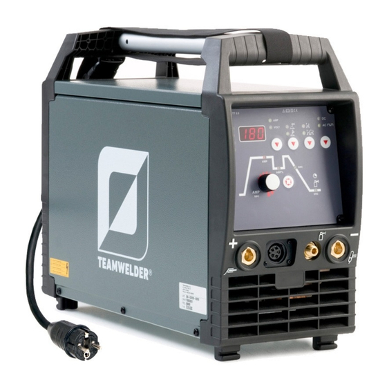
- Page 1 Operating instructions Welding machine TIG 180 AC/DC puls 299-020200-TWD01 14.07.2017...
-
Page 2: General Instructions
+49 2623 9276400. A list of authorised sales partners can be found at www.teamwelder.com. Liability relating to the operation of this equipment is restricted solely to the function of the equipment. - Page 3 Contents Notes on the use of these operating instructions Contents 1 Contents ..............................3 2 For your safety ............................5 Notes on the use of these operating instructions ................5 Explanation of icons ........................6 Part of the complete documentation ....................7 Safety instructions ..........................
- Page 4 Error messages (power source) ....................51 Resetting welding parameters to the factory settings ..............52 Display machine control software version ..................52 8 Technical data............................53 TIG 180 AC/DC puls ........................53 9 Accessories ............................54 Internet ............................54 10 Appendix A ............................55 10.1 Parameter overview –...
-
Page 5: For Your Safety
For your safety Notes on the use of these operating instructions For your safety Notes on the use of these operating instructions DANGER Working or operating procedures which must be closely observed to prevent imminent serious and even fatal injuries. •... -
Page 6: Explanation Of Icons
For your safety Explanation of icons Explanation of icons Symbol Description Symbol Description Indicates technical aspects which the Activate and release/tap/tip user must observe. Switch off machine Release Switch on machine Press and keep pressed Switch Wrong Turn Numerical value – adjustable Correct Menu entry Signal light lights up in green... -
Page 7: Part Of The Complete Documentation
For your safety Part of the complete documentation Part of the complete documentation These operating instructions are part of the complete documentation and valid only in combination with all other parts of these instructions! Read and observe the operating instructions for all system components, especially the safety instructions! The illustration shows a general example of a welding system. - Page 8 For your safety Safety instructions WARNING Risk of injury from electrical voltage! Voltages can cause potentially fatal electric shocks and burns on contact. Even low voltages can cause a shock and lead to accidents. • Never touch live components such as welding current sockets or stick, tungsten or wire electrodes! •...
- Page 9 For your safety Safety instructions WARNING Fire hazard! Due to the high temperatures, sparks, glowing parts and hot slag that occur during welding, there is a risk of flames. • Be watchful of potential sources of fire in the working area! •...
- Page 10 For your safety Safety instructions CAUTION According to IEC 60974-10, welding machines are divided into two classes of electromagnetic compatibility (the EMC class can be found in the Technical data) > see 8 chapter: Class A machines are not intended for use in residential areas where the power supply comes from the low-voltage public mains network.
-
Page 11: Transport And Installation
For your safety Transport and installation The manufacturer's warranty becomes void if non-genuine parts are used! • Only use system components and options (power sources, welding torches, electrode holders, remote controls, spare parts and replacement parts, etc.) from our range of products! •... - Page 12 For your safety Transport and installation Protective dust caps protect the connection sockets and therefore the machine against dirt and damage. • The protective dust cap must be fitted if there is no accessory component being operated on that connection. •...
-
Page 13: Intended Use
In case of unauthorised changes, improper repairs, non-compliance with specified deadlines for "Arc Welding Equipment – Inspection and Testing during Operation", and/or prohibited modifications which have not been explicitly authorised by TEAMWELDER, this declaration shall be voided. An original document of the specific declaration of conformity is included with every product. -
Page 14: Machine Description – Quick Overview
Machine description – quick overview Front view Machine description – quick overview Front view Figure 4-1 Item Symbol Description Carrying handle Machine control > see 4.3 chapter Connection socket, welding torch control cable > see 5.3.1.1 chapter Connection socket, "+" welding current •... -
Page 15: Rear View
Machine description – quick overview Rear view Rear view Figure 4-2 Item Symbol Description 8-pole connection socket Cooling unit control lead Ignition type changeover switch > see 5.3.6 chapter = ------ Liftarc (contact ignition) = ------ HF ignition Main switch, machine on/off Cooling air outlet Machine feet Mains connection cable >... -
Page 16: Machine Control – Operating Elements
Machine description – quick overview Machine control – Operating elements Machine control – Operating elements The setting ranges for the parameter values are summarised in the Parameter overview section > see 10.1 chapter. Figure 4-3 Item Symbol Description Welding data display (3-digit) Displays the welding parameters and the corresponding values >... - Page 17 Machine description – quick overview Machine control – Operating elements Item Symbol Description Signal light, gas post-flow time Welding current polarity push-button -------- DC welding with negative polarity at the torch (or electrode holder) with respect to the workpiece. --- Alternating current welding/alternating current forms > see 5.3.4 chapter Pulsed welding push-button TIG ------- pulsed welding >...
-
Page 18: Design And Function
Design and function Transport and installation Design and function WARNING Risk of injury from electric shock! Contact with live parts, e.g. welding current sockets, is potentially fatal! • Follow safety instructions on the opening pages of the operating instructions. • Commissioning may only be carried out by persons who have the relevant expertise of working with arc welding machines! •... -
Page 19: Workpiece Lead, General
Design and function Transport and installation 5.1.3 Workpiece lead, general CAUTION Risk of burning due to incorrect welding current connection! If the welding current plugs (machine connections) are not locked or if the workpiece connection is contaminated (paint, corrosion), these connections and leads can heat up and cause burns when touched! •... -
Page 20: Welding Torch Cooling System
Design and function Transport and installation 5.1.5 Welding torch cooling system 5.1.5.1 Welding torch cooling unit connection Figure 5-2 Item Symbol Description 8-pole connection socket Cooling unit control lead 5-pole connection socket Cooling unit voltage supply Cooling module • Insert and lock the 8-pole control lead plug on the cooling unit into the 8-pole connection socket on the welding machine. -
Page 21: Notes On The Installation Of Welding Current Leads
Design and function Transport and installation 5.1.6 Notes on the installation of welding current leads Incorrectly installed welding current leads can cause faults in the arc (flickering). Lay the workpiece lead and hose package of power sources without HF igniter (MIG/MAG) for as long and as close as possible in parallel. -
Page 22: Stray Welding Currents
Design and function Transport and installation Figure 5-5 5.1.6.1 Stray welding currents WARNING Risk of injury due to stray welding currents! Stray welding currents can destroy protective earth conductors, damage machines and electronic devices and cause overheating of components, leading to fire. •... -
Page 23: Mains Connection
Design and function Welding data display 5.1.7 Mains connection DANGER Hazards caused by improper mains connection! An improper mains connection can cause injuries or damage property! • Only operate machine using a socket that has correctly fitted protective earth. • The mains voltage indicated on the rating plate must match the supply voltage. -
Page 24: Tig Welding
Design and function TIG welding TIG welding 5.3.1 Welding torch and workpiece line connection Prepare welding torch according to the welding task in hand (see operating instructions for the torch). Figure 5-8 Item Symbol Description Welding torch Welding torch hose package Connection socket, "-"... -
Page 25: Connection Assignment, Welding Torch Control Cable
Design and function TIG welding 5.3.1.1 Connection assignment, welding torch control cable Figure 5-9 5.3.2 Shielding gas supply (shielding gas cylinder for welding machine) WARNING Risk of injury due to improper handling of shielding gas cylinders! Improper handling and insufficient securing of shielding gas cylinders can cause serious injuries! •... -
Page 26: Welding Task Selection
Design and function TIG welding • Before connecting the pressure regulator to the gas cylinder, open the cylinder valve briefly to blow out any dirt. • Tighten the pressure regulator screw connection on the gas bottle valve to be gas-tight. •... -
Page 27: Ac Welding
Design and function TIG welding 5.3.4 AC welding 5.3.4.1 AC balance (optimise cleaning effect and penetration characteristics) To weld aluminium and aluminium alloys, AC welding is used in combination with a continuous change in polarity of the tungsten electrode. The process encompasses two phases (half-waves): a positive and a negative one. -
Page 28: Arc Ignition
Design and function TIG welding 5.3.6 Arc ignition To change the ignition type, use parameter to switch between HF start ( ) and lift arc ( ) in the Expert menu > see 5.3.10 chapter. 5.3.6.1 HF ignition Figure 5-13 The arc is started without contact from high-voltage ignition pulses. -
Page 29: Operating Modes (Functional Sequences)
Design and function TIG welding 5.3.7 Operating modes (functional sequences) Using the welding parameter push-button and welding parameter setting rotary knob the sequence parameters are set. Figure 5-15 Item Symbol Description Select welding parameters button This button is used to select the welding parameters depending on the welding process and operating mode used. -
Page 30: Non-Latched Mode
Design and function TIG welding 5.3.7.2 Non-latched mode Figure 5-16 1st cycle: • Press and hold torch trigger 1. • The gas pre-flow time elapses. • HF ignition pulses jump from the electrode to the workpiece, the arc ignites. • The welding current flows and immediately assumes the value set for the ignition current I start •... -
Page 31: Latched Mode
Design and function TIG welding 5.3.7.3 Latched mode Figure 5-17 Step 1 • Press torch trigger 1, the gas pre-flow time elapses. • HF ignition pulses jump from the electrode to the workpiece, the arc ignites. • Welding current flows and immediately assumes the ignition current value set (search arc at minimum setting). -
Page 32: Average Value Pulsing
Design and function TIG welding 5.3.7.4 Average value pulsing Once the function is activated, the red signal lights for the main current AMP and secondary current AMP% light up at the same time. Average value pulse welding means that the system switches between two currents periodically, an average current value (AMP), a pulse current (Ipuls), a balance ( ) and a frequency ( ) having been... -
Page 33: Welding Torch (Operating Variants)
Design and function TIG welding 5.3.9 Welding torch (operating variants) Different torch versions can be used with this machine. Functions on the operating elements, such as torch triggers (BRT), rockers or potentiometers, can be modified individually via torch modes. Explanation of symbols for operating elements: Symbol Description Press torch trigger... -
Page 34: Current Jump
Design and function TIG welding 5.3.9.4 Current jump This function is only available when using up/down torches in modes 4 and 14! By tapping the corresponding torch trigger the welding current can be determined in an adjustable jump range. Each tap will cause the welding current to jump up or down by the defined value. EXIT Figure 5-20 Display... -
Page 35: Standard Tig Torch (5-Pole)
Design and function TIG welding 5.3.9.5 Standard TIG torch (5-pole) Standard torch with one torch trigger Figure Operating Explanation of symbols elements BRT1 = torch trigger 1 (welding current on/off; secondary current via tapping function) Functions Mode Operating elements Welding current on/off (ex works) Secondary current (latched operation) Standard torch with two torch triggers... - Page 36 Design and function TIG welding Standard torch with one rocker (rocker, two torch triggers) Figure Operating Explanation of symbols elements BRT 1 = torch trigger 1 BRT 2 = torch trigger 2 Functions Mode Operating elements Welding current on/off Secondary current (ex works) Secondary current (tapping function) )/(latched operating mode)
-
Page 37: Expert Menu (Tig)
Design and function TIG welding 5.3.10 Expert menu (TIG) The Expert menu has adjustable parameters stored that don’t require regular setting. The number of parameters shown may be limited, e.g. if a function is deactivated. The setting ranges for the parameter values are summarised in the Parameter overview section >... -
Page 38: Mma Welding
Design and function MMA welding MMA welding 5.4.1 Connecting the electrode holder and workpiece lead CAUTION Risk of crushing and burns! When changing stick electrodes there is a risk of crushing and burns! • Wear appropriate and dry protective gloves. •... -
Page 39: Welding Task Selection
Design and function MMA welding 5.4.2 Welding task selection It is only possible to change the basic parameters when no welding current is flowing and any possible access control is disabled > see 5.7 chapter. The following welding task selection is an example of use. In general, the selection process always has the same sequence. -
Page 40: Average Value Pulse Welding
Design and function MMA welding 5.4.5 Average value pulse welding Average value pulse welding means that two currents are switched periodically, a current average value (AMP), a pulse current (Ipuls), a balance ( ) and a frequency ( ) having been defined first. The predefined ampere current average value is decisive, the pulse current (Ipuls) is defined by the parameter as a percentage of the current average value (AMP). -
Page 41: Remote Control
Design and function Remote control Display Setting/selection Hotstart time Pulse balance Pulse frequency Pulse current > see 5.4.5 chapter Remote control The remote controls are operated on the 19-pole remote control connection socket (analogue). 5.5.1 TW-RT1 19POL Functions • Infinitely adjustable welding current (0% to 100%) depending on the preselected main current on the welding machine. -
Page 42: Access Control
Design and function Access control Item Signal shape Designation Output Connection for cable screen (PE) Output Current flowing signal I>0, galvanically isolated (max. +- 15V/100mA) Output Reference voltage for potentiometer 10V (max. 10mA) Input Control voltage specification for main current, 0–10V (0V = I /10V = Input Control voltage specification for secondary current, 0–10V (0V =... -
Page 43: Machine Configuration Menu
Design and function Machine configuration menu Machine configuration menu Basic machine settings are defined in the machine configuration menu. 5.9.1 Selecting, changing and saving parameters ENTER NAVIGATION EXIT Figure 5-29 299-020200-TWD01 14.07.2017... - Page 44 Design and function Machine configuration menu Display Setting/selection Lock JOB menu Protect welding parameters from unauthorised access. Machine code Querying the three-digit machine code (000 to 999), user input Error Error message after entering an incorrect machine code Switch on Switching on machine function Switch off Switching off machine function...
- Page 45 Design and function Machine configuration menu Machine fan test Machine fan is switched on Software version of the machine control Version display (example 034 = version 34) Access control – access code Setting: 000 to 999 (000 ex works) Error Error message after entering an incorrect machine code New machine code •...
-
Page 46: Maintenance, Care And Disposal
Maintenance, care and disposal General Maintenance, care and disposal General DANGER Risk of injury due to electrical voltage after switching off! Working on an open machine can lead to fatal injuries! Capacitors are loaded with electrical voltage during operation. Voltage remains present for up to four minutes after the mains plug is removed. -
Page 47: Maintenance Work, Intervals
Maintenance, care and disposal Maintenance work, intervals Maintenance work, intervals Repair and maintenance work may only be performed by qualified authorised personnel; otherwise the right to claim under warranty is void. In all service matters, always consult the dealer who supplied the machine. -
Page 48: Annual Test (Inspection And Testing During Operation)
07416/08-ECZ, and EKO-KOM with the Reg. No. F00034148. Meeting the requirements of RoHS We, TEAMWELDER Germany GmbH, hereby confirm that all products which we supply to you that are subject to the RoHS Directive comply with the requirements of the RoHS (Directive 2011/65/EU). -
Page 49: Rectifying Faults
Rectifying faults Checklist for rectifying faults Rectifying faults All products are subject to rigorous production checks and final checks. If, despite this, something fails to work at any time, please check the product using the following flowchart. If none of the fault rectification procedures described leads to the correct functioning of the product, please inform your authorised dealer. - Page 50 Rectifying faults Error messages (power source) Unstable arc Material inclusions in the tungsten electrode due to contact with filler material or workpiece Regrind or replace the tungsten electrode Incompatible parameter settings Check settings and correct if necessary Pore formation ...
-
Page 51: Error Messages (Power Source)
Rectifying faults Error messages (power source) Error messages (power source) A welding machine error is indicated by an error code being displayed (see table) on the display on the machine control. In the event of a machine error, the power unit is shut down. The display of possible error numbers depends on the machine version (interfaces/functions). -
Page 52: Resetting Welding Parameters To The Factory Settings
Rectifying faults Resetting welding parameters to the factory settings Resetting welding parameters to the factory settings All customised welding parameters that are stored will be replaced by the factory settings. RESET Figure 7-1 Display Setting/selection Input confirmation User entries are applied, release button(s). Display machine control software version The query of the software versions only serves to inform the authorised service staff. -
Page 53: Technical Data
Technical data TIG 180 AC/DC puls Technical data Performance specifications and guarantee only in connection with original spare and replacement parts! TIG 180 AC/DC puls Setting range for welding current 3 A–180 A 3 A–140 A Setting range for welding voltage 10.1 V–17.2 V... -
Page 54: Accessories
Accessories Internet Accessories Internet For the accessories available for your product go to www.teamwelder.com. Figure 9-1 299-020200-TWD01 14.07.2017... -
Page 55: Appendix A
Appendix A Parameter overview – setting ranges Appendix A Parameter overview – setting ranges 10.1 Parameters/function Setting range Gas pre-flow time Ignition current Up-slope time 20,0 Secondary current AMP% End current Diameter of tungsten electrode/ignition optimisation AC balance AC frequency Pulse balance Pulse frequency Pulse current...
Need help?
Do you have a question about the TIG 180 AC/DC puls and is the answer not in the manual?
Questions and answers