
Related Manuals for Tettex MIDAS 2881

Summary of Contents for Tettex MIDAS 2881
-
Page 1: Operating Instructions
Operating Instructions HAEFELY TEST AG MIDAS 2881 Mobile Insulation Diagnosis & Analysing System Version 2.0 (LAN version only) 4843930... - Page 2 Art.Nr. 4843930 Operating Instructions MIDAS 2881 Date Version Responsible Changes/Reasons 04.16 2881 LAN Version, replace the firewire model...
- Page 3 All repairs and upgrades that require the unit to be opened must be referred to HAEFELY TEST AG or one of their nominated agents. This Manual is only for Midas 2881 with Ethernet (LAN) connection to computer, for those equipped with FireWire connection type refers to the corresponding manual.
- Page 4 Manual Conventions In the manual, the following conventions are used: Indicates a matter of note. If it refers to a sequence of operations, failure to follow the instructions could result in errors in measurement. Indicates hazards. There is a risk of equipment damage or personal injury or death. Carefully read and follow the instructions.
- Page 5 Foreword Welcome as a new user of the Insulation Diagnosis System MIDAS 2881. Thank you for placing your confidence in our product. With the purchase of this measuring instrument you have opted for all the advantages that have built a world-wide reputation for a Tettex Instrument: Robustness, performance and quality assured. As a result this instrument provides a solution which achieves the optimal combination of traditional know- how and leading edge technology.
- Page 7 Contents 1 Introduction 1 Receiving Instructions ..................1 General ......................1 Hardware ......................1 Software ......................2 Scope of Supply ....................2 Optional Accessories ..................3 2 Technical Data 4 ...
- Page 8 Safety Ground (Earthing) ................29 Emergency Stop ................... 30 Warning Lamp Bar ..................30 7 Software 31 General ......................31 7.1.1 Start-up ..................31 7.1.2 Main Window ................32 ...
- Page 9 9 Instrument Storage 105 10 Packing and Transport 106 11 Recycling 107 12 Trouble Shooting 108 12.1 Software Updates ..................108 13 Conformity 109 Appendix 110 14 Applications Guide 111 14.1 Bushings ..................... 111 14.1.1 Spare Bushings ................
-
Page 11: Introduction
1 Introduction Receiving Instructions When taking delivery, any possible transport damage should be noted. A written record should be made of any such damage. A suitable remark should be recorded on the delivery documents. A claim for damage must be reported immediately to the transport company and to the Customer Support Department of HAEFELY TEST AG or the local agent. -
Page 12: Software
MIDAS standard type supplies 12kV, * MIDAS G type supplies 15kV Control Computer Fully installed Laptop in shell case (MIDAS 2881) Cables in rugged trolley including Shielded measuring cable, unipolar, LEMO plug, 20m, with clamp, indicator blue Shielded measuring cable, unipolar, LEMO plug, 20m, with clamp, indicator white... -
Page 13: Optional Accessories
Optional Accessories This chapter describes the accessories that can be used in conjunction with the MIDAS. Contact us directly if you have a special application, as the following list is only a part of the broad range of accessories available. Type / Series Description 288x TEMP... -
Page 14: Technical Data
30 min. ON / 1h 5 min. ON / 1h 1 min. ON / 1h 1 Can be expanded with optional Resonating Inductor 2 Can be reduced with additional filters on coupling capacitor Measuring Unit (MIDAS 2881 & MIDAS2881G) Range Resolution Accuracy Test Voltage <... - Page 15 Mechanical Weight & Dimensions Instrument 58 kg (128 lbs) 34 x 47 x 104 cm (13.5” x 18.5” x 41”) Trolley 11 kg (25 lbs) 33 x 68 x 112 cm (13” x 26.8” x 44”) General Control unit Lap top Computer Windows 7 based. Measuring unit With Internal and external Power supply and nominal capacitor Interfaces...
-
Page 16: Safety
Local and state safety procedures should also be consulted. Company and government regulations take precedence over Tettex recommendations. -
Page 17: Safety Features
Non-test related persons who are working in proximity to the area where testing is performed must be informed. Consistent visual and verbal signals should be agreed and followed. Perform only one job at a time on any equipment. The situation in which two crews are doing different tasks with the same equipment at the same time is an open invitation for confusion, trouble, and danger to the personnel. -
Page 18: Summary
It is strongly recommended that the test crew make a visual check to ensure that the equipment terminals are isolated from the power system. If there is real possibility that the device under test fails precautions such as barriers or entrance restrictions must be taken against harm in the event of violent failure. -
Page 19: Theory
4 Theory Why is Insulation Tested? All transformers, high voltage switchgear, motors and electrical equipment accessories have a high voltage lifespan. From the first day of use the equipment is subject to thermal and mechanical stresses, foreign particle ingress and variations in temperature and humidity. All of these influences raise the working temperature of the equipment when switched on. -
Page 20: What Is Dissipation Factor Tan
What is Dissipation Factor tan ? To specify the insulation loss factor, the test object must be considered in the test arrangement as a capacitor. Consider all test objects e.g. transformers, bushings, busbars, generators, motors, high voltage switchgear etc. are constructed from metal and insulation, and therefore possess associated capacitive properties. -
Page 21: The Difference Between Power Factor And Dissipation Factor
Because P = Q • tan , the losses which are proportional to tan , will usually be given as a value of tan to express the quality of an insulation material. Therefore the angle is described as loss angle and tan ... -
Page 22: Test Instruments
Test Instruments There are three basic kinds of capacitance, tan and Power Factor test instruments in use. Although the high accuracy Schering Bridge must be balanced manually and the balance observed on a null indicator, it has been widely sold and used for decades up until this day. The capacitance and dissipation factor can be calculated by reading the position of the balance elements. - Page 23 An increase of dissipation factor above a typical value may indicate conditions such as those showed above: If the dissipation factor varies significantly with voltage down to some voltage below which it is substantially constant, then ionization is indicated. If this extinction voltage is below the operating level, then ionization ma progress in operation with consequent deterioration.
- Page 24 Rubber 4.0% Silicone liquid 0.001% Varnished cambric, dry 1.0% Water 100% 1.0% @ 0°C Note: Tests for moisture should not be made at freezing temperatures because of the 100 to 1 ratio difference dissipation factor between water and ice. Influence of Temperature Most insulation measurements have to be interpreted based on the temperature of the specimen.
-
Page 25: Electrostatic Interference
Surface leakage errors can be minimized if dissipation factor measurements are made under condition where the weather is clear and sunny and where the relative humidity does not exceed 80%. In general, best results are obtained if measurements are made during late morning through mid afternoon. -
Page 26: Supplementary Test Methods
Supplementary Test Methods As of today there exists no other test method that can replace the currently used C tan test. Nevertheless, several measurement methods exist which compliment dissipation factor measurement and assist in localization of defects in the test object. Partial Discharge Measurement is unprotected against external electromagnetic disturbances and on-site measurement presents quite a lot of problems. -
Page 27: Parallel & Series Equivalent Circuits
*** Test current higher than 15A can’t be measured with this test system. External current dividers (current comparators) would affect functionality and/or accuracy of the midas288X. For range extension please contact TETTEX customer support. Example: =80nF (tan < 0.01), f=50Hz, internal AC source used, built-in C... -
Page 28: Functional Description
5 Functional Description System Overview To be able to execute correct and reproducible measurements it is essential to understand how the MIDAS measuring system works. The MIDAS measuring system is based on the double vector-meter method which relies upon the measurement of the current I through the known reference capacitor C and the measurement of the... -
Page 29: V-Potential Point And Guarding
Current trough Device Under Test C Current trough known Standard Capacitor C Losses of the Device Under Test C Test Object (ideal capacitance) Standard capacitor (with tan < 10 Measuring shunt for I Measuring shunt for I Low voltage point of the HV supply and reference point of the measurement ADC Analogue to Digital Converter Time stamps of the measured values... - Page 30 The V-potential point is accessible over a 4mm plug on the instruments side panel where the user can connect external parts of a test setup. Example: Bypass the leakage current on bushing surface with guarding. Figure 7 - Measurement without Guard (V-Potential) Normal connection in GST gA+B mode to measure high voltage winding to tank C .
-
Page 31: Test Modes
Test Modes When measuring transformers and other test objects the problem often arises that, in addition to the „normal“ ungrounded capacitances, capacitances with one side grounded must also be measured (e.g. capacitance between a winding and an earthed housing). Conventional measurement systems require the external test setup (cable connections) to be changed for such measurements. - Page 32 Grounded Specimen Test with guarding (V- GSTgA potential) connected to A (bypassed). HV GND and B are used as measuring channels. Grounded Specimen Test with guarding (V- GSTgB potential) connected to B (bypassed). HV GND and A are used as measuring channels. Grounded Specimen Test with guarding (V- GST gA+B potential) connected to A and B (bypassed).
-
Page 33: Interference Suppression
The presence of power line frequency fields induce spurious voltages and currents (interference inductions) onto the test object and therefore cause an error on the measuring signal. These interferences make accurate measurement more difficult. The Midas 2881 uses therefore special filter algorithms to reduce the noise and extract the measuring signal. -
Page 34: Operation Elements
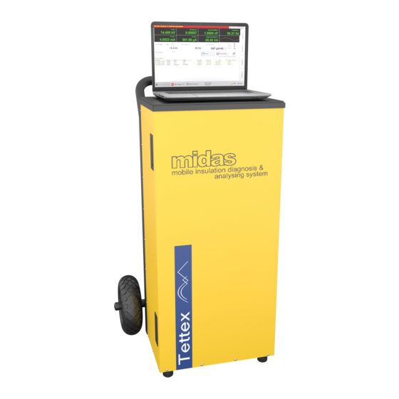
6 Operation Elements Individual Parts The MIDAS system can be dismounted to individual, transportable parts . The system consist of following elements: Measuring Instrument Trolley Laptop These parts can be mounted / dismounted by opening the related fastener. Figure 10 - Individual Parts Operation Elements... -
Page 35: Laptop As System Controller
Laptop as System Controller 6.2.1 Interfaces The supplied Laptop is fully installed with operating system and MIDAS software. The communication between the Midas and the computer is done trough a normal Ethernet connection using the delivered Ethernet cable, the instruments is also equipled with a swiss style mains plug to connect the laptop during measurements. -
Page 36: Instrument Side Panel
Instrument Side Panel The instrument’s right side panel is devided into two main parts: Measuring connections High Voltage and safety ground connections Figure 12 - Side panel 6.4.1 Measuring Inputs The Safety Switch should be used at all times. Never short circuit it and do not use fixed mechanical locking devices for depressing the switch button. -
Page 37: High Voltage And Power Outputs
EMERGENCY STOP BUTTON EXT WARNING LAMP Plug receptacle for connecting optional external safety strobe lamp MEASUREMENT INPUT “A” Plug receptacle for connecting the low voltage test lead MEASUREMENT INPUT “B” Plug receptacle for connecting the low voltage test lead MEASUREMENT INPUT “C EXT”... - Page 38 12. LOW VOLTAGE OUTPUT TO BOOSTER Receptacle to connect the optional current booster type “5287” to extend the supplied test current ( for Inductance testing and short circuit impedance testing) 13. HIGH VOLTAGE OUTPUT Plug receptacle for connecting the high voltage output cable (yellow) respectively the test object Note: The matching plug has a locking ring that should be fastened by hand...
-
Page 39: Hv Gnd Connection Surveillance
HV GND Connection Surveillance The HV GND connection to system ground is kept under constant surveillance. As shown in below, relay Re1 can only close when the test system is supplied with mains power and the test object is earthed via a separate earth connection. Therefore, the high voltage can only be switched on when status “Grounded”... -
Page 40: Emergency Stop
When the MIDAS is permanently housed in a vehicle, the MIDAS ground should be bounded to the vehicle chassis, which in turn is grounded. Exposed terminals of equipment should not normally be allowed to 'float'. They should be grounded directly or through the measuring leads of the MIDAS, unless otherwise specified. Emergency Stop When the Emergency Button is pressed the test is automatically terminated (high voltage is switched off and it is not possible to switch the high voltage... -
Page 41: Software
The MIDAS Software is running on Microsoft Windows 7 Operation System. The software is designed to control all operation and inputs by a Laptop computer trough an Ethernet connection. For instructions about connection between the computer and the Midas 2881 please go to the chapter 6.3 General 7.1.1 Start-up... -
Page 42: Main Window
7.1.2 Main Window The main window consists of four main screens accessible over the related tabs on the right-hand side. Each screen is used for a particular function and are normally used from up to down as following The function of these tab sheets are: Tab Sheet Setup Pressing this button provides access to the definition of the Device under Test (DUT), measuring conditions and auxiliary information. -
Page 43: Title Bar
7.1.3 Title bar The title bar (header line) has following structure: Device Status if Path and Status field Help Button Minimize Close Name operation name of the Button Button mode is actual active “Simulated” file The functional descriptions of the title bar elements are: Device Name Name of the controlled device (MIDAS). -
Page 44: Alarm Messages
It’s strongly recommend to shut down the system correctly before switching the main power off. 7.1.4 Alarm Messages Alarm messages of the system are displayed in the status field. The High Voltage could not be switched on if an alarm messages appears in the status field. The alarm messages can be described as follow: Alarm “Emergency”... -
Page 45: Function Keys
7.1.5 Function Keys The key bar at the bottom of the window consists of the below buttons, some of them only arise in one of the Button “High Voltage ON” By pressing this button the High Voltage is switched on in manual mode. -
Page 46: File Selector Dialog
Button “New” By pressing this button the File Selector Dialog pops up where you can enter a name for the new file. All further measured data will be stored in this file. Button “New based on Template” If this button is pressed the File Selector Dialog pops up and a new test file can be generated which will be based on an existent file. -
Page 47: Report
7.2.2 Report Once the Report button is pressed in the File Manager Dialog two possibilities will arise. Button “Show Report” By pressing this button the Internet Explorer with the actual file will pop up. An example is shown in below. Button “... - Page 48 At the top of the explorer window a small header with three boxes and a print link is placed. With this menu the appearance of the printout can be controlled. It is possible to hide or display the test sequences, the measurement values and the analysis window. Clicking on the Logo on the right side of the explorer window will show or hide the menu.
-
Page 49: Data Format Files
Picture in jpeg format containing the logo for the report. Overwrite the file with Company.jpg your company logo to replace the default Tettex logo. Display of Measurement Values In the tabs sheets “MANUAL” and “SEQUENCE” four measuring values are displayed on top of the screen. - Page 50 The selectable values are: Value Description DF (tan ) Actual measured Dissipation Factor. DF (tan )@20°C Dissipation Factor, temperature corrected to 20°C with the selected Temperature Correction Table. DF%(tan ) Actual measured Dissipation Factor in percentage format DF%(tan )@20°C Dissipation Factor in percentage format, temperature corrected to 20°C with the selected Temperature Correction Table.
- Page 51 PF (cos )@20°C Power Factor, temperature corrected to 20°C with the selected Temperature Correction Table and corrected to line frequency. PF%( cos ) Actual measured Power Factor in percentage format PF%( cos )@20°C Power Factor in percentage format, temperature corrected to 20°C with the selected Temperature Correction Table.
- Page 52 I fe(Rp) Effective iron loss current R Capacitive part of the test impedance (capacitance) Z parallel equivalent circuit R Resistive part of the test impedance (capacitance) Z in parallel equivalent circuit Capacitive part of the test impedance (capacitance) Z in serial equivalent circuit Resistive part of the test impedance (capacitance) Z in serial...
-
Page 53: Tab Sheet Setup
Real Power @ 10kV Real Power (losses, watts) on the test object, normalized to a test voltage of 10kV. 10kV Real Power @10kV = P / (Act. voltage) Act.voltage Ambient Temp. Ambient Temperature. This value is manually set in Menu “Setup: Conditions”... -
Page 54: Menu Dut Info
Menu Settings In this panel, you should enter the current measuring settings, such as cable length used, the parameters of an external capacitor connected and so on. See section “Menu Settings” for more information. Menu Options In this panel, you have the possibility to change the temperature unit (Celsius or Fahrenheit) and the languages. -
Page 55: Menu Conditions (Temperature Correction)
Mandatory Inputs All inputs which are preceded with a red asterisk () are mandatory fields. That means at least one character has to be filled in. This “lock-functionality” can be disabled. See section “Menu Settings“ for more information. If there is an mandatory input field which has to be filled in, the tab sheet button at the top is marked with a red asterisk. - Page 56 With these temperature factors the measured Power Factor and C tan values are normalized to 20°C (68°F), which allows the comparison of results of periodic tests on the same equipment. The temperature corrections are calculated according to ANSI / IEEE C 57.12.80-1999, see following extract.
-
Page 57: Menu Settings
7.4.3 Menu Settings The device configuration data such as length of the cable or accessories used should be entered in this panel. In addition the extended accuracy features are also available on this menu Measuring Cables Input “Length of Measuring Cable [m, ft]” Length and type of measuring cables influence the measurement data, so it is important to set the right length for measuring cable connected to input A, B and HV GND. - Page 58 MANUAL Tab sheet can then be entered in a % value instead of V. Standard Capacitor Cn This option allows using the Midas with an external standard capacitor (e.g. Tettex types 3320 or built-in the Current Booster 5287). The corresponding values of the external nominal capacitor has to be introduced accordlingly.
- Page 59 Text “Value Cn internal” This information shows the value of the internal standard capacitor. The value is set in the factory, or by recalibration, therefore this value should not be modified by the operator. Extended GST Accuracy The stray capacitance between high voltage cable and earth is located in parallel to the test object capacitance and therefore influences the measurements while using the ground input chanel (GST A+B, GST gA, GST gB,...
-
Page 60: Menu Options
Text “Stray DF (tan)” The Dissipation Factor of the measured stray capacitance will be displayed in this field. Check box “Stray Error Correction” By activating this box the capacitance and dissipation factor of the cable stray capacitors will be considered for further measurements. - Page 61 Drop-down list “Language” Here you can select the operating language. Currently available lenguages are English and Chinese. Drop-down list “Start-up Mode” Select Start-up: This button allows you to select the start- up of the system. By pressing this button a list appears, where you can select your start-up mode.
- Page 62 Drop-down list "User Interface"” This option allows to configure the software to be used with a computer keyboard (Standard) or trough a touch screen (Touchscreen) If “Standard” is selected, values introduction in the textboxes are done by typing in the keyboard. For numerical inputs the engineering unit like kilo, nano a.s.o.
-
Page 63: Menu Auxiliary
“REN Password” Here the user has to enter a password to set the system into “Remote controlled” status (together with command REN) from a remote location. This is for safety reasons to ensure that nobody (without the password) can accidentally take over control and switch HV ON. - Page 64 Software...
-
Page 65: Tab Sheet Manual
Tab sheet MANUAL In this mode manual tests can be easily performed. Before doing a test following parameters must be manually selected: connection mode, Applied voltage Frequency. After switching high voltage on, the measuring values can be recorded (stored) in the MEASUREMENTS spreadsheet by clicking the “Record”... - Page 66 Field Set Voltage / Voltage Max This field contains information about the voltage value, which has to be applied to the DUT. The maximum voltage is shown on the top right. For voltages lower than 10 kV and power higher than 1.5 kVA, the maximum voltage should be set below 10 kV to get to power at the test object.
-
Page 67: Tools Window
Button Resonating Inductor Opens a window to set the Resonating Inductor see chapter "Resonating Inductor" Button Signal Analysis See "Menu Signal Analysis" 7.5.1 Tools Window Clicking the “tools” button will open a list with several elements. This list will also pop up if you click the right mouse button somewhere in the tab sheet. -
Page 68: Definition Of Columns For Measuring Spreadsheet
Button Delete Row(s) To delete the actual selected row of the spreadsheet this button can be clicked. If there is more than one row selected, all of them are deleted. Button Signal Analysis Pressing this button will open a window, where you get more information about the measured signal. -
Page 69: Formulas In Measuring Grids
This dialog is used to define the recorded measured data. With selected measuring values can be added or removed from the active spreadsheet. With all data can be moved or removed. With you can move the position of a specific active column. Note: The columns in the measuring spreadsheet itself can also be moved in position with simple drag and drop. - Page 70 Use Define Formula to define the title, formula and the unit of the column Formula Title column title Formula Enter the formula of the cell of column Formula, when a measurement is recorded. Where C[0,0] is the actual cell. C[-4,-1] means 4 columns leftside of column ∆tanδ. This is cell DF(tanδ) and one row above the actual row.
-
Page 71: Menu Signal Analysis
7.5.4 Menu Signal Analysis Additional information about the measured signals like wave shape and spectrum analisys is available in this menu. This information has no influence for analysing the test object . You will get in this menu, when you press Tab Sheet Spectrum This tab sheet will show you the spectrum of the measured signals. - Page 72 Tab Sheet Scope This mode act as an oscilloscope showing the input signals in function of time. Sampling rate is 48kHz (one sample every 20.83 μs). Y exe shows the input signal amplitude in ADC counts. The maximum number of counts is 2 (6’388’608) Button description: Button Up / Down Amplitude...
- Page 73 All Signals: Shows I Reference Test Mains, Apex Check box Lissajous If this option is marked, the "I Ref (Cn)" Channel is shown as a function of the test channel "I test (Cx)", instead of as a function of the time. Button Difference Activating this option will show the difference between Channel "I Ref (Cn)"...
- Page 74 Buttons description: Button X / Y Axis By pressing this button the measuring values for the x- or y-axis can be chosen. If you select "Index" as axis, the values are shown in order which they are recorded. Button Clear Curve Pressing this button will clear the scope.
-
Page 75: Tab Sheet Sequence
Tab sheet SEQUENCE Via this sheet a complete test cycle can be created. The whole process is designed in such a way that modifications can be done quick and straight forward. The tab sheet “SEQUENCE” consists of two sections. At the top half of the window a test sequence can be defined by the voltage applied, the test mode (UST or GST) and a picture with some comments. - Page 76 Column SqNr Identification number of the sequence. Column Description Description of measurement. For example the object where the High Voltage Source is connected. Column Voltage Voltage applied to the test object. Column Frequency Frequency of the AC voltage applied to the test object. Column UST A …...
- Page 77 Button Sequence Info Button Sequence Info Pressing this button will open a dialog with the information contained in the column “Bitmap” and the column “Text”. Button Sequence Tool Button Sequence Tool By pressing this icon a pop-up list appears with the following buttons. Button Edit This button will open a numerical or alphanumerical input for editing the content of the cell.
-
Page 78: Sequence Measurement
Sequence Dialog With a valid bitmap and text, a dialog appears before the voltage is applied. An example is shown below. This dialog pops up after pressing . The sequence may be continued by pressing , or interrupted by . During the whole dialog the high voltage is switched off. 7.6.2 Sequence Measurement In the second half of the tab sheet SEQUENCE the measured values of a sequence are stored. - Page 79 Button Define Columns This button can be used to define which data will be displayed. Button Show Comment Pressing this button will show the action of a limiter: whether the value exceeds the limiters or not. Button Edit Comment Pressing this button will open an alphanumerical dialog, where you can enter a comment for this measurement.
-
Page 80: Edit Sequence Limiters
7.6.3 Edit Sequence Limiters By pressing , a dialog appears in which the “atention” and “Pass” limiters can be modified. These limits are defined as yellow (Atention) and green (pass) areas in the analisys chart in the analisys folder. Limits can be defined as absolute or relative (in porcentage) to the expected value. When defining limits, first the attention area has to be defined. - Page 81 Column Value This data is the reference value of the limits Column Rel If the option is activated “MinTol” and “MaxTol” are relative to the reference value , otherwise the inputs are absolute. Column MinTol This field indicates the minimum tolerance level of the “Pass” or “Attention”...
-
Page 82: Starting Sequence
Button Edit By pressing this button the selected cells such as value, MinTol, MaxTol can be edited. Button Apply to all If this button is clicked, the current measured value with its limiters will be applied to all limiters. Button Add Pressing this button will add a line to the spreadsheet. - Page 83 Button Start At Selected Pressing this button will start the sequence at the selected row of the spreadsheet SEQUENCE. Software...
-
Page 84: Sequence With External Ac Power Source
7.6.5 Sequence with External AC Power Source The SEQUENCE tool can also be used with an external AC power source. To do so the option “use external AC source” in the settings folder must be activated. When active, and after clicking the “start sequence” button, the “Catch Value” window guides the user over the necessary voltages to complete the sequence. -
Page 85: Tab Sheet Analysis
Tab sheet ANALYSIS In this sheet you can compare the new measured data with older ones for trending visualisation or display a measured value against another, for example dissipation factor against voltage. 7.7.1 Spreadsheet Measurement Button Analysis Columns With the buttons at the top of the spreadsheet, you can change the amount of displayed measuring data. -
Page 86: Graphic Analysis
Button Show Comment Pressing this button will show the action of a limiter: whether the value exceeds the limiters or not Button Edit Comment Pressing this button will open an alphanumerical dialog, where you can enter a comment for the measurement. Button Delete Row(s) Pressing this button will delete the actual selected measured data. -
Page 87: More Analysis
Button Rename View Pressing this button will rename the actual view. Button Delete View Pressing this button will delete the actual selected view. Button Set Current View Pressing this button will store the current view under the actual selected name. 7.7.3 More Analysis This tool is used to analyze several files at the same time. -
Page 88: Remote Operation
Button Save List As Pressing this button will store the actual list in a file. Button Load List Pressing this button will load a list from a file. Button Show Analysis Pressing this button will open a dialog with all files from the list. -
Page 89: Characteristics Of The Interface
7.8.1 Characteristics of the interface The settings can be seen in the tap sheet SETUP / Menu Options Command Syntax The command syntax corresponds to the IEEE 488.2 standard. The following list is an explanation of the terms, special characters and rules of syntax. Terms, Characters Explanation Remarks... - Page 90 <NR3> Real numbers with exponents 1.56E+1, -1.67E-12 <String> Character sequences without CTRL 'Test character sequence' (ASCII 13) and LF (ASCII 10) (see also the “Command Syntax” section). <ARBITRARY ASCII Character sequences of indefinite length, abcdefg..z and even RESPONSE DATA> closed by the end character. more<EOS>...
- Page 91 Is used to mask the ESR. If a bit is set to '1', an associated bit in ESR can be set *ESE and can initiate a collective alarm, otherwise nothing. Event Status Enable Register Internal Status Register Set if a transmission error (time out) occurs. Set if the device is in the 'local' state.
-
Page 92: General Commands
Holds the last error queried. No error Query Error Buffer overflow either for input or output Register Most of the commands have a short form and a long form. Short forms are written in upper case characters. The part of the command header written in upper case has to be transmitted so that the MIDAS can recognize the command. - Page 93 *STB? <NR1> Calls up and then deletes, with exception of the MAV bit, the contents of the status register masked by the service request enable. Remotely controlled via the IEEE 488. Can also query the contents via serial poll. In this case bit 6 identifies the state of the RQS line instead of the Master Summary Status.
-
Page 94: System Control Commands
HELP? <ARBITRARY Returns the available command headers. ASCII RESPONSE DATA> FILE? <String> Returns the actual working file. SAVE <String> Stores the current working file under the name <String> . Sets bit 1 at the “Device Dependent Register” in case of an error. Example.: SAVE 'C:\ABC.XML' LOAD <String>... - Page 95 MAXV <Nx> X X Sets or returns the maximum allowed voltage. The value should be between 0V and 15 kV otherwise the EXR MAXV? Register will be set to 5. <Nx> X X Sets or returns the target value of the frequency.
-
Page 96: Measurement Commands
TYPE <string> X X Sets or returns the type of the insulation. TYPE? If you want to set the insulation type, <string> has to be a member of the temperature correction file. See section “Menu Condition” for more information. Otherwise the DDR Register will be set. Example INSUL:TYPE "Liquids :Askarel"... - Page 97 DF20? <Nx> X Dissipation factor with temperature correction. Answer similar as "0.0043 " <Nx> X Power factor without temperature correction. Answer similar as "0.0043 " PF20? <Nx> X Power factor with temperature correction. Answer similar as "0.0043 " CAPX? <Nx> X Test Capacitance C in parallel equivalent circuit Answer similar as "12.34 pF"...
-
Page 98: Alarms
<Nx> X Complex Admittance of the test object Answer similar as "|5.841E-08|89.92°" MeasSET <String> X X X Allows to define a set of measuring data, which all be transferred by the command "MeasDATa". All data belong to one calculation and are recorded at the same time. Each values is separated by a comma. - Page 99 HVGnd? X Signals "YES" if High Voltage Ground is not connected. ANY? Signals "Yes" if any of the alarms above is set to true. Software...
-
Page 100: Accessories And Options
8 Accessories and Options Office Software The MIDAS Office Software package contains the normal MIDAS operation software which can be installed on a standalone office PC or notebook. The software is used for test preparation, data collection, exchange and analysis, staff education and training , etc. Safety Strobe Light With an external safety strobe light (optional warning lamp) it is possible to position a second high voltage indicator where all... -
Page 101: Resonating Inductor
Resonating Inductor General The capacitive load range covered by the MIDAS system can be increased using a Compensating Reactor (resonating inductor). Capacitance (DUT) to be measured Standard capacitor N int. Test voltage, applied to the test Test object Compensating reactor for test current extension Measuring shunt on the DUT side... -
Page 102: Kv Resonating Inductor 5288A
8.4.1 10kV Resonating Inductor 5288A The capacitive load range covered by the MIDAS system can be increased using the Resonating Inductor. Option “Resonating Inductor 5288A” The following items are supplied with this option: Inductor 5288A High voltage link cable to MIDAS, 3m Specification Rated Voltage 10 kV @ 50/60Hz... - Page 103 Schematics Overview of the 5288A inductor and it’s shielding Operation Activate the use of a Resonating Inductor in the Menu "Menu Settings" Accessories and Options...
- Page 104 Press in menu "Manual" to activate the inductance visualisation display on the MIDAS to support the tuning of the resonating inductor. Rotate lever to “Unlocked” position and coarse-balance using the hand wheel and the analogue scale on the frontpanel of the inductor Set voltage in the range of 500 V ..
-
Page 105: Kv Resonating Inductor 5289
It is designed to use together with the Tettex MIDAS system, which capacitive load range can therefore be increased. Incorporated in a rugged housing on wheels it is suitable for lab and field use. - Page 106 Operating and Connection Elements Figure 2: Top-panel of the Inductor with operating elements Description L+ button, press to decrease the core air gap respectively increase the inductance value L- button, press to increase the core air gap respectively decrease the inductance value Supply connection.
- Page 107 Connection Make sure the power of both the Midas and the Resonating Inductor 5289 is Switched OFF before connecting them together. The earth cables should be the FIRST leads to be connected to the equipment. The unit itself is also earthed over the outer shield of the HV Input cable and the PE pin of the mains cable. The Midas must be switched ON FIRST –...
- Page 108 Figure 3: Rotating Machine Stator Test connections to Midas using the resonating inductor and the baseload capacitor. With UST B the baseload can be checked, with UST A the connected rotor capacitance is measured. Accessories and Options...
- Page 109 Schematics Overview of the 5289 inductor and it’s shielding Accessories and Options...
- Page 110 Operation Activate “Resonating Inductor” in the Midas Menu “Settings” Press in menu "Manual" to start the resonance balance display. Here you can supervise how to adjust the resonating inductor. On the top Line you get the blue instruction fields how to tune the Inductor (Press L+ or Press L-). The phase shift should be as small as possible (<...
- Page 111 Disable the Resonating Inductor checkbox in menu "Setup" to reactivate the Midas high voltage transformer over current protection (which is disabled while 5289 operation) Set the inductance gap back to a medium position. This protects the end position switches and also the core of the inductor against mechanical wear.
-
Page 112: Current Booster
Current Booster The max. output current of the MIDAS system can be increased by using a Current Booster (transformer). The output voltage is reduced to 100V (10V) while the possible current is boosted up to max. 10A. This unit is normally used for short circuit impedance testing on power transformers. - Page 113 length, Cn ext data). The voltage control field now uses a % input field which correspond with the 10V respectively 100V booster output level. The following items are supplied with this option: Current Booster 5287 High current connection cable to DUT with clamp, 20m Link cable to MIDAS low voltage output, 2m Link cable to MIDAS C and V connectors, 2m...
-
Page 114: Care And Maintenance
Care and Maintenance The MIDAS Measuring instrument is basically service free, as long as the specified environmental conditions are adhered to. As a result, service and maintenance is restricted to cleaning of the equipment and calibration at intervals stipulated by the application for which the instrument is used. The insulation of all high voltage cables should be periodically checked for damage. -
Page 115: Instrument Storage
9 Instrument Storage During day to day use the instrument can be switched off at the mains switch located above the mains socket on the rear panel of the instrument. If the instrument is to remain unused for any length of time, it is recommended to unplug the mains lead. -
Page 116: Packing And Transport
10 Packing and Transport The packing of the MIDAS C tan Measuring instrument provides satisfactory protection for normal transport conditions. Nevertheless, care should be taken when transporting the instrument. If return of the instrument is necessary, and the original packing crate is no longer available, then packing of an equivalent standard or better should be used. -
Page 117: Recycling
11 Recycling When the instrument reaches the end of its working life it can, if required, be disassembled and recycled. No special instructions are necessary for dismantling. The instrument is constructed of metal parts (mostly aluminum) and synthetic materials. The various component parts can be separated and recycled, or disposed of in accordance with the associated local rules and regulations. -
Page 118: Trouble Shooting
Customer Support Department of HAEFELY TEST AG or your local agent. The Customer Support Department can be reached at the following postal address: HAEFELY TEST AG Customer Service - Tettex Lehenmattstrasse 353 CH-4052 Basel Switzerland... -
Page 119: Conformity
13 Conformity Conformity... -
Page 120: Appendix
Appendix Appendix... -
Page 121: Applications Guide
14 Applications Guide This chapter contains important information regarding construction of the test circuit and the individual test modes depending on the device under test. Selected circuits for specific test objects are presented for further information. Unfortunately it is not possible to provide a test circuit for every customer specific test object as this would exceed the capacity of this manual. - Page 122 A bushing without a potential tap or power-factor tap is a two-terminal device which is normally tested overall (center conductor to flange). If the bushing is installed on equipments like circuit breaker, transformers or cap banks the overall measurement will include all connected and energized insulating components between the conductor and ground.
-
Page 123: Spare Bushings
Hot Collar Test (Collar to Center Conductor) Due to the caution statement mentioned above, it is important to note that for tap-insulation tests the applied voltage should not exceed 5 kV for potential taps and 500 V for dissipation factor taps. For the overall and the center conductor to tap test a convenient voltage at or below the bushing nameplate rating should be chosen. -
Page 124: Installed Bushings
The tap insulation (C2) of bushings equipped with taps, can be measured directly. As illustrated in the figure beside, the High Voltage and the INPUT A cable must be interchanged. Using the GST gA+B mode will bypass the main insulation (C1) and measure the tap insulation (C2). - Page 125 The C1 insulation is measured by the UST A mode. The connection is shown in the figure beside. The values are measured in the conventional manner, and the dissipation factor is calculated and corrected for temperature. For a bushing in a power or distribution transformer the average temperature of the...
- Page 126 In analogy to the tap insulation test on spare bushings the C2 insulation is measured by the GST gA+B mode. The connection is shown beside. For the capacitance C2 (tap to flange) the dissipation factor is calculated but normally not corrected for temperature.
- Page 127 Variable Frequency Test (DFR) This test consist of the measurement of the capacitance and tan delta at diferent frequencies and plotting the values against the frequency, connection diagram is the same as for C1 measurement. Frequencies selected should be at least between the 15Hz and 400 Hz, higuer frequencies can be measured if device is capable of.
-
Page 128: Measuring Data Interpretation
14.1.3 Measuring Data Interpretation Condenser Bushings The dissipation factor and capacitance recorded are compared with one or more of the following: Nameplate data. Results of prior tests on the same bushing. Results of similar tests on similar bushings. Dissipation factors for modern condenser bushings are generally in the order of 0.5% after correction to 20°C. -
Page 129: Transformers
The losses recorded should be less than 100mW. If the current or watts-loss is appreciably higher than normal, then a second test is made after moving the collar down one petticoat. This procedure can be followed as far down the bushing as necessary to determine how far down the fault has progressed. - Page 130 The decision about the applied test voltage is in most cases easy since the tested equipment is generally rated above 15 kV. In case of equipment rated 15 kV or lower, consideration should be given to include testing at slightly above (10..25%) the operating line-to-ground voltage. IEEE C57.12.90 recommends that, for insulation dissipation factor tests, the voltage should not exceed one-half the low-frequency test voltage given in IEEE C57.12.00.
- Page 131 Two Winding Transformers (3 phase and single-phase) Measurement connections of a two windings transformer for measurement of C and C Test Connections Sequence INPUT A INPUT Test Mode High Voltage Line HV GND Tank GND UST A Tank GND GST gA+B Tank GND GST gA+B Tank GND...
- Page 132 Autotransformers (3 phase and single-phase) Contrary to the two-winding transformer the windings of an autotransformer can not be separated. The winding of an autotransformer is a combination of the high- and low-voltage windings (HV and LV, see figure below). For testing the insulation of an autotransformer all seven bushings (three bushings for a single-phase unit) have to be connected together (HV1+HV2+HV3+LV1+LV2+LV3+0).
- Page 133 Three Winding Transformers (3 phase and single-phase) The test technique for a three-winding transformer is an extension of the two-winding transformer test procedure. In some cases a three-winding transformer is so constructed that one of the interwinding capacitances is practically non-existent. This condition may be the result of a grounded electrostatic shield between two windings, or of a concentric-winding arrangement which places one winding between two others.
- Page 134 Measuring Data Interpretation If available the dissipation factor and the capacitances should be compared with factory data, with previous test results and with test results on similar units. Capacitance is a function of winding geometry, and is expected to be stable with temperature and age.
-
Page 135: Shunt Reactors
14.2.2 Shunt Reactors Oil-filled shunt reactors are used in HV systems to limit over-voltage surges associated with long transmission lines. The shunt reactor compensates the capacitive generation on power lines to avoid non-controlled voltage rise especially on lightly loaded lines. Two configurations of shunt reactors are available: either each phase is contained in its own separate tank or all three phases are contained in a common tank. -
Page 136: Current Transformers
Sometimes it is advantageous to investigate abnormal results by making a series of tests at several voltages, to determine if the condition causing the abnormal result is nonlinear or voltage sensitive within the range of available Test Levels. This might include increasing the test voltage up to 15kV. 14.2.3 Current Transformers Current transformers (CTs) convert high transmission line current to a lower, standardized value to be handled by instrumentation. -
Page 137: Voltage Transformers
14.2.4 Voltage Transformers A huge variety of different kinds of voltage (or potential) transformers makes a complete disquisition in this manual impossible. Therefore only one of the most famous and widespread voltage transformer is presented here. It is the capacitor voltage transformer (CVT) as available for example by ABB (type CPA) or by Trench (type WE). -
Page 138: Short Circuit Impedance
Capacitor voltage divider Tuning reactor Primary winding Secondary winding Ferro resonance damping winding Capacitor voltage transformer test procedure Test Connections Test Mode High Voltage INPUT A INPUT HV GND || C GST gA+B Measuring Data Interpretation Measurement results should be compared with earlier measurements on the same apparatus, on similar units and with manufacturer data. -
Page 139: Measurement Procedure
The short-circuit impedance (Z ) is defined as the corresponding impedance to the voltage short-circuit ) that must be connected to one pair of terminals of a transformer with another pair of terminals shorted, which causes rated current (I ) to flow on the two sides of the transformer. rated short-circuit rated... -
Page 140: Excitation Current Measurement
According to the number of phases and the vector group the displayed short circuit-impedance must be multiplied or divided by √3: Single Phase Star connection Delta connection R = Rs (Zx=Ls+Rs) R = Rs (Zx=Ls+Rs) / √3 R = Rs (Zx=Ls+Rs) ·√3 X = Ls (Zx=Ls+Rs) X = Ls (Zx=Ls+Rs) / √3 X = Ls (Zx=Ls+Rs)·... - Page 141 Excitation current measurement connection for L and L measurement on a D-Yn transformer Test Connections DUT, excitation High Voltage INPUT A INPUT B HV GND INPUT Test Mode current through Tank GND UST A Tank GND UST B Tank GND UST A Tank GND UST A...
-
Page 142: Rotating Machines
Difference between the two higher currents Difference between the two higher currents should should be less than 10% be less than 5% In general, if there is an internal problem, the differences between the phases with the higher current will be greater. When this happens, other tests should also show abnormalities, and an internal inspection should be considered. -
Page 143: Measuring Data Interpretation
Rotating Machine Stator Test connections to measure C and C Test Connections INPUT A INPUT B INPUT Test Mode High Voltage HV GND Casing GST gA+B Casing UST A Casing UST B Casing UST B Casing GST gA+B Casing GST gA+B Casing GST gA+B 1 + 2 + 3... - Page 144 The ungrounded specimen tests between phases with a voltage below corona-starting voltage can give some indications about general deterioration, moisture or dirt. Because the stator iron shields the slot sections of the phases from one another, the inter-phase test becomes essentially a test of the exposed end-turn insulation which is affected most by atmospheric contamination.
-
Page 145: Measuring High Cap Values Using The Resonating Inductor
14.3.3 Measuring high cap values using the Resonating Inductor When testing large generator windings which have a very high value of capacitance per phase, the MIDAS hits limits as it cannot supply the charging current requirements. With the MIDAS built-in supply, capacitances up to a maximum of : = 127nF ( 50Hz, @10 kV S = 4kVA) -
Page 146: Operation Of Resonating Inductor With Midas
14.3.4 Operation of Resonating Inductor with Midas Before connecting the resonating inductor with Midas it’s best to switch off both Midas and the resonating inductor. The short HV cable delivered with the resonating inductor should be connected to the HV output of Midas and the HV input of the resonating inductor. The HV cable delivered with the Midas unit should be connected to the HV output of the resonating inductor. -
Page 147: Liquid Insulation
Balance’ should be adjusted to make sure that the balance pointer stays in the green zone (to keep the resonance inductor in proper resonance). The ‘Resonating Inductance Balance’ display which button (L+ or L-) should be pressed to return to a proper balance. When measuring relatively low capacitance values at high voltages, with the resonance inductor (e.g. -
Page 148: Measuring Data Interpretation
should be selected. By choosing the normalized dissipation factor (to 20°C) as a measuring value the automatically calculated value will be recorded. The Liquid Insulation Test is made by normal UST A mode. Instead of the HV GND input the Input A is used as low voltage to reach the highest possible accuracy. -
Page 149: Cables
The question of what decision to make regarding the condition of the oil depends upon what is causing the high dissipation factor. Dielectric breakdown or water content tests should be made to determine the presence of moisture. The necessity for further tests will depend to a large extent upon the magnitude of the dissipation factor, the importance of the apparatus in which the insulation liquid was used, its rating, and the quantity of insulation liquid involved. -
Page 150: Test Procedure Example
3 Phase Unshielded Cables Enclosed in a Common Metallic Sheath Each conductor of an unshielded three phase cable should be tested individually with the other conductors and the common sheath grounded. An overall test can be made with all conductors connected together and energized with the sheath grounded. -
Page 151: Measuring Data Interpretation
Note: On 3 Phase Individually Shielded Cables only the capacitances C1G, C2G and C3G are measured in the same manner as described in the table above. 14.5.3 Measuring Data Interpretation Temperature correction of the dissipation factors for cables is normally not made, since it requires a fairly close approximation of cable temperature, knowledge of the type of insulation and the date of its manufacture. -
Page 152: Measuring High Cap Values Using The Resonating Inductor
Measurement on an ungrounded two-bushing energy storage capacitor, connection for determination of C main capacitor : earth insulation capacitance Test Connections High Voltage INPUT A HV GND Test Mode UST A Tank GND GST gA+B Tank GND GST gA+B 1 + 2 Tank UST A 14.6.1 Measuring high cap values using the Resonating Inductor... -
Page 153: Circuit Breakers
Measurement of a grounded two-bushing energy storage capacitor with additional resonating inductor, connected for C determination. Test Connections High Voltage INPUT A HV GND Test Mode Tank GND UST A Tank GND GST gA+B Tank GND GST gA+B 1 + 2 Tank UST A Measuring Data Interpretation... - Page 154 = [110% .. 125%] x U /√3 test rated As the internal AC power source of the MIDAS system can supply maximum 12kV/15kV, the insulation tests of breakers rated above 23.6kV are performed at 12kV/15kV. Depending on the nominal line voltage, operating mechanism (spring, hydraulic) and arc-quenching medium (air, oil, sulphur hexafluoride) circuit breakers are sometimes designed with two or more series connected interrupting chambers.
-
Page 155: Dead Tank Breaker
14.7.1 Dead Tank Breaker The test connections for a Dead Tank Breaker (e.g. ABB PASS type) is outlined below: Dead Tank Breaker measurement connections for measurement of C and C contact insulation capacitance earth insulation capacitance Test Connections INPUT A INPUT Test Mode High Voltage... -
Page 156: Live Tank Breaker
14.7.2 Live Tank Breaker The test procedure for a Live Tank Breaker (e.g. SIEMENS 3AP1 type) is shown below: Live Tank Breaker measurement connections + (PS bushing stray capacitances (undrawn) + (PS : grading capacitors insulation column capacitance breaker switches , PS : pre insertion switches pre insertion resistors... -
Page 157: Measuring Data Interpretation
14.7.3 Measuring Data Interpretation The specific term “Tank-Loss Index (TLI)“ was introduced to assist in evaluating the results of the open and closed circuit breaker tests. The TLI index is defined as the real power difference of the measured open circuit and closed circuit for each phase. The open circuit real power value consists of the individual values measured on the two bushings of each phase. -
Page 158: Test Procedures
The following table gives an overview of recommended Test Levels for several surge arresters. Arrester Type Arrester Unit Rating Test Voltage [kV] [kV] Silicon Carbide 9.0 / 10.0 12.0 and above Metal Oxide 2.7 to 3.0 4.5 to 12.0 15.0 and higher 10.0 14.8.2 Test Procedures Surge arresters can be equipped with leakage-current detectors or discharge counters. - Page 159 Applications Guide...
-
Page 160: Measuring Data Interpretation
Test Procedure on a Multi-Unit Arrester Stack Assemblies consisting of three units or more per phase are tested in the manner outlined in figure 53 on the next page. Again, the line is de-energized and grounded then disconnected from the arrester stack. -
Page 161: Index
M I D A S 2 8 8 0 Delete View 78 Index Difference 64 Edit 68, 73 Edit Comment 70, 77 Edit Description 58 Edit Limit(s) 68 Evaluate Parameters 49 A Ext. Noise Reduction 35 Extended Noise Reduction 57 Alarm File Manager 35 Emergency 34... - Page 162 Save As 36 use Booster 5287 48 Save List As 79 Check box Selection of measuring values 55 use external Standard Capacitor Cn 48 Sequence Info 68 Check box Sequence Tool 68 Stray Error Correction 50 Set Connection 55 Check box 50 Set Current View 78 Check box Set Frequency 56...
- Page 163 M I D A S 2 8 8 0 D Connection 43 Cp (parallel) 42 Device Name 33 Cs (serial) 42 Device Name 33 DF 40 Document Name 33 DF @20°C 40 Drop-down list DF% 40 Language 51 DF%@20°C 40 Line Printer 52 Frequency 41 Startup Mode 51...
- Page 164 Minimize Button 33 P Parallel Capacitance Detection 50 S S / N Ratio 41 Simulation Mode 33 Status Field 33 T Tab Sheet Analysis 32 Attention 72 Auxiliary 44 Conditions 43 DUT Info 43 Manual 32 Noise Channel 62 Options 44 Pass 72 predefined Views 77 Reference Channel (Cn 62...
Need help?
Do you have a question about the MIDAS 2881 and is the answer not in the manual?
Questions and answers