Table of Contents
Advertisement
Advertisement
Table of Contents

Related Manuals for Tettex 2293

Summary of Contents for Tettex 2293
- Page 1 Operating Instructions HAEFELY TEST AG 2293 Winding Analyser Version 1.9 4842186...
- Page 2 Title Operating Instructions 2293 Winding Analyser Date 07-2011 Authors MM, LWA, SG, SM Layout Part number 4842186 Revision History V0.9 06/2011 Initial release of the document V1.0 07/2011 Additional features added, manual completed V1.1 03/2012 Remote control chapter added V1.2...
- Page 3 WARNING Before operating the instrument, be sure to read and fully understand the operating instructions. This instrument produces hazardous voltages. It is the responsibility of the user to ensure that the system is operated in a safe manner. This equipment contains exposed terminals carrying hazardous voltages.
- Page 4 Manual Conventions In the manual, the following conventions are used: Indicates a matter of note. If it refers to a sequence of operations, failure to follow the instructions could result in errors in measurement. Indicates hazards. There is a risk of equipment damage or personal injury or death. Carefully read and follow the instructions.
- Page 5 Foreword Welcome as a new user of the “Winding Analyzer 2293”. Thank you for placing your confidence in our product. With the purchase of this measuring instrument you have opted for all the advantages that have built a world-wide reputation for a Tettex Instrument: robustness, performance and quality is assured. As a result this instrument provides a solution which achieves the optimal combination of traditional know- how and leading edge technology.
-
Page 6: Table Of Contents
Contents Introduction Receiving Instructions .................. 9 General ......................9 Scope of Supply ................... 9 1.3.1 Standard scope of supply ..............9 1.3.2 Options and accessories ............... 10 Optional features ..................10 Technical Data ................... 12 1.5.1 Standard Features................. 12 1.5.2 Physical and Environmental Specifications ........ - Page 7 Connection Cables ..................32 5.1.1 Cable extensions (optional) ............33 Connecting the Instrument ................. 33 5.2.1 Connection without extenders ............34 5.2.2 Connection with extenders ............34 5.2.3 Connection in Automated mode to a 3 phase transformer .... 35 5.2.4 Connection in Automated mode to a 1 phase transformer ....
- Page 8 Performing a test using Classic mode ............67 7.5.1 Test object connection on classic mode ........67 7.5.2 Set up DUT data ................67 7.5.3 Temperature correction ..............67 7.5.4 Test current selection ..............68 7.5.5 Auto recoding configuration ............69 7.5.6 Measurement ................
- Page 9 Transformer configuration Detection 11.1 Overview ....................97 11.2 User Interface .................... 97 11.2.1 Active Window ................100 11.2.2 Function keys ................100 11.3 Performing a Detection ................101 11.3.1 Measurement steps ..............101 11.3.2 Parameters definition ..............101 11.3.3 Detection ..................101 11.3.4 Export results ................
- Page 10 13.5.1 Measurement steps ..............135 13.5.2 Set up DUT data ................. 135 13.5.3 Data handling definitions ............. 136 13.5.4 Test Voltage Selection ..............136 13.5.5 Test frequency selection ............. 137 13.5.6 Magnetic Imbalance selection ............. 137 13.5.7 Delta Winding Configuration selection ......... 137 13.5.8 Measuring ...................
- Page 11 15.4.8 Miscellaneous ................165 15.4.9 Measuring ................... 165 15.4.10 Measurement results ..............166 15.4.11 Exporting and printing ..............167 Optional Features activation 16.1 Software key Activation ................168 Tap Changer Interface 17.1 General ....................170 17.1.1 Tap changer remote operation signal .......... 170 17.1.2 Tap changer feedback signal ............
- Page 12 Remote Control 22.1 Ethernet Connection ................182 22.1.1 RJ45 Socket ................182 22.1.2 Direct connection................. 182 22.1.3 Switched Network................ 184 22.1.4 Routed Network / Internet ............184 22.2 Protocol ....................185 22.2.1 Instructions .................. 186 22.3 Command Reference ................187 22.4 Programming examples ................
-
Page 13: Introduction
General The Tettex 2293 is the result of extensive research and years of experience testing transformers. It incorporates a fast and highly advanced procedure to measure winding resistance. A simple one-time-connection system together with the simultaneous winding magnetization method drastically reduces measuring time. -
Page 14: Options And Accessories
For detailed information about accessories and options please refer to the chapter 21 “Accessories and spares” Optional features The 2293 is equipped with optional features. These optional features can be enabled using the license manager. . For getting licenses for new features contact our sales department (sales@haefely.com) - Page 15 Trial licenses for a number of tests are available under request. Contact our sales department to get a trial code. Introduction...
-
Page 16: Technical Data
Technical Data 1.5.1 Standard Features 8 measuring channels (2 x 3 phases and 2 x 1 neutral) 6 temperature channels with automatic resistance correction High efficient DC supply with SWM (simultaneous winding magnetization) SWM mode and Classic mode (for traditional resistance measurement method) ... -
Page 17: Ratio Measurement
320 μ … 32 k 0.1% 32 k … 320 k (1) at temperature -10 …+60°C at highest available current Current 3.2A 320mA ±0.1% 100V 32mA 10mV 3.2mA ±1% 320μA Resistance 1.5.4 Ratio Measurement General ≈ 700 mA Max. Supply Current AC Peak ≈... -
Page 18: Temperature Measurement
1.5.5 Temperature Measurement Built-in Channels 30 (6 internal + 3x external 8CH box “2293T”) Max. Meas. Channels Sensor Probe PT100 Class A Temperature Accuracy -20°C … +150°C ± (0.41°C + 0.2% T Meas 1.5.6 User Interface System 7” graphical touch screen interface Memory: >10'000 measurements Communications:... -
Page 19: Interlock Interface (Optional)
1.5.9 Interlock Interface (optional) Function Connect an external contactor of interlock circuit Connector Socket: LEMO2 (2P ERA 1S) Plug: LEMO2 (FFA 2S 302 CLAC62 2P) Ratings Max. 5V, 100mA 1.5.10 Covered Standards CE mark Compliant Standards IEC 61010, General IEC 61326-1, IEC 61000-4-X, 61000-3-X, EN 55011, ANSI/IEEE C37.90 Safety VDE 0411/part 1a , IEC/EN 61010-1:2002... -
Page 20: Safety
Do not operate the 2293 from a variable power supply. The 2293 adjusts to the local line voltage at start-up. Changing the line voltage while the unit is in operation may cause... -
Page 21: Essential Safety Recommendations
(for example a door is opened). The interlock is an additional (optional) input in the 2293 front panel to be connected to the factory/fences safety circuit that encloses the high-voltage zone. It sends an electrical signal and read the return, if the return is not there, an alarm message arise in the screen and test cannot be started or are interrupted if running. -
Page 22: Summary
To avoid damaging the device due to induced overvoltage’s or wrong connections, the Interlock input of the 2293 has to be connected to the safety circuit only by using a relay contact trough short screened cables. Opening the Interlock doesn’t mean a safe situation by itself, as the test object (transformer) has been charged while measuring and stored energy has to be removed. - Page 23 possibility of getting on a live circuit. To avoid this requires constant vigilance - for oneself and for one's fellow workers. In addition to the obvious dangers, personnel should be alert to recognize subtle dangers as well. For example, during transformer excitation-current tests, the floating terminals may have significant voltages induced in them by simple transformer action.
-
Page 24: Theory
Theory General Resistance Measuring Principle Basically the instrument consists of 3 programmable power supplies, which can operate in constant current or constant voltage mode. Further, these power supplies operate in two quadrants. This means that a power supply can act as an active load, which is used to quickly discharge the current from high inductive DUT. -
Page 25: Power Supply Modes
Power Supply Modes The 3 power supplies in the 2293 can operate in different configurations. These programmable configurations will be explained in this chapter. 3.2.1 Parallel Mode on HV-side 16A ¦ 100V (A1) or 32A ¦ 50V (A2) This supply... -
Page 26: Parallel Mode On Lv-Side 16A ¦ 100V (B1) Or 32A ¦ 50V (B2)
Current Active Load Supply Region Region (Discharging) (Charging) 800W 400W The following diagram shows the operating area for power supply in mode A2 and B2 - 32A ¦ 50V: Current 800W Active Load Region (Discharging) Supply Region (Charging) 400W 3.2.2 Parallel Mode on LV-side 16A ¦ 100V (B1) or 32A ¦ 50V (B2) This supply mode is selected, when a phase on the low voltage side of the transformer has to be measured without the corresponding phase on the high voltage side. - Page 27 32A / 50V 16A / 100V The measured resistance is calculated as follows: The transformer transforms any inductive voltage applied to the low side to a higher voltage on the high voltage side (the resistive voltage drop is not transformed!). For this reason, the device senses the voltage on the high voltage side and limits it by controlling the supplies on the low voltage side accordingly.
-
Page 28: Individual Mode 2X 16A ¦ 50V (C)
3.2.3 Individual Mode 2x 16A ¦ 50V (C) This supply mode is selected, when two the corresponding phases of the high and low voltage side of the transformer have to be measured. The three power supplies are split to the HV and LV side. - Page 29 Theory...
-
Page 30: Yndx Mode 2X 16A ¦ 50V (D)
3.2.4 YNdx Mode 2x 16A ¦ 50V (D) This supply mode is selected, when two the corresponding phases of the high and low voltage side of an YNdx (x = 1, 3, 5, 7, 9, 11) transformer have to be measured. This mode is on applicable to YNd transformers. -
Page 31: Measuring Sequences
DUT is an YNd transformer and the current is less or equal 16.0A. YNd measuring mode must be set to “without Rn (Ph-Ph)”: The following examples show the measuring sequence generated by the 2293 depending on the measurement settings. For simplicity an YNyn0 transformer was chosen as DUT in most examples. -
Page 32: Example 2
3.3.2 Example 2 Settings: YNyn0 Sequence: 100V 100V Example 3 Settings: YNyn0 Sequence: 100V 100V 100V 100V 3.3.3 Example 4 Settings: YNyn0 Theory... - Page 33 Sequence: 3.3.4 Example 5 Settings: YNd11 Sequence: D or C 100V 100V 100V 100V Theory...
-
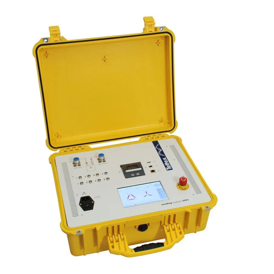
Page 34: Front Panel
Connector for HV cable “H” connection, Red (to High voltage side of DUT) I/O connector (for cascading of additional temperature interfaces) Tap Changer connector (for optional Tap Changer Remote interface TAP/2293 ) 6 Temperature probes connectors Power inlet with integrated mains switch and fuse holder... - Page 35 The third green LED on the bottom indicates a safe state. 15 Additional PE (Protective Earth) connector. (Parallel to the PE pin of the power inlet connector) Can be used when power inlet cable is not connected to Earth. Front Panel...
-
Page 36: Connection And Setup
Connection and Setup Connection Cables The equipment is delivered with 8 measuring cables and two adaptors as standard scope of supply. Cable set for the Low Voltage side X ( black clamps)”. Cables are equipped with special Kelvin clamps. Cable set for the High Voltage side H (red clamps)”. Cables are equipped with special Kelvin clamps. -
Page 37: Cable Extensions (Optional)
Adaptor for the low volt side (black ring in the connector) Adaptor for the high volt side (red ring in the connector) Colour code has been defined in the cables and must be followed to guarantee the proper device connection. Red is used for the connections to the DUT’s High Voltage side “H”, Black is used for the connections to the DUT’s Low voltage side “L”. -
Page 38: Connection Without Extenders
Red connector has to be connected to the right side (2) defined by a red dot. (H) Black connector has to be connected to the left side (1) defined by a black dot. (X) 5.2.1 Connection without extenders Connect the adaptors to the device connectors. The easiest way to screw the connector is to hold them straight with one hand and screw with the other one. -
Page 39: Connection In Automated Mode To A 3 Phase Transformer
If a DUT type is entered in the top bar of the display, the unit shows an icon of the DUT type and on each connection the label of the correct cable to be connected is displayed. 5.2.3 Connection in Automated mode to a 3 phase transformer For a normal transformer, connection is done following the labels in the cable;... -
Page 40: Connection In Automated Mode To A 1 Phase Transformer
5.2.4 Connection in Automated mode to a 1 phase transformer For a normal transformer, connection is done following the labels in the cable; means connecting transformer phases with corresponding labeled cables as shown in the bellow diagram. Connection and Setup... -
Page 41: Connection In Classic Mode
5.2.5 Connection in Classic mode To connect the device to a test object different from a transformer, connections must be done as following. 1 Resistance Terminal A positive of the high current power supply Terminal N negative of the high current power supply ... -
Page 42: Usb Type A Host Port
Terminal B positive of first voltage measurement Terminal C negative of first voltage measurement Terminal b positive of the second voltage measurement Terminal c negative of the second voltage measurement USB Type A Host Port The USB Type A Host Port support various devices: - USB Flash Memory Stick (for Data Export) - Keyboard - Mouse... - Page 43 In case of frequent usage of the USB A port (typically for Data Export to a USB Flash Memory Stick), we strongly recommend using a short extension cable to protect the front panel connector of the device. See the following picture as an example: Connection and Setup...
-
Page 44: User Interface
User Interface Startup To start the device, turn on the main switch and wait until the warning screen arises. Booting can take some seconds. Read carefully the warning messages and click OK when understood. Read also carefully the safety warnings at the beginning of this manual before operating the instrument. User Interface... -
Page 45: Structure
Structure The device is equipped with an intuitive interface, and all parameters are selected through its touch screen. Use the finger or a non sharp object to operate the touch screen. Using sharp or metallic pointers can damage the screen! The interface of the application software consists of four designated areas: Test &... -
Page 46: Selection Of Dut Type
Phase displacement HV / TV 6.3.1 Selection of DUT Type Transformer main parameters selection is done in the upper part of the main screen. The HV winding configuration, the LV winding configuration and the phase shift can easily be selected in the pop up menu. -
Page 47: Dut Data Definition
Example for a setup of a single phase transformer with no phase shift Example for a setup of a single phase auto transformer Example for a setup of a wye 3 phase auto transformer The selected transformer is then shown on a graphical mode in the main screen. In case tertiary winding has been selected two arrows in the right side will indicate that a tertiary winding has been configured. - Page 48 Specification Here the definition about Nominal Voltages of windings have to be entered (used for desired value of ratios and as limits) If a winding is equipped with a Tap Changer (on load or off load) it has to be configured by clicking the selection box in the left of the corresponding winding (HV for High voltage, LV for low voltage and TV for tertiary winding).
-
Page 49: Tap Changer Configuration
6.3.3 Tap Changer configuration In case the transformer is equipped with a tap changer, it can be easily configured in the device to allow automation of the measuring procedure and complete test reports generation. The tap changer configuration screen is accessed selecting the DUT configuration button in the upper DUT Top Bar, and selecting the specific folder. - Page 50 Total number of tap changer Actu positions al tap First position chan number confi Select if if when gurati more than 1 nominal position, the numbers are consecutive Select if the Number of intermediate nominal taps are positions reachable and can be measured Enter each theoretical tap voltage in...
- Page 51 bottom & option will automatically populate voltage values when apply is pressed. In this example, the bottom tap is 11kV and the top tap is 18kV. The apply button calculates each voltage proportion to the number of taps. Nominal Tap Nominal tap is indicated by the symbol “<<>>”...
-
Page 52: Test Name
6.3.3.2 Tap changer configuration examples Example 1 9 taps transformer, with 3 reachable intermediate taps with no continuous naming, button position number 1 and nominal tap 4 Example 2 9 taps transformer, with button position number 10, 1 nominal tap in position 14. 6.3.4 Test Name The first line shows the name of actual test. -
Page 53: Active Window
Active Window In the centre of the display graphical information and measuring status of the current application is shown. The screen change depending of the operating mode or the application selected. Automated mode main screen Classic mode main screen Demagnetization screen Function Keys (Bottom Bar) At the bottom of the window a key bar is located which includes all buttons necessary to perform measurements, prepare setups or analyze test results. -
Page 54: Device Information
Device Information The device information is accessible over Setup button in the bottom bar of each application. Select the “Miscellaneous” folder. Here you will find the system info. The device information is accessible over Setup button in the bottom bar of each application. -
Page 55: Printing Results
Open a new test based in the actual data Load a recorded test Save actual test under the actual name Save actual test under a new name Delete actual test Export data to a memory stick Print the actual test in the included printer 6.8.2 Printing results. - Page 56 Select if the device under test data (DUT) and the setup data want to be exported to the memory stick Select the measurements that wants to be exported, resistance, cooling curve and demagnetization. Select the CSV output file destination: USB Stick - Writes the report to the attached USB Memory Stick Int.
-
Page 57: Webserver Access / Ethernet Interface
6.8.4 Webserver access / Ethernet interface To access the files that have been written to the internal webserver storage, a network connection between the device and your office computer must be established. Please refer to the “Remote Control” section of this manual for further help. You can find the IP address configuration of your device in the “Setup”... -
Page 58: Resistance Measurement
Resistance Measurement Operating modes The unit can perform resistance on all types of objects, but has been specially designed to measure resistance on highly inductive objects (as for example transformer’s windings, generators windings, etc). During resistance measurement the device can be used in two operating modes: the “classic mode”... - Page 59 Automatic mode selection is selected in the measurement folder, clicking in the function key bar. When selected, additional options like YnD measurement and tap sequence are available Resistance Measurement...
-
Page 60: Function Keys During Resistance In Automated Mode
7.2.2 Function keys during resistance in automated mode While in automated resistance measurement mode, following actions are available in the button key. The buttons are case sensitive, i.e. they change according to the actual status. Start the measurement Record a result while manual recording mode is used Stop the measurement Deselect all windings Select all windings... -
Page 61: Performing A Test Using Automated Mode
Status bar (actual procedure step, Temp etc) timer, eratu Safe Statu State s with indicator Selected current with SC Active windings to measure with SC Tap changer setting with SC * SC = Shortcut; direct action or access to setup over touching Tap Changer Visualization: Tap changer graphical representation “Remote Controlled”... -
Page 62: Set Up Dut Data
DUT general data Configuration of the automatic Selection of the temperature corresponding DUT correction main parameters Selection of the desired test current Configuration of the tap changer (when existing) Auto recording selection Winding material selection Measuring Exporting and printing results 7.3.2 Set up DUT data To set up the steps with DUT related data: ... -
Page 63: Test Current Recommendations
The measuring current must be introduce independent for each winding and is done in the “measurement” folder clicking over the Setup button in the function key bar. A shortcut for current selection is available in the main screen; clicking in the current by winding drawing 7.3.4 Test current recommendations Normally 32 Amps are not necessary, except when really low resistances (<0.5mOhm) have to be... -
Page 64: Auto Recording Configuration
If the transformer is equipped with tap changer and it has been configured in the device, the tap changer measuring sequence should be defined. Different options are available in the Tap Control folder, selecting the setup in the main menu. Measurement will be done tap by tap (no sequence to be followed), the tap to be measured can be manually selected in the main screen. -
Page 65: Tap Control
Value is stable and therefore recorded when a change of 0.0003% per second, or 0.003% per 10 seconds or 0.03% per 100 seconds is achieved. Value is stable and therefore recorded when a change of 0.003% per second, or 0.03% per 10 seconds or 0.3% per 100 seconds is achieved. User can manually introduce any stabilization parameter, the value introduced is the slope of the change, and is defined as value (in percentage) per second 7.3.7 Tap Control... -
Page 66: Temperature Correction
See also chapter “Tap Changer Interface” for more details and connection advice. 7.3.8 Temperature correction The instrument can perform temperature correction for the values measured, as related in the IEC or other national or international standard. Select the winding material Reference temperature selection Test object actual... - Page 67 Before starting the test, a screen showing the tap position that will be measured arises. Tap changer must be positioned in this position. Measurement sequence depends on the tap changer configuration menu. Tap changer position selection (automatic with optional tap changer remote control) Charging the transformer Resistance measurement ( all...
- Page 68 All phases will be measured Only HV side will be measured Only phase AC in the HV winding will be measured Measurements will be automatically saved after each test. Data storage options can be selected in the Data folder, clicking in the setup button of the function key bar. Overwrite ...
-
Page 69: Classic Mode
Classic mode 7.4.1 Generalities On classic mode, the unit work as a standard low resistance measuring bridge using the Kelvin method. The unit includes one current power supply and 2 voltage measuring channels (for measuring up to 2 resistances simultaneously), This mode can be used for measuring test objects different from transformers, as well as for calibration purposes. -
Page 70: Active Window
Open data handling functions 7.4.3 Active window Temperature correction, when active the reference temperature is shown. Measuring circuit schematic, letters indicate the cable labels to be used Label and value of the resistance Test current selected Test object status. Be advised that the external red lamp is the safety master (14 in the front panel description). -
Page 71: Performing A Test Using Classic Mode
Performing a test using Classic mode Before operating the instrument, make sure that the safety rules have been fully read and understood. It is the responsibility of the end user to ensure that the system is operated in a safe manner. Performing a resistance measurement using classic mode consist of following steps DUT general data Selection of the... -
Page 72: Test Current Selection
Select the winding material Reference temperature selection Test object actual temperature If automatic temperature correction is desired, the DUT actual temperature and the reference temperature have to be introduced by selecting the temperature folder after clicking the setup button in the function key bar. Read the chapter “Temperature correction”... -
Page 73: Auto Recoding Configuration
7.5.5 Auto recoding configuration Measurement can be done in auto stop mode (value is automatically recorded when stable) or in manual mode (unit stays measuring until the operator click the stop button), selection between both operations modes is done in the setup screen, Data folder. - Page 74 Charging Resistance measurement Discharging Measurement results Click start button to initiate measurement running Measurement results the test If auto recording is active, instrument will record the value and stop the measurement when the stabilization condition has been reached. Otherwise the stop button has to be pushed to stop the test.
- Page 75 Results can also be shown as a table list, selecting the list button in the function key bar. Resistance Measurement...
-
Page 76: Temperature Measurement
Temperature Measurement Temperature sensors can be connected to the corresponding connectors in the front panel. If more than 6 temperature sensors are requested, optional extender can be purchased. PT100 sensors are used for temperature measurement. Sensors for liquids or magnetic sensors are available, consult the accessories chapter for additional information. - Page 77 Actual reading of the six temperature channels. To be added to the medium temperature they should be selected. A description (text) can be added to every temperature channel. By clicking on a sensor line in this list you enter the temperature probe definition dialog: Select the position where the sensor is mounted on the DUT by clicking.
-
Page 78: Demagnetization
But this method requires a very large and not portable controllable AC voltage source. With the 2293 demagnetization function, the hysteresis loop of the transformer is calculated using a special algorithm, later using an iterative procedure running in several cycles the... -
Page 79: User Interface
User interface The demagnetization procedure is done automatically. Few parameters have to be selected before proceeding to demagnetize the transformer. Parameters selection and function are accessible in the demagnetization function. To access to this application, select demagnetize function in the applications bar (side bar) 8.2.1 Active Window The demagnetization function main screen components are described below. -
Page 80: Performing A Demagnetization
Change display to graphic mode Open setup menu for the selected measuring application Performing a demagnetization 8.3.1 Measurement steps Performing demagnetization with the 2293, consist of following steps Phase selection and Parameters definition Demagnetizing Export and printing results Before operating the instrument, make sure that the safety rules have been fully read and understood. - Page 81 Injection Phase and Winding Selection of winding and phases to be used for the demagnetization. It is recommended to use the high voltage side and the center limb of the transformer. Current used during the demagnetization. It is recommended to use at least 2 times the no load losses current of the transformer of the winding used Stop criteria to determine when a demagnetisation run will be completed: Cycles...
-
Page 82: Demagnetizing
8.3.3 Demagnetizing Click the start button and the instrument will perform the demagnetization. Current injection and resistance Transformer is being Transformer demagnetized measurement demagnetized. The bar indicates the actual core flux. Application hints Repeating the demagnetization function more than once does theoretically not result in a much better demagnetization of the transformer because the procedure starts with a maximal magnetisation to get a defined initial condition of the core. -
Page 83: Heat Run - Cooling Curve
Heat Run – Cooling Curve Theory The purpose of this test is to establish the top oil temperature rise in steady-state condition with dissipation of total losses and to establish the average winding temperature rise at rated current and with the top oil temperature rise specified before. This target is achieved in two main steps: First the top oil and average oil temperature rises are established when the transformer is subjected to a test voltage such that the measured active power is equal to the total losses of the... -
Page 84: User Interface
User interface The 2293 is equipped with a heat run function which allows the measurement of the resistance values for the cooling curve calculation during heat run test. To access to this feature, select cooling curve function in the applications bar (side bar). - Page 85 Stops the resistance measurement but NOT the timer (with “Start Meas” the measurement can be reactivated) In case the test is stopped by this button during first stage (t2-t4) of 3 phase sequential measurement, the whole sequence will be redo after reactivated. Stop and resets the application (resistance measurement and timer) Move tap changer, that marked with , one step down...
-
Page 86: Performing A Resistance Measurement (Cooling Curve)
Performing a resistance measurement (cooling curve) Measurement steps Performing resistance measurement on cooling curve test with the 2293, consist of following steps Measuring phases and windings selection Measuring Parameters Measuring values definition recording interval Starting the timer Measuring Parameters definition... -
Page 87: Test Current Selection
The recording option is available after selecting the Setup button in the function key bar while cooling curve is selected in the applications bar. When Single Phase is selected, the measurement will be performed on one phase of each selected winding. The interval (time between readings) and the number of readings can be here selected by clicking in the corresponding field... -
Page 88: Temperature Settings
9.3.4 Temperature settings The temperature measuring screen is accessed clicking the Setup button, under the temperature folder in the function key bar. Activate the used probes by clicking the left sided check box. Click on the single probes line to enter the configuration dialog of the single probes (position &... -
Page 89: Measurement Single Phase
9.3.6 Measurement Single Phase Measurement consist on two steps, initiate the timer when the power supply is disconnected, and then, after connecting the instrument by clicking the start button. Start the timer when power supply When instrument connected, click All measurement points recorded, is disconnected by clicking Start Start Meas, a reading is stored measurement finalized, last... -
Page 90: Export Results
To see the measured results in graph format, select the Curve in the function key bar. Measured results are shown in graph mode by selecting the curve button. If additional tests of other phases, windings or taps are performed, the graph shows the results for the last 9 windings measured. -
Page 91: Heat Run - Temperature Rise
10 Heat Run - Temperature Rise 10.1 Overview The 2293 is equipped with an optional temperature rise function. This optional feature is enabled using the license manager. This process only needs to be completed the first time temperature rise is used. - Page 92 Enter the license key in the Temp. Rise box and press OK. If the temperature rise function was previously used with a trial license key, clear this number and replace it with the full license key. Press Yes to reboot the unit and install the detection function.
-
Page 93: Active Window
10.2.1 Active Window The temperature rise function main screen components are described below. 10.2.2 Function keys While in temperature rise application, following actions are available in the button key bar. The buttons are case sensitive, i.e. they change according to the actual status. Start the temperature rise Resume the temperature rise Stop the temperature rise... -
Page 94: Performing A Temperature Rise Test
10.3 Performing a Temperature Rise Test 10.3.1 Measurement Steps Performing temperature rise test with the 2293, consist of following steps Measuring parameters definition Liquid cooled or dry type transformer? Temperature probe setup Liquid cooled Apply total loss injection Apply rated current... -
Page 95: Recording Settings
10.3.2 Recording Settings The temperature rise settings screen is accessed by clicking the Setup button in the function key bar when temperature rise is selected in the application bar. The interval (time between readings) can be selected by clicking in this field. Consider the predicted duration of the test when choosing a value because the test is limited to a maximum of 500 readings per data set. -
Page 96: Temperature Settings
Liquid cooled transformers default to stability check on Oil Top. Dry type transformers default to stability check on winding and core. Dry type transformer setup is only for the heating part of the test. There is no step 2, rated current injection. -
Page 97: Liquid Cooled Transformer Measurement
With these arrows you can toggle trough the single probes definitions without closing this dialog window. The temperature settings are common for the Temperature Rise and Cooling Curve functions Liquid cooled transformers will use the ambient, oil, rad. top and rad. Bottom positions. - Page 98 Temperature measurements When the countdown is complete, Click Continue to switch automatic continue while the phase 2 timer click OK from Temperature Rise to Cooling counts down. Curve application. When the rated current injection is switched off, press Start Timer. Then connect immediately the measurement clamps to the transformer and press Start Meas...
-
Page 99: Dry Type Transformer Measurement
10.3.5 Dry Type Transformer Measurement Measurement consists of only two steps. Firstly start the test when HV is applied to the transformer. Second continue to the cooling curve application before the HV supply is switched off. Click Start for temperature A warning message is displayed The latest readings are shown on recording to begin when HV... -
Page 100: View Results
10.3.6 View Results To see the measured results, select the List in the function key bar. Measured results are shown in a table mode by selecting the list button. The results shown are dependent on whether the transformer is liquid cooled or dry type and the sensor positions used during the test. -
Page 101: Transformer Configuration Detection
11.2 User Interface The 2293 is equipped with an optional detection function. This optional feature is enabled using the license manager. This process only needs to be completed the first time detection is used. To access to the license manager, select... - Page 102 Select the Miscellaneous folder and then press the License Manager button. Enter the license key in the V. G. Detection box and press OK. If the detection function was previously used with a trial license key, clear this number and replace it with the full license key.
- Page 103 You may need to press the up/down arrow buttons to view the detection button depending on which other functions are enabled. Trial licenses for detection are available which permit a limited number of tests to be performed. The remaining number of tests is displayed on the license screen.
-
Page 104: Active Window
11.2.1 Active Window The detection function main screen components are described below. 11.2.2 Function keys While in detection application, following actions are available in the button key bar. The buttons are case sensitive, i.e. they change according to the actual status. Start the detection Stop the detection Move tap changer, that marked with... -
Page 105: Performing A Detection
11.3 Performing a Detection 11.3.1 Measurement steps Performing vector group detection with the 2293, consist of following steps Parameters definition Detection Export and printing results Before operating the instrument, make sure that the safety rules have been fully read and understood. It is the responsibility of the end user to ensure that the system is operated in a safe manner. - Page 106 Click the start button and instrument will perform the vector group detection. Voltage applied and detection Phase angle measurements are Neutral measurements are measurements are running. The completed. The grid shows a completed. The grid shows the grid shows all transformer reduced set of possible likely transformer configuration in configurations are possible.
-
Page 107: Export Results
After detecting HV/TV, pressing the green or yellow squares will set the HV/TV configuration in the DUT details (top bar). 11.3.4 Export results See chapter “Data Handling” for information about exporting and printing results. Transformer configuration Detection... -
Page 108: Turns Ratio Measurement
12 Turns Ratio Measurement 12.1 Overview The unit can perform ratio measurements on all types of objects, but has been specially designed to measure ratios on highly inductive objects (as for example transformer’s windings, generators windings, etc). This optional feature is enabled using the license manager. This process only needs to be completed the first time magnetic balance is used. -
Page 109: Measurement Example
In the first example the DUT (YNd11 with turn fault on phase C) is measured as YNd11. Because the neutral is available, the 2293 can directly measure each individual phase. The system steps through the following procedure: Connect to the DUT according the “Connection”... - Page 110 In the second example same the DUT as in the first example (YNd11 with turn fault on phase C) is measured as Yd11. Because the neutral is not available, the 2293 can not measure each phase individually. The measurement returns a combination of ratios of all three phases. The system steps through the following procedure: Connect to the DUT according the “Connection”...
- Page 111 When looking at the measurement sections ("Ratio Raw" and "Ratio Turns") of these two examples, we can clearly see a difference. If measuring without neutral (e.g. Y or Z) a deviation in only one Phase inflicts all three measurements. The deviations are -8.94%, -8.99% and -28.3% although there is a turn fault in only one phase.
-
Page 112: Tables
12.2.3 Tables This table describes the method used to measure a certain transformer configuration. ZN is always handled the same way as Z. For simplicity the connection table is valid for a 0 or 1 clock number. For other clock numbers the connections are rotated/inversed accordingly. VR:TR Factor applied from Ratio Raw to Ratio Voltage TR:VR... - Page 113 VR:RR TR:VR TR Method True TR Con HV Con LV System H1-H2H3 X1-X2 H2-H3H1 X2-X3 1.00000 1.00000 Equations H3-H1H2 X3-X1 System H1-H2H3 X1-X2 H2-H3H1 X2-X3 1.00000 1.00000 Equations H3-H1H2 X3-X1 System H1-H2H3 X1-X2 1/√3 2/√3 H2-H3H1 X2-X3 0.57735 1.15470 Equations H3-H1H2 X3-X1 H1-H2H3...
- Page 114 VR:RR TR:VR TR Method True TR Con HV Con LV System H1-H2H3 X1-X2 1/√3 2/√3 H2-H3H1 X2-X3 0.57735 1.15470 Equations H3-H1H2 X3-X1 H1-H2 X0-X2 1/√3 √3 Directly H2-H3 X0-X3 0.57735 1.73205 measured H3-H1 X0-X1 H1-H2 X1-X2 Directly H2-H3 X2-X3 1.00000 1.00000 measured H3-H1...
-
Page 115: User Interface
12.3 User Interface To access the turns ratio feature, select turns ratio function in the applications bar (side bar). You may need to press the up/down arrow buttons to view the turns ratio button depending on which other functions are enabled. 12.3.1 Function keys While in turns ratio application, following actions are available in the button key bar. -
Page 116: Active Window
12.3.2 Active Window The turns ratio measurement screen is below described: * SC = Shortcut; direct action or access to setup over touching Tap Changer Visualization: Tap changer graphical representation “Remote Controlled” is active in dialog “Setup” this winding is selected at “Tap Control” / “Winding” in dialog “Setup” tap-changer is defined as “On Load”... -
Page 117: Set Up Dut Data
DUT general data Configuration of Selection of the displayed results corresponding DUT main parameters Selection of the desired test voltage Configuration of the tap changer (when existing) Measuring mode selection Configuration of the nominal and tap voltages Measuring Exporting and printing results Before operating the instrument, make sure that the safety rules have been fully read and understood. -
Page 118: Turns Ratio Measurement On Current Instrument Transformers
12.4.3 Turns ratio measurement on Current instrument transformers Care has to be taken to ensure that the current transformer is connected correctly otherwise there is a risk of damage to the CT and Instrument. There is also the risk of injury. - Page 119 If the CT has multiple taps, these must be tested individually. Each tap on the secondary is tested in turn, by connecting the “H” connections to each tap in turn. How this is handled depends on whether the current transformer provides a single winding with multiple taps, or separate secondary windings.
-
Page 120: Data Handling Definitions
12.4.4 Data handling definitions Storage: Overwrite when a measurement is repeated, results overwrite the actual measured values for the tap Append When a measurement is repeated, results are added in the list but previous results are also kept. Printout: The printout option controls whether the default paper printout shows turns ratios or... -
Page 121: Test Voltage Selection
12.4.5 Test Voltage Selection Selection of the measuring voltage is done by clicking on the test voltage field in the main screen, any value between 0 and 67V can be introduced, some values are directly selectable. 12.4.6 Test frequency selection Selection of the measuring frequency is done automatically by the unit. -
Page 122: Measuring Mode Selection
12.4.8 Measuring mode selection The turns ratio function has two measuring modes: Classic mode (Fast): This is the standard method for determining the Transformer Turns Ratio. It performs a single measurement per Phase by applying sinusoidal AC Voltage (up to 67V RMS) to the High Voltage side of the transformer. - Page 123 Before starting the test, a screen showing the tap position that will be measured arises. Tap changer must be positioned in this position. Measurement sequence depends on the tap changer configuration menu. Tap changer position selection (automatic with optional tap changer remote control) Charging the transformer...
- Page 124 If manual recording is active, the instrument will repeatedly measure a phase. Pressing the record button stores the latest result and moves to the next phase. Connection shows the energisation, measurement and shorting connections used in the test Ratio raw shows the measured voltage ratio using the connections Ratio volt shows the actual voltage ratio of the transformer taking into account the measurement...
- Page 125 Phase shows the phase shift between the energisation and measurement connections. Current shows the primary excitation current during the measurement. The white box shows the measured turns ratio and the turns ratio deviation between the measured result and the theoretical value. Ratio results which exceed the ratio threshold value are highlighted in red.
- Page 126 Overwrite when a measurement is repeated, results overwrite the actual measured values Append When a measurement is repeated, results are added in the list but previous results are also kept. Results can also be shown as a table list, selecting the list button in the function key bar.
-
Page 127: Exporting And Printing Results
Clicking the phase column changes the report to show decimal or degrees/minutes 12.4.10 Exporting and printing results See the chapter “Data Handling” for information about exporting and printing results. Turns Ratio Measurement... -
Page 128: Arbitrary Phase
In the 2293 arbitrary phase shift measurement is achieved by using a single-phase supply with no extra hardware. The necessary three phase equivalent voltages at different transformer terminals are simulated by energizing a pair of the transformer terminals and interconnecting certain other terminals. - Page 129 Enter the license key in the “Arbitrary Phase” box and press OK. If the arbitrary phase function was previously used with a trial license key, clear this number and replace it with the full license key. A turns ratio license must be present for the arbitrary function to be active.
-
Page 130: User Interface
12.7 User Interface 12.7.1 Setup To access the arbitrary phase feature, select turns ratio function in the applications bar (side bar). Set the DUT winding types. Select in the phase displacement drop down list the closest clock number and also activate there the “Arbitrary” button in the lowest position. The arbitrary measuring mode is activated now. -
Page 131: Measuring
When the unconventional transformer is selected the measurement screen displayed is described below. No transformer windings are shown due to the unconventional nature of the device. An example usage would be a quad-booster transformer. 12.7.4 Measuring Performing an arbitrary phase measurement on a transformer is similar to a turns ratio measurement. - Page 132 Click start button to initiate the Automatic measurement running Measurement results test Connection shows the energisation, measurement and shorting connections used in the test Ratio raw shows the measured voltage ratio using the connections Ratio volt shows the actual voltage ratio of the transformer taking into account the measurement connections and the configuration of the transformer.
- Page 133 Phase shows the phase shift between the energisation and measurement connections. Current shows -,--. The primary excitation current during the measurement is not shown because several different single phase measurements are taken for each connection and used to calculate the voltage ratio and phase angle. Ratio results which exceed the ratio threshold value are highlighted in red.
- Page 134 The test procedure for an unconventional transformer is similar but the red highlights are not shown because the winding arrangement is unknown. Turns Ratio Measurement...
-
Page 135: Magnetic Balance
13.3 Activate the Magnetic Balance option The 2293 is equipped with an optional magnetic balance function. This optional feature is enabled using the license manager. This process only needs to be completed the first time magnetic balance is used. - Page 136 To access to the license manager, select setup function key in the bottom bar of any application Select the Miscellaneous folder and then press the License Manager button. Enter the license key in the Mag. Balance box and press OK. If the magnetic balance function was previously used with a trial license key, clear this number and replace it with the...
-
Page 137: User Interface
Trial licenses for magnetic balance are available which permit a limited number of tests to be performed. The remaining number of tests is displayed on the license screen. Removing the trial license key will remove the magnetic balance function from the application bar. 13.4 User Interface To access the magnetic balance feature, select... -
Page 138: Active Window
Change display to graphic mode Open setup menu for the selected measuring application 13.4.2 Active Window The magnetic balance measurement screen is described below: * SC = Shortcut; direct action or access to setup over touching Tap Changer Visualization: Tap changer graphical representation “Remote Controlled”... -
Page 139: Measurement
13.5 Measurement 13.5.1 Measurement steps Performing a magnetic balance measurement on a transformer consist of following steps DUT general data Configuration of Selection of the displayed results corresponding DUT main parameters Selection of the desired test voltage Configuration of the tap changer (when existing) Measuring mode selection... -
Page 140: Data Handling Definitions
13.5.3 Data handling definitions Storage: Overwrite when a measurement is repeated, results overwrite the actual measured values for the tap Append When a measurement is repeated, results are added in the list but previous results are also kept. Recording: Measurement can be done in auto stop mode (value is automatically recorded when stable) -
Page 141: Test Frequency Selection
13.5.5 Test frequency selection Selection of the measuring frequency is done automatically by the unit. Just select if your DUT is a 50/60Hz type or a 16.7Hz traction transformer type. 13.5.6 Magnetic Imbalance selection Imbalance: The imbalance threshold is the allowed percentage difference between the voltages measured on transformer limbs which should... -
Page 142: Measuring
Shortcut to DUT setup. Similar to pressing on main screen 13.5.8 Measuring Performing a measurement on a transformer is quite simple. Once all transformer and options have been introduced; just click the start button. The instrument will perform all operations automatically. - Page 143 Connection shows the energisation and measurement connections used in the test. Each limb of the transformer is sequentially energised and then the other limb voltages are measured. Highlighted area shows the voltage of the energized limb and the voltage measured on the other limbs. The energisation current for each limb of the transformer is shown.
-
Page 144: Exporting And Printing Results
Overwrite when a measurement is repeated, results overwrite the actual measured values Append When a measurement is repeated, results are added in the list but previous results are also kept. Results can also be shown as a table list, selecting the list button in the function key bar. -
Page 145: Application Hints
13.6 Application hints 13.6.1 Core Magnetization Magnetic Balance results are sensitive to Transformer Core Magnetization. To get reproducible results, make sure to properly demagnetize the transformer core (directly) before performing a magnetic balance test: In a lot of cases, the built-in demagnetization function of the WA2293 will deliver good result. In some cases, especially for larger power transformer (>50MVA), it can be necessary to use a High Voltage AC power supply to properly demagnetize the transformer. - Page 146 Magnetic Balance...
-
Page 147: Short Circuit Impedance
14 Short circuit impedance 14.1 Overview The unit can perform the short circuit impedance test of a transformer at reduced voltages, the short circuit impedance in a transformer is quite linear with the voltage and therefore an extrapolation to the nominal voltage can be perform for comparison. This optional feature is enabled using the license manager. -
Page 148: User Interface
line to line voltage in V from nameplate or three phases transformers, test can be done by measuring each phase separately (phase to phase ) and then calculating the transformer impedance according below formula Where: = Short circuit impedance phase a to b = Short circuit impedance phase a to c... -
Page 149: Active Window
Move tap changer one step down Move tap changer one step up Change display to list mode Change display to graphic mode Open setup menu for the selected measuring application 14.3.2 Active window * Shortcut; direct action or access to setup over touching: 14.4 Measurement 14.4.1 Measurement procedure Performing a turns ratio measurement on a transformer consist of following steps... -
Page 150: Transformer Connection
DUT LV side external short circuit (use a proper connection) Configuration of displayed results DUT general data Selection of the desired test Main parameters introduction voltage and current (Group connection) Configuration of the tap changer Measuring mode selection (when existing) Configuration of the voltages and Click start ->... -
Page 151: Set Up Dut Data
14.4.3 Set up DUT data To set up the steps with DUT related data: see related chapters in the “User Interface” part. The Magnetic Balance function is mostly applicable to start with Neutral Windings. On these configurations unbalance results can be a result of a transformer fault or residual magnetism, 14.4.4 Measurement Settings To access the measuring parameters, click setup button in the bottom of the screen, and then... - Page 152 The test Voltage, maximum current and frequency can be selected By clicking in the Voltage text Box, a window pop up proposing several voltages. To select one just click with the mouse over the desired value By clicking the current Box, a window will pop up proposing several maximum currents, an error message will arise during the test if the selected maximum current is exceeded...
-
Page 153: Data Handling
User can also introduce manually any desired value between the limits by clicking the “User Defined” Text Box. A Window to introduce the desired voltage manually will pop up, just introduce the value and click “OK” button. 14.4.5 Data Handling To access the data parameters, click setup button in the bottom of the screen, and then select “Data”... -
Page 154: Measuring
14.4.8 Measuring Performing a measurement on a transformer is quite simple. Once all transformer and options have been introduced; just click the start button. The instrument will perform all operations automatically. Before a test can be done, the tap position has to be selected. Click start button to initiate the Automatic measurement running Measurement results... -
Page 155: Exporting And Printing Results
Connection Clamps used during the test Short Short circuited winding Voltage Voltage applied during the measurement Current Current applied during the measurement Frequency Frequency applied during the measurement Impedance Single phase impedance measured (Phase Voltage/ Phase Current) Single phase short circuit impedance calculation Short circuit Imp ( After all phases are completed, then a calculation of the transformer overall values is done based in the single phase measurements... -
Page 156: Dynamic Resistance On Tap Changer
15 Dynamic resistance on tap changer 15.1 Overview The unit can perform optionally the Dynamic resistance measurement a transformer. This optional feature is enabled using the license manager. This process only needs to be completed the first time Dynamic Resistance (Tap changer) feature is used. For instruction how to enable a feature please read Chapter 16 Optional Features activation. -
Page 157: Dynamic Resistance Test
The tap change operation consist of 3 steps The next tap is preselected by the tap selector at no load (no current circulation). The arcing switch (on load tap changer) transfer the load current from the tap in operation to the preselected tap trough following operations Switch TS2 close, current from tap selector 1 circulates trough TS1. - Page 158 Following parameters are calculated and recorded by the device for each tap change. tFall [mS]: Time from the staring of the tap changer movement (drop in current) until the minimum current is reached tRise [mS]: Time from minimum current reached until current becomes stable Delta: Current drop from stabilization to the minimum while changing tap Dynamic resistance on tap...
-
Page 159: User Interface
15.3 User Interface To access to the Tap changer (dynamic resistance) feature, select Tap changer function in the applications bar (side bar). You may need to press the up/down arrow buttons to view the magnetic balance button depending on which other functions are enabled. -
Page 160: Active Window
Open setup menu for the selected measuring application 15.3.2 Active window Active Window can be changed between Single test, All test and List by clicking the respective button in the bottom bar.. Click “All ” button to change Click “List” to change Click “Single”... - Page 161 Active Window List Dynamic resistance on tap changer...
-
Page 162: Measurement
15.4 Measurement 15.4.1 Measurement procedure A tap changer test consist of following steps. Dynamic resistance on tap changer... -
Page 163: Transformer Connection
DUT general data Main parameters introduction Tap changer test Select phases to be measured (Group connection) Tap changer test On load Tap changer configuration Select Taps to be measured Tap changer Test current selection Select the number of cleaning cycles (if necessary) Tap changer test Select tap changer operation Static... - Page 164 Short circuit done by the device (recommended and selected by default). The device will short circuit the secondary side of the transformer. This feature will allow a faster magnetization of the transformer for the first resistance reading Short circuit done externally (not recommended). In case last test done was Short circuit impedance and short circuit is already available.
-
Page 165: Set Up Dut Data
15.4.3 Set up DUT data To set up the steps with DUT related data: see related chapters in the “User Interface” part. 15.4.4 Measurement Settings To access the measuring parameters, click setup button in the bottom of the screen, and then select “Measurement”... -
Page 166: Static Resistance Settings
By clicking the current Box, a window will pop up proposing several maximum currents. The maximum selectable current for this test is 12A. Any value can also be introduced by clicking over the “user defined values” textbox. Two connections modes can be selected by how the sort circuit is done in the not measured transformer winding. -
Page 167: Dynamic Resistance Settings
The resistance can be recorded automatically (when the stabilization criteria beside is fulfilled) or manually by operator by clicking the record button when required. Stabilization criteria can be defined, high accurate , Fast or user defined. 15.4.6 Dynamic resistance settings To access the Dynamic resistance settings, click setup button in the bottom of the screen, and then select “Dynamic”... - Page 168 Taps to be measured, by clicking the textbox with the tap number the tap position can be selected Testing order direction. Recording will be done when: Up -> Only when increasing the tap Down -> only when decreasing the tap Both ->...
-
Page 169: Temperature Settings
15.4.7 Temperature settings For temperature settings, refer to chapter 7.6 Temperature Measurement 15.4.8 Miscellaneous For information about the tap control window, refers to Chapter 6.7 Device Information 15.4.9 Measuring The measurement procedure will slightly differ if the remote tap changer accessory is available and connected to the transformer or not. -
Page 170: Measurement Results
The triggering of the measurement is automatically done by the instrument, no configuration or particular settings are needed for this purpose. The following steps are performed while measuring the tap changer. Steps 3 to 5 will be repeated for all taps selected in the settings. Step 6 is only necessary if the tap changer accessory is not available. -
Page 171: Exporting And Printing
tRise [mS]: Time from minimum current reached until current becomes stable Delta: Current drop from stabilization to the minimum while changing tap For explanation about these parameters, see 15.2.2 Dynamic resistance test The above parameters should be similar for all taps, deviations between one tap and the others are an indication of tap changer problem. -
Page 172: Optional Features Activation
16 Optional Features activation 16.1 Software key Activation Optional features are enabled using the license manager. This process only needs to be completed the first time the feature is used. To access to the license manager, select setup function key in the bottom bar of any application Select the Miscellaneous folder and then press the License Manager button. - Page 173 Enter the license key in the corresponding row If the feature was previously used with a trial license key, clear this number and replace it with the full license key. Press Yes to reboot the unit and install the function. The Magnetic Balance function is mostly applicable to start with Neutral Windings.
-
Page 174: Tap Changer Interface
Tap changer interface allows the remote control of a motorized tap changer, as well as the remote control of the 2293 when operator is placed in front of the tap changer and far away from the device. The tap changer remote controller consist of an... -
Page 175: Tap Changer Feedback Signal
2293 supplies a 3.3V signal, and wait for the returning signal as confirmation that operation is finished. Feedback (sense input) -
Page 176: Temperature Interfaces
18 Temperature Interfaces 18.1 General Notes The 2293 unit supports 6 internal and max. 24 external PT100 Class A sensors. Sensors for magnetic surface (a) or for liquids (b) are available. See also chapter “Accessories”. By a wrong probe handling or a not proper probe setup or connection, large temperature errors can be the result! Surface temperature measurement is a delicate task. -
Page 177: Operation
10m extension cable to the front panel of the 2293. In total 3 external boxes can be connected (in daisy chain) to the 2293 which results in a total of 30 temperature measuring channels (6 + 3x8). -
Page 178: Troubleshooting
19.1.1 Polarity reverse or HV and LV reverse Before the devices starts the resistance measurement in mode C or D, the 2293 does a ratio check to verify that the transformer is connected correctly and the vector group and phase displacement are correct. -
Page 179: Hardware Error
If the device detects a hardware problem, it will pop up this message. If this message persists, the device should be completely rebooted. If this did not help, there is probably a hardware failure. 19.2 Firmware Update The newest firmware can be downloaded from our update webpage http://update.haefely.com/2293 Steps: Copy the file downloaded (WA2293.exe) to a USB stick Insert into the USB socket of the front panel Click Setup to open “Setup”... -
Page 180: Unit Locks Up And/Or Does Not Discharge Completely
19.3 Unit locks up and/or does not discharge completely The device features an emergency button to safely discharge the transformer in case of any problem. This works independent of the software! The user MUST always observe the red LEDs on the front panel (they work even if there is no mains supply!) The user MUST only disconnect the clamps, if there is NO red LED illuminated! A charged system is always very dangerous condition! -
Page 181: Printer Operation
20 Printer Operation 20.1 Buttons and Status 20.1.1 Status LED LED indication Condition Solution Printer On Printer Off Paper Out Fit new paper Thermal heat too hot Allow to cool down The printer automatically detects when the paper has run out and reports by blinking status LED. 20.1.2 Replacing Paper Roll If the paper is out, open the paper cup lid and remove the remaining paper. -
Page 182: Accessories & Spares
21 Accessories & Spares 21.1 Temperature probe for liquids This temperature probe is used for temperature measurements of liquids, e.g. oil bag on top of power transformer 21.2 Magnetic temperature probe This magnetic temperature probe is used for temperature measurements on DUT tanks e.g. cooling radiator on power transformers 21.3 Temperature extension box 2293T Up to three of these temperature extension... -
Page 183: Tap Changer Connection Cable
21.5 Extension cables This cable is used to enlarge the connection cables by 10m for very large DUTs or longer distances between the 2293 instrument and DUT. There are two versions: Connectors bolted (Serial No. Lower than 179584) Connectors twist lock (Used with devices Serial No. -
Page 184: Ttr-229X Adaptor
21.6 TTR-229x Adaptor This adaptor allows the use of the 2293 cable set together with a Tettex TTR type 2795 or 2796. 21.7 HV cable set Cable set for the High Voltage side (red clamps)”. Cables are equipped with special Kelvin clamps. -
Page 185: Adaptor Set Lv & Hv, Twist Lock
21.10 Adaptor set LV & HV, twist lock Adaptors Measuring device – Cable sets (Red ring HV, black ring LV) Fit on 2293 units with twist lock connectors they do not fit on bolted connectors! (Used with devices Serial No. higher than 179585) -
Page 186: Remote Control
22 Remote Control 22.1 Ethernet Connection The device can be remote controlled using an 10/100MBit Ethernet Connection. The advantage of Ethernet is that it is completely platform independent and no device specific drivers are necessary. This makes Ethernet Remote Control very flexible. 22.1.1 RJ45 Socket Connect the device to the network using a RJ45 patch cable: 22.1.2 Direct connection... - Page 187 TCP-Port: 50000 Remote Control...
-
Page 188: Switched Network
22.1.3 Switched Network The device can also be operated in a non-routed private network environment. Typically addresses from the private network address space are used in such an environment. The setup would look like this: Address: 10.0.0.100 Address: 10.0.0.105 Subnet: 255.255.255.0 Subnet: 255.255.255.0... -
Page 189: Protocol
TCP-Port: 50000 Address: 132.20.196.55 Subnet: 255.255.0.0 Gateway: 132.20.0.1 22.2 Protocol The device accepts exactly 1 incoming TCP connection on port 50000 for remote controlling. When a connection to a client has been established, the device will accept further connections, but it will immediately close these connections. -
Page 190: Instructions
22.2.1 Instructions The device accepts the following format as remote control input: [Instruction Sequence] <CR><LF> [Instruction1] <;> [Instruction2] <;> [Instruction3] … [Command] [?] <SP> [Parameter1] <,> [Parameter2] <,> [Parameter3] … All characters (letters and symbols) must be sent as 1 Byte wide (8 Bit) ASCII characters. All instructions are case insensitive, but the syntax of instructions and commands must strongly be met. -
Page 191: Command Reference
22.3 Command Reference • *IDN Returns a device identification string. *IDN? - Query: • GTL Sets the device to local controlled mode. This function will unlock the local touch panel. • REN Sets the device to remote controlled mode. This function will lock the local touch panel. The device will only accept remote commands, if a REN command has been issued. - Page 192 Stops any ongoing measurement • Meas:Continue Continues any ongoing measurement which is waiting for user interaction in certain states (e.g. manual recording resistance measurement). • Meas:State Returns the state of a measurement. Meas:State? - Query: Standby ¦ Initializing ¦ Charging ¦ Measuring ¦ Discharging ¦...
- Page 193 [Coeff] = CopperIEC ¦ CopperANSI ¦ Aluminium DUT:Set:TempCoeff? - Query: [Coeff] • TC:Move Sends and up or down impulse to the remote controlled tap changer which is connected to the 2293 tap changer interface. TC:Move [Direction] - Set: [Direction] = Up ¦ Down Remote Control...
- Page 194 • TC:Feedback Resets or returns the state of the tap changer feedback signal. This signal indicates wheter the button on the tap changer interface handheld has been pressed or the connected tap changer signaled ready. TC:Feedback Reset - Reset: TC:Feedback? - Query: ...
- Page 195 • Temp:Values Returns the current temperature value measured by the temperature measuring channels in xxx.xx°C. -100.00 indicates that no sensor is connected. Temp:Values? - Query: [Temp1],[Temp2],[Temp3],[Temp4],[Temp5],[Temp6] Temp:Values? [Channel] [Temp[Channel]] • Res:Set:Mode Sets and returns the measuring mode for winding resistance. Res:Set:Mode [Mode] - Set: [Mode] = Auto ¦...
- Page 196 Sets and returns whether automatic or manual resistance value recording is performed. Automatic mode uses the stability criterion value to determine when to record a resistance value. Res:Set:Data:Recording [Recording] - Set: [Recording] = Auto ¦ Manual Res:Set:Data:Recording? - Query: [Recording] •...
- Page 197 • Res:Set:Temp:Ref Sets and returns the reference temperature in °C used for temperature dependent resistance correction. Res:Set:Temp:Ref [TempRef] - Set: [TempRef] = -100.00 … +200.00 Res:Set:Mode? - Query: [Mode] • Res:Set:Temp:Man Sets and returns the manual value for the temperature of the DUT used for temperature correction.
- Page 198 Sets and returns the selection of the winding pair to be measured. Res:Set:Winding:Select [WindingPair] - Set: [WindingPar] = HV-LV ¦ HV-TV Res:Set:Winding:Select? - Query: [WindingPair] • Res:Set:Phase:Select Sets and returns the selection of the phases to be measured for all three windings. The 4 argument style command lets the user explicitly choose which phases on which windings have to be measured.
- Page 199 Res:Set:Phase:Select [Winding],[Phase1],[Phase2],[Phase3] - Set: [Winding] = HV ¦ LV ¦ TV [PhaseX] = 0 ¦ 1 Res:Set:Phase:Select [Phase] [Phase] = 1 ¦ 2 ¦ 3 Res:Set:Phase:Select? - Query: HV,[Ph1],[Ph2],[Ph3];LV,[Ph1],[Ph2],[Ph3];TV,[Ph1],[Ph2],[Ph3] • Res:Set:Current Sets and returns the measuring current in Ampere for the three different windings (HV, LV and TV).
- Page 200 the values of HV and LV, respectively the values of HV and TV, depending on which windings are selected. In classic mode R1, R2 and R3 can be obtained. The same holds for the measured voltages. Res:Meas:R? - Query: [R1],[R2],[R3],[R4] Res:Meas:R? 2 ...
- Page 201 • Res:Meas:T Returns the currently measured average temperature value as 1.23456e-3. This value depends on which temperature channels are marked for average calculation. Res:Meas:T? - Query: [TAverage] • Res:Meas:Sequence Returns the current measuring sequence for the started resistance measurement. The parameter winding describes whether no (-) or only primary (1) or only secondary (2) or both (D) windings will be...
- Page 202 [SeqNo] = 0¦1¦2¦3¦4¦5¦6 [RxStable] = 0¦1 • HR:Set:Interval Sets and returns the interval time in seconds between two resistance values. HR:Set:Interval [Time] - Set: [Time] = 1 … 600 HR:Set:Interval? - Query: [Time] • HR:Set:NumPoints Sets and returns the number of points to be recorded for the heat run cooling curve. HR:Set:NumPoints [NPoints] - Set: [Time] = 10 …...
- Page 203 • HR:Set:Phase:Select Sets and returns the phase selection for the heat run test. Issuing the set command with only a phase argument selects the corresponding two phases of the currently selected windings. By adding a winding argument, the selection can be reduced to only one phase on only one winding. HR:Set:Phase:Select [Phase],[Winding] - Set: [Phase] = 1 ¦...
- Page 204 [Winding] = HV ¦ LV ¦ TV [Phase] = 1 ¦ 2 ¦ 3 Dem:Set:Phase? - Query: [Winding],[Phase] • Dem:Set:Tolerance:Abs Sets and returns the absolute stop criterion for demagnetization in V·s respectively Wb. Dem:Set:Tolerance:Abs [TolAbs] - Set: [TolAbs] = 0.001 … 0.5 Dem:Set:Tolerance:Abs? - Query: ...
-
Page 205: Programming Examples
• Dem:Set:Cycles Sets and returns the maximum number of cycles to be performed when demagnetizing. Dem:Set:Cycles [NCycles] - Set: [NCycles] = 3 … 50 Dem:Set:Cycles? - Query: [NCycles] • Dem:Meas Returns the current set of measurements used in the demagnetization process. The current demagnetization cycle [CycleAct], the remanence flux determined during analysis [FluxRemanence],... - Page 206 Res:Set:Current LV,8.9 Res:Set:Current TV,13.2 Res:Set:Phase:Select HV,1,1,0 Res:Set:Phase:Select LV,1,0,1 Res:Set:Phase:Select TV,1,1,1 Res:Set:Winding:Select HV-LV Res:Set:Data:Stability 0.0003 Res:Set:Data:Recording Auto RemoteToLocal After sending all the settings, a Meas:Start will start the resistance measuring sequence. After the measurement has started, the measuring sequence and mode can be obtained using Res:Meas:Sequence? The result of this query helps to find out which winding and phase the device is currently measuring.
-
Page 207: Tap Changer Control
Meas:Continue is issued. The sequence can be stopped anytime by sending Meas:Stop One can observe the current measured values during the whole process using Res:Meas:R? Res:Meas:U? Res:Meas:I? Res:Meas:T? Temp:Values? Recorded values (auto or manual) can be obtained using Res:Data:R? Res:Data:U? Res:Data:I? Res:Data T? If a measuring process aborts unexpectedly or the system state is Reset or Interlock, one... -
Page 208: Heat Run
Meas:Start will start the Heat Run sequence. The start command will only start the timer when switching the transformer heating supply off. When the 2293 is connected to transformer and everything is ready for cooling curve acquisition, the command Meas:Continue will start the actual resistance measuring process. -
Page 209: Demagnetization
Standby Initializing Charging Measuring Discharging Reset Standby When the device has reached the Measuring state, it will immediately start to record data sets. The sequence can be stopped anytime by sending Meas:Stop One can observe the current measured values during the whole process using Res:Meas:R? Res:Meas:U? Res:Meas:I? - Page 210 Res:Set:Current HV,2.2 Res:Set:Current LV,8.9 Dem:Set:Phase HV,2 RemoteToLocal After sending all the settings, a Meas:Start will start the demagnetization process. Further Meas:State Has to be used to find out in which state the device currently is. For the demagnetization process the state flow will typically look like Standby ...
- Page 211 At the end of successful demagnetization, this command should return NoError Remote Control...
-
Page 212: File & Data Transfer
22.5 File & Data Transfer File and data transfer is not covered in the 2293 remote control feature. For file/data transfer we recommend the following methods: USB Memory Stick USB connection from a host computer to the device: Windows XP and earlier: Microsoft Active Sync. -
Page 213: Miscellaneous
23 Miscellaneous 23.1 Care and Maintenance The 2293 instrument is basically service free, as long as the specified environmental conditions are adhered to. As a result, service and maintenance is restricted to cleaning of the equipment and calibration at intervals stipulated by the application for which the instrument is used. -
Page 214: Packing And Transport
23.3 Packing and Transport The packing of the 2293 instrument provides satisfactory protection for normal transport conditions. Nevertheless, care should be taken when transporting the instrument. If return of the instrument is necessary, and the original packing crate is no longer available, then packing of an equivalent standard or better should be used. -
Page 215: Customer Support
24 Customer Support All error messages appear on the display of the 2293 measuring instrument. If persistent problems or faulty operation should occur then please contact the Customer Support Department of HAEFELY TEST AG or your local agent. The Customer Support Department can be reached at the following address:... -
Page 216: Appendix
25 Appendix Appendix... -
Page 217: Declaration Of Conformity
25.1 Declaration of Conformity Appendix... -
Page 218: Application Note "Temperature Measurement
25.2 Application Note “Temperature Measurement” 25.2.1 1. Flat Surface ▪ Setup To check the performance of different types of surface temperature measurement probes for flat surfaces, the setup depicted in figure 1 was constructed: Figure 1: Flat surface test setup The surface to be measured is a flat and 4.5mm thick steel plate, which was heated by 2 power resistors located at the bottom side of the plate. - Page 219 ▪ Probes under Test 1. Tettex magnetically Surface Temperature Measurement Probe Box (PT100) See figure 2, the probe with the black plastic handle. 2 Fühlersysteme OF/E-14/10-4 (PT100) See figure 1, the probe with the red horseshoe magnet and the spring loaded sensor tip.
- Page 220 Thermal compound increases measurement accuracy! OF/E-14 (ΔT = -0.6°C) shows slightly worse measurement results than the Tettex probe (ΔT = -0.1°C). But it is easier to handle: Compare thermal compound usage in picture 1 (small dot compared to large area).
-
Page 221: Round Surface (Tube)
2. The probes under test were located near to the thermocouple probes. The thermal contact is not very good for the OF/E-14 and even worse for the Tettex probe. ▪ Probes under Test... - Page 222 1. Tettex magnetically Surface Temperature Measurement Probe Box (PT100) See figure 2, the probe with the black plastic handle. 2 Fühlersysteme OF/E-14/10-4 (PT100) See figure 1, the probe with the red horseshoe magnet and the spring loaded sensor tip.
- Page 223 OF/E-14 shows slightly better measurement results than the Tettex probe. But the OF/E-14 is much easier to handle: The Tettex probe must be positioned exactly according to its internal PT100 probe position. And it must be fixed in this position, since it is very likely to slip or turn (the screwdriver in figure 2 serves for this purpose).
- Page 224 Figure 3: OF/E-14 placement on tube 3. Further Accuracy Improvement The main Application issue, when measuring the temperature of a surface, is heat transfer from the surface to the probe. The surface will heat or cool the probe tip and the ambient air will do the opposite (cool or heat).
- Page 225 Figure 4: Thermal isolation using a piece of EPS foam Appendix...
-
Page 226: Application Note "Unit Calibration
To verify the resistance measurement accuracy of the instrument usually a certified standard resistor is used. These resistors normally have a current connection and a sense connection. The 2293 measuring clamp is a Kelvin type. Means on one jaw is the current input on the other jaw is the voltage (sense) measurement.
Need help?
Do you have a question about the 2293 and is the answer not in the manual?
Questions and answers