Table of Contents
Advertisement
Advertisement
Table of Contents

Related Manuals for AAON AA-EBUS-DRS-TGD-01K


Summary of Contents for AAON AA-EBUS-DRS-TGD-01K
- Page 1 Factory Packaged Controls E-BUS Digital Room Sensor Technical Guide...
-
Page 2: Table Of Contents
® Manual Part Number: V08370 8500 NW River Park Drive · Parkville, MO 64152 AAON ® is a registered trademark of AAON, Inc., Tulsa, OK. Toll Free Phone: 866-918-1100 Neither WattMaster Controls, Inc. nor AAON assumes any respon- ® PH: (816) 505-1100 · FAX: (816) 505-1101 ·... -
Page 3: Overview
OVERVIEW Features Overview • Displays the Current Space Humidity (OE217-03 Model Only) The OE217 series of E-BUS Digital Room Sensors are used to sense • Displays Outdoor Air Relative Humidity (OE217-03 Model if Space Temperature only or Space Temperature & Space Humidity. See controller is confi... -
Page 4: Basic Operation
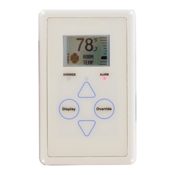
BASIC OPERATION Buttons and LEDs Sensor Operation LED Operation When power is fi rst applied to the OE217-02 E-BUS Digital Room Refer to Figure 3 for LED locations. Sensor, the sensor will display the Current Room Temperature and the Alarm LED: The Alarm LED will blink when there is an alarm from current setting of the slide offset. -
Page 5: Mounting And Wiring
MOUNTING AND WIRING Dimensions and Mounting Environmental Requirements Mounting The E-BUS Digital Room Sensor needs to be installed in an environment CAUTION: Do not touch the front face of the sensor while you that does not exceed a temperature greater than 150°F or less than -30°F are plugging in the modular sensor cable. -
Page 6: Sensor Operation
SENSOR SCREENS LCD Display Screens Outside Air Temperature Humidity Main Sensor Display Screens Status Screen There are 3 Main Sensor Display Screens. The fi rst screen displays the If the connected controller is Current Room Temperature, Operation Mode, Slide Offset, and RH (RH receiving an outdoor air tempera- is available on the OE217-03 Model). -
Page 7: Setpoint Adjust Screen
SENSOR SCREENS LCD Display Screens Setpoint Adjust Screen Operation Modes Refer to Figure 9 for operation mode screen examples. The different Touching <> or <> will dis- icons shown are a Snowfl ake for cooling mode, a Flame for heating play the Setpoint Adjust Screen. -
Page 8: Troubleshooting
TROUBLESHOOTING Troubleshooting the OE217-02 Temperature Only Sensor Measuring Digital Sensor Resistance OE217-02 - Temperature Only Sensor E-BUS Cable Disconnected From Sensor 1000 1002 1001 COMM 1001 LED1 .1uF 6.8uF 15pF .1uF 1502 3162 C1025 .1uF OE217-02 E-BUS Digital Room Sensor Back View NOTE: For This Test The Sensor Must Be Disconnected From Its E-BUS... -
Page 9: Temperature/Resistance Chart
TROUBLESHOOTING Temperature/Resistance Chart Temperature – Resis- Temperature – Resis- tance – for Type III 10K tance –for Type III 10K Ohm Thermistor Sensors Ohm Thermistor Sensors Temp Resistance Temp Resistance (ºF) (Ohms) (ºF) (Ohms) 11379 93333 11136 80531 10878 69822 10625 60552 10398... -
Page 10: Appendix
APPENDIX Sensor Confi guration and Test Screens Sensor Confi guration and Test Pixel Test Screen Screens To select the first option— Pixels—touch <> while at To access the Sensor Confi guration & Test Screens, you fi rst need to the Sensor Configuration & <Display>... - Page 11 APPENDIX Sensor Confi guration and Test Screens LCD Backlight Test Screens Address Screen To select the third option— To access the Address Screen, <Override> BACKLT—touch while at the Thermistor Averag- SENSOR while at the Sensor Confi guration ing Screen, (Figure 16), touch the COMM <Override>...
-
Page 12: Connecting The Digital Room Sensor To The Hvac Unit Controller
APPENDIX E-BUS Digital Room Sensor to HVAC Controller Wiring E-BUS Digital Room Sensor The OE217-02, OE217-03, or OE217-04 E-BUS Digital Room Sensor connects to the VCC-X / VCCX2 or VCB-X Controller with the EBC E-BUS expansion cable. The Digital Room Sensor should be mounted at approximately 5 Ft. above the fl... -
Page 13: Connecting A Wall Mounted E-Bus Co Sensor To The Hvac Unit Controller
APPENDIX Wall Mounted E-BUS CO Sensor Wiring E-BUS CO Wall Mounted Sensor It should be mounted at approximately 5 Ft. above the fl oor on the wall in an area that does not have drafts or is exposed to direct sunlight. See Figure 19 for wiring details and installation notes. -
Page 14: Connecting A Remote Sensor
APPENDIX Connecting a Remote Sensor Connecting a Remote Sensor so that the sensor will read the remote temperature input. Be sure to cut the ends of the wire close to the circuit board so that the sensor loop wire ends won’t short between each other. The remote sensor then wires to the If the job requires this Sensor to be mounted outside of a conditioned remote sensor terminal block on the back of the Digital Room Sensor. - Page 15 APPENDIX Connecting a Remote Sensor SHLD -COM +12Vdc Remove C1 Capacitor OE217-02, OE217-03 & OE217-04 E-BUS Digital Room Sensor Back View OE210 Space Sensor Shown With Temperature Sensor Back Cover Removed Back View Figure 21: Attaching the OE210 Space Room Sensor E-BUS Digital Room Sensor Technical Guide...
- Page 16 APPENDIX Connecting a Remote Sensor SHLD -COM +12Vdc Cut Wire Loop As Shown. OE217-02 E-BUS Digital Room Make Sure That The Wires Temperature Sensor Only Are Cut Close Enough To Back View The Circuit Board So They Can’t Touch Each Other. Sensor Shown With Back Cover Removed Figure 22: Wire Clipping Instructions For OE217-02 - Digital Room Temperature Only Sensor...
-
Page 17: Mounting Plate Dimensions
APPENDIX Mounting Plate Dimensions Optional Mounting Plate Included with the Digital Room Sensor is a mounting plate that can be used, if necessary, to cover the sensor sheet rock opening. This mounting plate screws onto the back of the housing base. The mounting plate is then mounted and covers the recessed space in the wall. - Page 18 NOTES E-BUS Digital Room Sensor Technical Guide...
- Page 19 NOTES E-BUS Digital Room Sensor Technical Guide...
- Page 20 2425 So. Yukon Ave • Tulsa, OK 74107-2728 www.aaon.com Ph: (918) 583-2266 • Fax: (918) 583-6094 AAON Manual Part Number: V08370 ® WattMaster Manual Form No: AA-EBUS-DRS-TGD-01K...
Need help?
Do you have a question about the AA-EBUS-DRS-TGD-01K and is the answer not in the manual?
Questions and answers