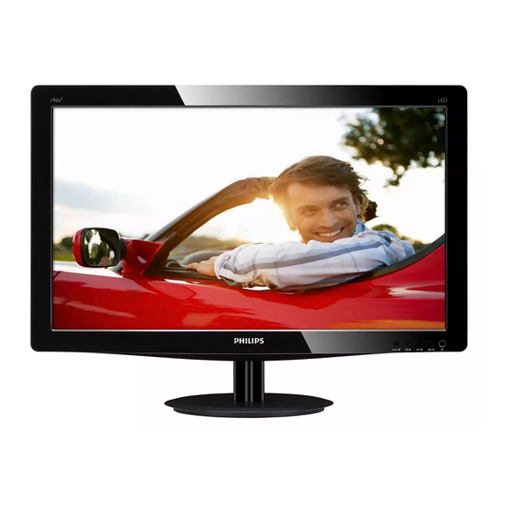
Philips 196V3LSB2/00 Service Manual

Philips 196V3LSB2/00 Service Manual

18.5 lcd color monitor
Hide thumbs Also See for 196V3LSB2/00:
Table of Contents

Advertisement

18.5 LCD Color Monitor
Service
Service
Service
Description
Table of Contents......................................................1
Revision List.............................................................2
Important Safety Notice............................................3
1. Monitor Specifications............................................4
2. LCD Monitor Description........................................8
3. Operation Instructions............................................8
3.1General Instructions........................................8
3.2 Control Buttons.............................................8
3.3 OSD Menu......................................................9
4. Input/output Specification..................................10
4.1 Input Signal Connector.....................................10
4.2 Resolution & Preset Modes.................................11
4.3 Pixel Defect Policy.......................................12
4.4 Failure Mode of Panel...................................14
5. Block Diagram...............................................15
6. Schematic Diagram.............................................. 17
6.1 Scaler Board..............................................17
6.2 Power Board..............................................22
ANY PERSON ATTEMPTING TO SERVICE THIS CHASSIS MUST FAMILIARIZE HIMSELF WITH THE
CHASSIS AND BE AWARE OF THE NECESSARY SAFETY PRECAUTIONS TO BE USED WHEN
SERVICING ELECTRONIC EQUIPMENT CONTAINING HIGH VOLTAGES.
CAUTION: USE A SEPARATE ISOLATION TRANSFOMER FOR THIS UNIT WHEN SERVICING
REFER TO BACK COVER FOR IMPORTANT SAFETY GUIDELINES
Copyright 2010 Philips Consumer Lifestyle
196V3LSB2/00
196V3LSB/00
196V3LSB2/01
196V3LSB/94
196V3LSB2/93
196V3LSB/75
196V3LSB2/94
196V3LSB/69
196V3LSB2/62
196V3LSB/93
196V3LSB2/69
196V3LSB/62
196V3LSB2/71
196V3LSB/55
196V3LSB2/73
196V3LSB/67
196V3LSB2/70
196V3LSB/71
196V3LSB2/45
196V3LSB/01
196V3LSB2/44
196V3LSB/70
196V3LSB2/55
196V3LSB2/78
SAFETY NOTICE
Subject to modification
196V3LAB/00
196V3LAB/01
196V3LAB/75
196V3LAB/69
Description
Page
6.3 Key Board.................................................24
6.4 Audio Board..............................................25
7. PCB Layout................................................26
7.1 Scaler Board............................................26
7.2 Audio Board.............................................26
7.3 Key Board..............................................26
7.4 Power Board.............................................27
8. Wiring Diagram.............................................28
9. Scaler Board Overview..................................30
10. Mechanical Instructions...............................31
11. Repair Flow Chart........................................34
12. ISP Instructions..................................................38
13. DDC Instructions................................................44
14. White Balance, Luminance Adjustment..............55
15. Monitor Exploded View.......................................57
16. Recommended & Spare Parts List...................59
17. Different Parts List......................................63
18. General Product Specification.........................67
May, 31, 2010
K
Chassis: Meridian 3
Page

Advertisement

Table of Contents
loading

Summary of Contents for Philips 196V3LSB2/00

  • Page 1 CHASSIS AND BE AWARE OF THE NECESSARY SAFETY PRECAUTIONS TO BE USED WHEN SERVICING ELECTRONIC EQUIPMENT CONTAINING HIGH VOLTAGES. CAUTION: USE A SEPARATE ISOLATION TRANSFOMER FOR THIS UNIT WHEN SERVICING REFER TO BACK COVER FOR IMPORTANT SAFETY GUIDELINES Copyright 2010 Philips Consumer Lifestyle Subject to modification May, 31, 2010...
  • Page 2 Aug,25,2011 Update BOM for 196V3LSB/69 196V3LSB/94 196V3LSB/97 Sep,6,2011 Update BOM for 196V3LSB/67 196V3LSB/71 Sep,27,2011 Update BOM for 196V3LSB/01 Oct,08,2011 Update BOM for 196V3LSB2/00 Oct,18,2011 Update BOM for 196V3LSB2/01 Oct,28,2011 Update BOM for 196V3LSB/75 196V3LSB2/93 196V3LSB2/94 Nov,4,2011 Update BOM for 196V3LSB2/62 196V3LSB2/69 196V3LSB/70 Update BOM for 196V3LSB2/71.
  • Page 3: Important Safety Notice

    Meridian 3 Important Safety Notice Proper service and repair is important to the safe, reliable operation of all Philips Company Equipment. The service procedures recommended by Philips and described in this service manual are effective methods of performing service operations. Some of these service operations require the use of tools specially designed for the purpose.
  • Page 4: Monitor Specifications

    Meridian 3 1. Monitor Specifications Technical specifications Picture/Display LCD Panel Type TFT-LCD Backlight Panel Size 18.5 W ( 47.01 c m) Aspect Ratio 16:9 Pixel Pitch 0.3 x 0.3 mm Brightness 250 cd/m² or 200 cd/m Smart Contrast 10,000,000:1 Contrast Ratio 1000:1 (typical) Response Time...
  • Page 5 Meridian 3 Normal Operation 13.42W 13.32W 13.30W (typ.) Sleep 0.5 W 0.5 W 0.5 W 0.5W 0.5 W 0.5W AC Input Voltage at 100V AC Input Voltage AC Input Voltage at 230V AC Heat Dissipation* AC +/- 5V AC, 50Hz +/- at 115V AC +/- 5V +/- 5V AC, 50Hz +/- 3Hz AC, 60Hz +/- 3Hz...
  • Page 6 CE Mark, FCC Class B, GOAST, SEMKO, TCO Certified(Only for selective Regulatory Approvals models), UL/cUL, BSMI, ISO9241-307 Cabinet Color Black Finish Glossy / Texture Note: 1. This data is subject to change without notice. 2. Go to www.philips.com/support to download the latest version of leaflet.
  • Page 7: Lcd Monitor Description

    Meridian 3 2. LCD Monitor Description The LCD monitor will contain a scaler board ,a power board ,an audio board , a key board and two speakers. The scaler board houses the flat panel control logic, brightness control logic and DDC. Monitor Block Diagram Flat Panel and LED Drive.
  • Page 8: General Instructions

    Meridian 3 3. Operating Instructions 3.1 General Instructions Connect to PC Press the power button to turn the monitor on or off. 1. Connect the power cord to the back of the monitor The other control knobs are located at front panel of firmly.
  • Page 9: Osd Menu

    Meridian 3 3.3 OSD Menu On-Screen Display (OSD) is a feature in all Philips LCD monitors. It allows an end user to adjust screen performance or select functions of the monitors directly through an on-screen instruction window. A user friendly on screen display interface is shown as below:...
  • Page 10: Input/Output Specification

    Meridian 3 4. Input/ output Specification 4.1 Input Signal Connector Analog Connectors Signal Name Signal Name Pin No. Pin No. DDC +3.3V or +5V Green/ SOG Logic GND Blue Sense (GND) Sense (GND) Bi-directional data Cable Detect (GND) H/H+V sync Red GND V-sync Green GND...
  • Page 11: Resolution & Preset Modes

    Meridian 3 4.2 Resolution & Preset Modes Maximum Resolution 1366 x 768 @ 60 Hz (analog input) 1366 x 768 @ 60 Hz (digital input) Recommended Resolution 1366 x 768 @ 60 Hz (digital input) H. freq (kHz) Resolution V. freq (Hz) 31.47 720 x 400 70.09...
  • Page 12: Pixel Defect Policy

    Meridian 3 4.3 Pixel Defect Policy each category. Philips strives to deliver the highest quality products. Bright dot defects We use some of the industry's most advanced Bright Dot Defects Bright dot defects appear as pixels manufacturing processes and practice stringent quality or sub pixels that are always lit or 'on'.
  • Page 13 In order to qualify for repair or replacement due to pixel defects during the warranty period, a TFT Monitor panel in a Philips flat panel monitor must have pixel or sub pixel defects exceeding the tolerances listed in the following tables.
  • Page 14: Failure Mode Of Panel

    Meridian 3 4.4 Failure Mode Of Panel Quick reference for failure mode of LCD panel this page presents problems that could be made by LCD panel. It is not necessary to repair circuit board. Simply follow the mechanical Polarizer has bubbles instruction on this manual to eliminate failure by replace LCD panel.
  • Page 15: Block Diagram

    Meridian 3 5. Block Diagram Scaler Board 12MHZ Panel Interface (X401) (CN409) Flash Memory Scaler IC NT68660FG Key control Interface Pm25LD020C (Include MCU, ADC, OSD) (CN404) (U402) (U401) H sync EEPROM EEPROM V sync CAT24C02 CAT24C02 (U105) (U101) D-Sub Connector Connector (CN102) (CN101)
  • Page 16 Meridian 3 Power Board AC input Bridge Rectifier +15V Rectifier diodes EMI filter Transformer and Filter Start Resistor Feedback PWM Control IC Circuit LD7750RGR Photocoupler ZD801 L801 (CN803) MOSFET (Q801) PWM Control Feedback Circuit ON/OFF TA9690GN-A1-0-TR (IC801)
  • Page 19 D403 NC/RLZ5.6B D402 NC/RLZ5.6B D401 NC/RLZ5.6B...
  • Page 20 C433...
  • Page 26: Scaler Board

    Meridian 3 7. Pcb Layout 715G4502M01000004C 7.1 Scaler Board ( Remark: Parts position can be searched by using FIND function in PDF. CN701 CN409 SEN4 R456 R455 C714 C709 C717 C707 C708 C701 R710 R798 C706 R711 R702 R713 R706 R704 C434 R716...
  • Page 27: Power Board

    Meridian 3 7.4 Power Board (715G4889P0E0000010) Remark: Parts position can be searched by using FIND function in PDF. GND1 J906 J905 CN801 D901 Q901 R935 J910 D904 L901 R932 ZD902 L801 C907 FB801 FB903 R919 J918 J904 J914 C931 C902 FB901 J907 D905...
  • Page 28: Wiring Diagram

    Meridian 1 8. Wiring Diagram 190V3LA Panel CN409 CN701 CN801 Power board Main board CN802 CN901 CN101 CN102 speaker speaker CN001 Key board...
  • Page 29 Meridian 3 190V3LS Panel CN409 CN701 CN801 Power board Main board CN802 CN901 CN101 CN102 CN001 Key board...
  • Page 30: Scaler Board Overview

    Meridian 3 9. Scaler Board Overview FFC Cable Scaler DC-DC Flash ROM VGA EEPROM DVI EEPROM Note: DVI EEPROM is available for selective models.
  • Page 31: Mechanical Instructions

    Meridian 3 10. Mechanical Instructions 2. Press the button and then remove the stand. press the two ribs and the remove hinge cover 3. Unscrew the five screws Step 1: Remove the base ,stand and rear cover 4. Open the latches and along the red arrowhead 1.
  • Page 32 Meridian 3 Step 2: Remove the main board 5. Tear out all tapes and unscrew two screws. 6. Disconnect all cables. 7. Unscrew the screws marked in red...
  • Page 33: Audio Board

    Meridian 3 8. Disconnect all cables. to scaler board to backlight to Panel to Power board to Key Board to audio board to Power Board to Power Board to scaler board...
  • Page 34: Repair Flow Chart

    Meridian 3 11. Repair Flow Chart 1. No Power No power Check power cable is Re-plug the power cable tightened? Check Power “On/Off” Turn on the Power “On/Off” switch is “On”? Check the LED Check the AC power indicator is OK? Replace the power board and check connections Replace main board and check connections Replace key board and check connections...
  • Page 35 Meridian 3 No Video (Power LED White) No Video (Power LED White) Press the power Replace the main board button is OK? Replace the power The end board and connection Replace the main The end board and connection Replace the FFC cable Check the FFC cable or panel or panel...
  • Page 36 Meridian 3 3. DIM DIM (image overlap, focus or flicker) Reset in factory mode The end Set to the optimal The end frequency, select the recommended frequency Readjust the phase and pixel The end clock in the user mode Pull out signal cable and Check the signal cable check “Self Test Feature and the PC...
  • Page 37 Meridian 3 4. Color is not optimal Color is not optimal Color shift Miss color Reset the factory mode Replace the signal cable In the user mode, set the “color settings” until customer satisfy The end Pull out the signal cable and check the screen color display is normal? Replace the signal cable or PC...
  • Page 38: Isp Instructions

    If the monitor can’t be power on, after programming, switch the source to “Gray” or “black and white” pattern and VGA mode, then do “Auto Color/Level”. Connect to DC 12V Input the PC LPT Connect this port to the Philips model VGA port 12.3 The process of ISP writing as follows:...
  • Page 39 Meridian 3 1. Double-click to running the program as follows: 2. Judge the monitor whether belong to “data in flash” or not, if belong to it, please click “option” item and select “FE2P Mode Enable”, otherwise, don’t do any actions. Like as below picture:...
  • Page 40 Meridian 3 3. Click “option” and select “Setup ISP tool ”, 4. Select the “NVT Type I (default)”, click the icon “Confirm Change”. and then click the “OK”...
  • Page 41 Meridian 3 Note: when click the icon “Confirm Change”, if the following picture appears, you must install the “ntport24”.
  • Page 42 Meridian 3 Click icon, choose the correct program, and then click open:...
  • Page 43 Meridian 3 6. Click icon. After display “Chip erase OK.”, “Programming Success”, “ISP OFF”, it means F/W updated OK, it will show as the follow picture: 12.4 Check the firmware version: Press buttons at the same time, power on the monitor, and then press the menu again; the picture will appear on the top left corner.
  • Page 44: Ddc Instructions

    13.2 Connect the EDID Board as follow: Note: when update, should make sure the LCD AC on, DC on. Connect this port to the Philips model DVI-D port Connect to the PC LPT Connect this port to the Philips model VGA port...
  • Page 45 Meridian 3 1. Rename the EDID data to “wa”, “wd”. 2. Put the “wa” and “wd” into a new folder, and then create another new folder named “ddc” (It must be “ddc” instead of other names). Step1: Must put the “ddc” folder and “TPVDDC6.0.exe” into the same folder. Step2: Must copy the folder which contains EDID data and “config”...
  • Page 46 Meridian 3 4. Click “Next”,it will show the picture as follow: 5. Click “OK” ,it will show the picture as follow:...
  • Page 47 Meridian 3 6. Key in the same 14 numbers in the Input SN and Verify SN. 7. Click “Program”, if it shows the below mistake, please try to write again.
  • Page 48 Meridian 3...
  • Page 49 Meridian 3 8. If it shows the below picture, it means the write is successful. 9. Click “ReadBoth”, if the DDC Write is OK, it will show the picture as follow: The information must be the same as the data you have loaded.
  • Page 50 Meridian 3 10. Click “program”, if the 12V connector is not OK, it will show the picture as follow: 11. Click “program”, if the cable connector is not OK, it will show the picture as follow:...
  • Page 51 Meridian 3 196V3L EDID Analog 00 01 02 03 04 05 06 07 08 09 0A 0B 0C 0D 0E 0F ----------------------------------------------- 00| 00 FF FF FF FF FF FF 00 41 0C 7F C0 01 01 01 01 10| 34 14 01 03 6E 29 17 78 2A A8 15 A6 54 4B 9B 25 20| 13 50 54 BD 4A 00 01 01 01 01 01 01 01 01 01 01 30| 01 01 01 01 01 01 66 21 56 AA 51 00 1E 30 46 8F 40| 33 00 99 E6 10 00 00 1E 00 00 00 FF 00 30 30 30...
  • Page 52 Established Timings 3:00 <-Standard Timing Identification:-> Standard Timing Identification: No Use <-Detailed Timing Descriptions:-> FC (Monitor Name) : Philips 196VL FD (Monitor Limits): Min. V. rate: 56 Hz Max. V. rate: 76 Hz Min. H. rate: 30 KHz Max. H. rate: 83 KHz Max.
  • Page 53 Meridian 3 Digital 00 01 02 03 04 05 06 07 08 09 0A 0B 0C 0D 0E 0F ----------------------------------------------- 00| 00 FF FF FF FF FF FF 00 41 0C 7F C0 01 01 01 01 10| 34 14 01 03 80 29 17 78 2A A8 15 A6 54 4B 9B 25 20| 13 50 54 BD 4A 00 01 01 01 01 01 01 01 01 01 01 30| 01 01 01 01 01 01 66 21 56 AA 51 00 1E 30 46 8F 40| 33 00 99 E6 10 00 00 1E 00 00 00 FF 00 30 30 30...
  • Page 54 Established Timings 3:00 <-Standard Timing Identification:-> Standard Timing Identification: No Use <-Detailed Timing Descriptions:-> FC (Monitor Name) : Philips 196VL FD (Monitor Limits): Min. V. rate: 56 Hz Max. V. rate: 76 Hz Min. H. rate: 30 KHz Max. H. rate: 83 KHz Max.
  • Page 55: White Balance, Luminance Adjustment

    Meridian 3 14. White Balance, Luminance Adjustment 1. Apparatuses and program: analyzer CA-210, PC, tool, FGA adjustment program (PHILIPS 190V3L.DDCI), Pattern generator. 2. Equipment installation: a. Connect analyzer CA-210 to PC by USB connector, install drive program CA-SDK Ver4.00 for CA-210 and restart PC after finish installing b.
  • Page 56 Meridian 3 5. Color Temp confirmation Connect the signal to the monitor, the monitor displays white-picture, use CA-210 to measure the Color Temp of the screen center and select the OSD to make sure whether the Color Temps accord with the SPEC. 6.
  • Page 59: Recommended & Spare Parts List

    Meridian 3 16. Recommended & Spare Parts List Recommended Parts List for 196V3LAB/00 ITEM LOCATION PCM CODES DESCRIPTION REMARK FQ101 705GFACS088 BEZEL ASSY FQ004 KEPCAQV6 KEY BOARD FQ419 078G020A--6--V SPEAKER FQ001 750GMT185W2C21M100 LM185WH2-TRC2 LTD FQ570 Q52G1801MNT058 MYLAR FQ003 PLPCB8561GQA5 POWER BOARD FQ005 AUPCAQV1 AUDIO BOARD...
  • Page 60 Meridian 3 IC902 056G-139--9 IC EL817M(X) photocoupler DIP-4 AC/DC CONVERTER IC801 056G-379185 TA9690GN-A1-0-TR SOP-24 AC/DC CONVERTER LD7750RGR IC901 056G-379190 SOP-7 IC903 056G-563354 Shunt. Reg. TL431-A-TA TO-92 Fast Blow Fuse ** F0603FA2000V032TM, 0FFST-0003A AEM, Ceramic, 32V, 2A, UL/CSA, 1.6X0.8X0.8, R/TP F901 084G--56-4W FUSE 4.0A 250V F902...
  • Page 61 Meridian 3 FQ118 A33G1224AFL-1B0100 HINGE COVER FQ111 705GFACS090 BASE ASSY U402 056G2233-11 IC Pm25LD020C-SCE SIOC-8(150mil) 2M U602 056G-662-48 ESD PROTECT AZC399-04S SOT23-6L U401 056G-562368 SCALER NT68660FG/B TQFP-100 IC AME8815BEGT180Z 1.5A/1.8V U703 056G-563161 SOT-223 U702 056G-563520 LDO LSP1117D33AG 1A 3.3V TO-252 U102 056G-662-48 ESD PROTECT AZC399-04S SOT23-6L...
  • Page 62 Meridian 3 E09501 F95G801830D300 LVDS CABLE 130mm 30P-30P E09501 F95G801830X300 LVDS CABLE 130mm 30P-30P source E09501 F95G801830R300 LVDS CABLE 130mm 30P-30P source Service Kit Description Part No. Picture EDID & ISP TOOL 715GT034-B...
  • Page 71: General Product Specification

    Meridian 2 18. General Product Specification V3 Series GENERAL PRODUCT SPECIFICATION Issued by: Wenchih Wang/Paul Tsai Revision History Ver. Date (yy.mm.dd) Author Brief Description 2011.01.01 UC Hsu Initial version 2011.05.19 Samou.Wu Update 9300K color temperature SPEC 2011.09.05 Wenhang.Zhang Add 18.5” / 19” / 20” 200nits panel spec Blue: Changes than last version Red: TBD Quick Specification table:...
  • Page 72 Meridian 3 Quick Specification table: Model Input Feature V3 L 1A1D or 1A V3 LA 1A1D + Audio Smart features SmartImage SmartResponse SmartPower SmartTouch SmartControl Pixel Orbiting...
  • Page 73: Table Of Contents

    Meridian 2 .CONTENTS FOREWORD ..........................75 PRODUCT PROFILE ........................75 EDID HEADER ............................75 CANNING FREQUENCIES ........................81 : ........................81 MBIENT TEMPERATURE OWER ANGE ............................81 ELECTRICAL CHARACTERISTICS ..................81 NTERFACE SIGNALS ..........................81 NTERFACE ............................. 83 IMING REQUIREMENT ..........................
  • Page 74 Meridian 3 5.12 LASTICS FLAMMABILITY ........................94 5.13 EXTURE LOSSING OF HOUSING ......................95 5.14 ILT AND SWIVEL BASE ........................... 95 5.15 ENSINGTON ..........................95 5.16 SHT 191/SHT560 ) ......95 RODUCT DIMENSION EIGHT EFER TO HILIPS APPROVED 5.17 RANSPORTATION ..........................
  • Page 75: Foreword

    5 Horizontal Frequency Range 30~60 KHz 6 Vertical Frequency Range 56~63Hz 7 Monitor Name (13 characters max.) Philips 166VL 196V3LSB,196V3LAB 1 User visible strings on .inf file Philips 196VL (19inch Wide LCD MONITOR 196V3L) 2 Manufacturer ID ( EDID data) 3 Product ID, "xxxx"...
  • Page 76 5 Horizontal Frequency Range 30~83 KHz 6 Vertical Frequency Range 56~76Hz 7 Monitor Name (13 characters max.) Philips 206VL 226V3LSB,226V3LAB 1 User visible strings on .inf file Philips 226VL (22inch Wide LCD MONITOR 226V3L) 2 Manufacturer ID ( EDID data) 3 Product ID, "xxxx"...
  • Page 77 Meridian 2 166V3 : Type NR. : CPT CLAA156WB-11A Resolution : 1366 x 768 (SXGA+) Outside dimensions : 359.8(H) x 210(V) Typ. x 5.5(D) Typ. Pitch (mm) : 0.252mm x 0.252mm Color pixel arrangement : RGB vertical stripe Display surface Glare Color depth : 16.7M (6 bit Hi-FRC)
  • Page 78 Meridian 3 : =160 for Up/Down (Typ) Contrast ratio : 1000:1 (Typ) White luminance : 250(Typ.) Color gamut 66% (Min.) Gate IC : N/A Source IC : N/A Response time : Tr + Tf <=5 ms (Typ) Vertical frequency range : 56~76Hz 200nits Type NR.
  • Page 79 Meridian 2 Backlight : LED Active area (W x H) : 408.24(H) x 255.15(V) mm View angle (CR>10) : =90 for Right/Left (Typ) : =50 for Up/Down (Typ) Contrast ratio : 600:1 (Typ) White luminance : 200(Typ.) Color gamut : 58% (min.) Gate IC : N/A Source IC...
  • Page 80 Meridian 3 White luminance : 200(Typ.) Color gamut : 58% (Min.) Gate IC : N/A Source IC : N/A Response time : Tr + Tf <=5 ms (Typ) Vertical frequency range : 48~76Hz 226V3 : Type NR. LNT LM215WF4-TRA2 Resolution : 1920 x 1080 (WSXGA+) Outside dimensions : 495.6(H) x 292.2(V) Typ.
  • Page 81: Scanning Frequencies

    Scaler should be capable of below items. 1) Scaler must support color engine for Image enhancement feature (SmartImage) 2) Scaler must have enough memory to support PerfecTune feature and Philips OSD 3) Scaler must support SmartContras,500K:1 DCR preferred 4) VGA signal Auto adjustment: Monitor automatically adjusts and optimizes resolution and frequency based on input signal defined by “Source”...
  • Page 82 Meridian 3 Audio channels: 2. DDC channel: Allows source to interrogate capabilities of sink. I²C signaling with 100 kHz clock. E-EDID data structure according to EIA/CEA-861D and VESA Enhanced EDID. Content protection: According to High-Definition Content Protection (HDCP) Specification 1.10. HDMI video input should support timing defined in CEA 861-D specification with extended EDID blocks Video Timing Support :...
  • Page 83: Interface

    Meridian 2 (DDC Signal) Maximum Capacitance : 50pF (HPD Signal) High Voltage Level : 2.4V – 5.0V Low Voltage Level : 0 – 0.4V Output Resistance : 1K ±20% (CEC Signal, not supported by this model) Input Low Voltage : <...
  • Page 84 Meridian 3 Red GND Green GND Blue GND DDC +3.3V or +5V Logic GND Sense (GND) Bi-directional data H/H+V sync V-sync Data clock DVI Cable The input signals are applied to the display through DVI-D cable. Length : Please refer to cable bundle summary file Connector type : DVI-D male with DDC-2B pin assignments White connector thumb-operated jackscrews...
  • Page 85 Meridian 2 Lane 0 (positive) Ground Lane 0 (negative) Lane 1 (positive) Ground Lane 1 (negative) Lane 2 (positive) Ground Lane 2 (negative) Lane 3 (positive) Ground Lane 3 (negative) connected to Ground connected to Ground Auxiliary Channel (positive) Ground Auxiliary Channel (negative) Hot Plug Detect Return for Power...
  • Page 86: Timing Requirement

    English, French, German, Spanish, Italian, Russian, Simplified Chinese, Portuguese, Turkish (9) Power On logo Power On Logo: Power On Show up Philips logo 3 seconds Change to input signal. This picture is reference only. The official drawing will send out by PM.
  • Page 87: Horizontal Scanning

    Meridian 2 Horizontal scanning Sync polarity : Positive or Negative Scanning frequency : 30 – 83 K Hz PS : Item 3.4 and 3.5 , as far as possible to be display (another Horizontal and Vertical) Vertical scanning Sync polarity : Positive or Negative Scanning frequency : 56 - 76 Hz...
  • Page 88: Vga Display Identification

    Meridian 3 Power saving mode to Normal: 3.8s(typ.) Note 2 : Measurement power Saving. VGA Display identification In accordance with VESA Display Channel Standard Ver.1.0 and DDC 2B capability DVI Display identification In accordance with DVI requirement (DDWG digital Visual Interface revision 1.0) use DDC-2B, DDC/CI, and EDID V1.3 USB support Connect the upstream port of the monitor to host PC’s USB port via USB cable.
  • Page 89: Power Sensor (Option)

    Meridian 2 3.17.2 Total Harmonic Distortion Total harmonic distortion shall be limited to 5% THD at the maximum wattage speaker rating specified in section 1.3, at 1 kHz, when the input is 1.0Vrms. 3.17.3 Power Handling Each speaker transducer shall accept up to the specified Wattage of audio power without damage or exceeding the frequency response and total harmonic distortion specifications.
  • Page 90 Meridian 3 User must be detected in the following range: 40 up to 100 cm (+ 20cm). Detection angle: +- 35 degree (for IR LED ) SENSOR key control, Adjust detection distances (0~4 scales), default is 3 , tolerance : ( 10cm) 0 : 0FF 1 : 90 cm 2 : 100 cm...
  • Page 91 Meridian 2 Lower down backlight Backlight & LCD panel PowerSensor No ACTION brightness shutdown Power Saving The following set-up’s will be supported Fig. 2: 2 monitors standing back to back. The monitors may influence each other. So Monitor 1 may produce unexpected brightness-switches in monitor 2 (and vice versa).
  • Page 92: Smart Power ( Option , Refer To Quick Specification Table )

    Meridian 3 Smart Power (option , refer to Quick specification table) To reduce the power by adjusting backlight , contrast and color. Algorithm is provided by Supplier. VISUAL CHARACTERISTICS Test conditions Unless otherwise specified, this specification is defined under the following conditions. (1) Input signal : As defined in 3.3, follow panel resolution, signal sources must have 75 ohm...
  • Page 93 Meridian 2 sRGB x = 0.313 ± 0.02 PerfecTune II y = 0.329 ± 0.02 5000K x = 0.345 ± 0.02 PerfecTune II y = 0.357 ± 0.02 Production alignment spec. CIE coordinates (x,y) 11500K x = 0.270 ± 0.006 PerfecTune II y = 0.281 ±...
  • Page 94: Mechanical Characteristics

    All Plastics to be Flame Retardant UL 94-HB or Better. Base / Pedestal to be Flame Retardant UL 94-HB. All major plastic parts (bezel, back cover) need to be molded from same resin. Plastic resin type selection should be referred to “plastic-Philips Pool monitor”.
  • Page 95: Tilt And Swivel Base

    Portrait Display : Kensington Lock Must meet Kensington_slot.spec “TYE-M0004”. MMD request metal plate in Kensington hole. Product dimension / Weight ( Refer to Philips approved SHT 191/SHT560 ) Transportation Transportation standards refer to UAN-D1534/00/01/02. Transportation packages Net weight Packaging and wrapping shall be sufficient to protect the product against damage or loss during shipment from the supplier to the destination specified in the purchase order.
  • Page 96: Pallet / Container Loading

    3. Cold Drop test (for design reference) Un-package test 1. Sine vibration (operating) 2. Half sine shock test (non operation) Pallet / Container loading (Refer to Philips approved SHT 560) Transportation standards refer to TYE-M0002 ,UAN-D1534 and UAW-0309. Air shipment - Sea container 20'(pallet/slip sheet)
  • Page 97: Transportation Tests

    Meridian 2 Note: recommend at 5 to 35 C, Humidity less than 60 % Transportation tests Refer to 5.15.2 Display disturbances from external environment According to IEC 801-2 for ESD disturbances Display disturbances to external environment...
  • Page 98 4. When the HV circuitry is operating properly there is no possibility of an x- tube must be the same type as the original, including suffix letter, or a Philips radiation problem. High voltage should always be kept at the manufacturer's approved type.

Table of Contents