Roland Fantom-S88 Service Notes
Hide thumbs
Also See for Fantom-S88:
- Owner's manual (228 pages) ,
- Quick start manual (52 pages) ,
- Turbostart (2 pages)
Table of Contents
Advertisement
Apr.2003
TABLE OF CONTENTS
SPECIFICATIONS.............................................................2
LOCATION OF CONTROLS ..........................................4
LOCATION OF CONTROLS PARTS LIST ...................6
EXPLODED VIEW ............................................................8
EXPLODED VIEW PARTS LIST .....................................9
WIRING DIAGRAM.......................................................10
PARTS LIST......................................................................12
CHECKING THE VERSION NUMBER.......................20
USERS DATA SAVE AND LOAD................................20
TEST MODE.....................................................................21
RESTORING THE FACTORY SETTINGS...................28
SYSTEM SOFTWARE UPDATE PROCEDURE .........28
KEYBOARD PARTS LIST ..............................................32
BLOCK DIAGRAM.........................................................34
CIRCUIT BOARD (MAIN) ............................................36
Copyright © 2003 ROLAND CORPORATION
All rights reserved. No part of this publication may be reproduced in any form without the written permission
of ROLAND CORPORATION.
CIRCUIT DIAGRAM (MAIN1).....................................38
CIRCUIT DIAGRAM (MAIN2).....................................40
CIRCUIT DIAGRAM (MAIN3).....................................42
CIRCUIT DIAGRAM (MAIN4).....................................44
CIRCUIT DIAGRAM (MAIN5).....................................46
CIRCUIT BOARD (JACK)..............................................48
CIRCUIT DIAGRAM (JACK-1).....................................52
CIRCUIT DIAGRAM (JACK-2).....................................54
CIRCUIT DIAGRAM (JACK-3).....................................56
CIRCUIT DIAGRAM (PANEL-C) ................................58
CIRCUIT BOARD (PANEL) ..........................................60
CIRCUIT DIAGRAM (PANEL-A/B) ...........................62
CIRCUIT BOARD (EXP).................................................64
CIRCUIT DIAGRAM (EXP)...........................................66
ERROR MESSAGES ........................................................68
17058150E0
SERVICE NOTES
Issued by RJA
Printed in Japan (0800) (NB)
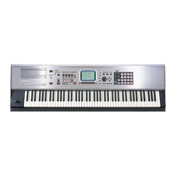
Fantom-S88
Advertisement
Table of Contents

Related Manuals for Roland Fantom-S88


Summary of Contents for Roland Fantom-S88
-
Page 1: Table Of Contents
BLOCK DIAGRAM............34 CIRCUIT DIAGRAM (EXP)...........66 CIRCUIT BOARD (MAIN) ..........36 ERROR MESSAGES ............68 Copyright © 2003 ROLAND CORPORATION All rights reserved. No part of this publication may be reproduced in any form without the written permission of ROLAND CORPORATION. 17058150E0 Printed in Japan (0800) (NB) -
Page 2: Specifications
Apr.2003 SPECIFICATIONS Recording Method Realtime recording, Step recording Effects Fantom-S88: Synthesizer Keyboard Multi-Effects: 3 systems, 78 types (Conforms to General MIDI 2 System) Chorus: 3 types Reverb: 5 types Input Effect: 6 types Keyboard Mastering Effect: 3-bands Compressor 88 keys (Progressive Hammer action mechanism and channel... - Page 3 Fantom-S88 Weight 29.5 kg / 65 lbs 1 oz Accessories Owner’s Manual English (#72238645) Japanese (#72238423) Sample Data (Audio) CD (#********) CD-ROM (Editor) (#03235778) Power Cord 100 V (#03340956) 120 V (#00894378) 230 V (#00894389) 240 VA (#23495124) 240 VE (#00907001)
-
Page 4: Location Of Controls
Apr.2003 Fantom-S88 LOCATION OF CONTROLS fig.panel-s88-rear fig.panel-s88-top... -
Page 5: Location Of Controls Parts List
Apr.2003 LOCATION OF CONTROLS PARTS LIST Part Code Part Name Description Q’ty 03127678 TOP PANEL 03125867 DISPLAY COVER 01124234 LCD UNIT LM320191 02452912 J R-KNOB SF-A BLK/LCG 03126167 12M/M ROTARY POTENTIOMETER EVJY10FB6A24 02452912 J R-KNOB SF-A BLK/LCG 03126178 9M/M ROTARY POTENTIOMETER EVUF2JFK3B14 22485303 D R-KNOB (ALPHA-DIAL) - Page 6 Fantom-S88...
-
Page 7: Exploded View
Apr.2003 EXPLODED VIEW fig.explo-s88... -
Page 8: Exploded View Parts List
Fantom-S88 EXPLODED VIEW PARTS LIST [PARTS] Part Code Part Name Description Q’ty 71905023 PB-H0203 BENDER TURBOLESS 01343089 ESCUTCHEON D-BEAM CONTROLLER ESCT BLK 03122067 RUBBER SW ESCT 01343101 D C-ESCT D C-ESCT BX1H BLK 03127678 TOP PANEL 03128289 SIDE PANEL L... -
Page 9: Wiring Diagram
Apr.2003 WIRING DIAGRAM... - Page 10 Fantom-S88 fig.wiringpohoto JACK BOARD PANEL-C BOARD PANEL-A BOARD LCD UNIT Part Code Part Name Description Q’ty 03120801 WIRING W3 CN601 on INLET to POWER SUPPLY UNIT 03234667 WIRING W1 CN10 on MAIN to POWER SUPPLY UNIT 03234678 BAN CARD BNCD-P=1.00-K-24-120...
-
Page 11: Parts List
Apr.2003 PARTS LIST fig.part1e CONSIDERATION ON PARTS ORDRING SAFETY PRECAUTIONS: When ordering any parts listed in the parts list, please specify the following items in the order sheet. The parts marked have PART NUMBER DESCRIPTION MODEL NUMBER safety-related characteristics. Use 22575241 Sharp Key C-20/50... - Page 12 Fantom-S88 POWER SUPPLY UNIT 01785823 A1DU2L3B034 SWITCHING REGULATOR NOTE: Replacement A1DU2L3B034 should be made on a unit base. BENDER UNIT 71905023 PB-H0203 BENDER TURBOLESS NOTE: Replacement PB-H0203 should be made on a unit base. KEYBOARD ASSY 72349667 KEYBOARD-AFT ASSY PA-588-F NOTE: See ‘KEYBOARD PARTS LIST’...
- Page 13 Apr.2003 00458312 NJM2360M IC (REGULATOR) IC504 on PANEL-C Board 01783523 TC74VHCT245AFT (EL) IC (CMOS) IC301 on LCD Board 01783656 HD74HC4053FPEL IC CMOS IC23 on JACK Board 02451712 HD74LV14ATELL IC (CMOS) IC1 on JACK Board 02565390 GP1FA501TZ TX IC (OPTICAL CONNECTOR) CN11 on JACK Board 01785012 HA17324...
- Page 14 Fantom-S88 DIODE 01897190 TLOU1002 (ORANGE) LED513,LED514,LED517,LED507,LED511, LED512,LED526,LED527,LED528,LED521, LED524,LED525,LED518,LED519,LED520, LED504,LED505,LED506, on PANEL-C Board 01900612 TPS611 DIODE Q1 on PANEL-A Board 02125167 SLI-343DCT32W LED (YELOW) LED17,LED3,LED16,LED15,LED11,LED10,LED8, LED4,LED2,LED1,LED9,LED5,LED7 on PANEL-A Board,LED510,LED516,LED502, LED503,LED509, on PANEL-C Board 02781290 RB161L-40 TE25 SCHOTTKY DIODE D3,D2 on Main board...
- Page 15 Apr.2003 RESISTOR 00567289 RPC05T 103 J MTL.FILM RESISTOR R174,R166,R165,R164,R139,R134,R175,R118,R119, R176,R43,R112,R242,R188,R243,R244,R264,R311, R313,R238,R22,R93,R92,R90,R84,R82,R80,R44, R94,R17,R33,R23,R24,R25,R27,R111,R35,R241, R39,R40,R42,R13,R36,R107,R105,R103,R95 on Main Board,R2,R6,R10 on EXP BASE Board, R12,R2,R5,R208,R207,R203,R11,R202,R13,R14, R38,R86,R96,R127,R135,R148,R165,R106,R182, R10,R88 on JACK Board 00567312 RPC05T 183 J MTL.FILM RESISTOR R106 on Main board,R518 on PANEL-C Board 00567323 RPC05T 223 J MTL.FILM RESISTOR R164,R163,R180,R181 on JACK Board...
- Page 16 Fantom-S88 POTENTIOMETER 03126167 EVJY10FB6A24 12M/M ROTARY POTENTIOMETER VR3,VR1 on PANEL-A Board 03126178 EVUF2JFK3B14 9M/M ROTARY POTENTIOMETER VR2,VR4,VR6,VR5 on PANEL-A Board 03126189 EVUF2AE17B14 9M/M ROTARY POTENTIOMETER VR501 on PANEL-C Board CAPACITOR 01674701 ECJ1VF1E104Z 0.1UF/16VK CERAMIC CAPACITOR C190,C179,C134,C182,C184,C185,C189,C199, C202,C197,C196,C186,C157,C374,C138,C140, C141,C142,C143,C144,C153,C154,C181,C156, C178,C158,C159,C160,C161,C162,C163,C169, C170,C171,C173,C176,C177,C155,C334,C200,...
- Page 17 Apr.2003 CAPACITOR 02783412 6SVP150 OS-CON CHEMICAL CAPACITOR C244,C254,C262 on Main board 02894390 RA2-25V330MC-T2 CHEMICAL CAPACITOR C169,C215,C214,C219,C217 on JACK Board 13519641 DD308-959F104Z50 CERAMIC CAPACITOR C13,C12,C5,C2,C30,C4,C15,C20,C21,C1,C25, C3,C31,C24 on PANEL-A Board 13519661 DD104-989SL150J50 CERAMIC CAPACITOR C10,C11 on PANEL-A Board 13529509 DD106-999F103Z50 CERAMIC CAPACITOR C14 on PANEL-A Board 13639150M0 ECEA1CKS100B 10UF/16V...
- Page 18 Fantom-S88 WIRING, CABLE 03236412 BAN CARD BNCD-P=1.00-K-40-550 CN7 on JACK to CN501 on PANEL-C 03236423 BAN CARD BNCD-P=1.00-K-38-450 CN5 on JACK to CN2 on PANEL-A 03129301 BAN CARD BNCD-P=1.00-K-10-400 CN6 on JACK to CN201 on PANEL-B 03129323 BAN CARD BNCD-P=1.00-K-34-60...
-
Page 19: Checking The Version Number
Apr.2003 CHECKING THE VERSION USERS DATA SAVE AND NUMBER LOAD Procedure Backing Up User Data Turn on the power of the Fantom-S. (User Backup) Press the [MENU] button to access the Menu window. Use the [CURSOR] up/down buttons to select “System,” and then press Here’s how all user data in the user area can be saved on a memory card. -
Page 20: Test Mode
Fantom-S88 TEST MODE When you press the [2] button (LINE TEST), the LCD display will show as follows, and Test mode will start up. fig.0-2_70 Required equipment Monitor speakers MIDI cables Audio cables PCS-31 (stereo phone plug <=> monaural phone plug x 2) - Page 21 Apr.2003 2. DEVICE test 15. Switch1 & LED 16. Switch2 This tests various devices located on the main board. 17. Keyboard When you enter the DEVICE test, the LCD display will show as follows, and device testing will begin automatically. 18.
- Page 22 Fantom-S88 4. Expansion Board test Insert the SmartMedia you provided (formatted; with protect label affixed) into the SmartMedia slot. This tests the Expansion Board socket and peripheral circuits. When the test result is OK, the display will indicate “Protect=OK Please, When you enter the Expansion Board test, the LCD display will show as Remove The Card”.
- Page 23 Apr.2003 8. D-Beam Adjustment test Verify that the LCD display shows a sawtooth wave above and a sine wave below, as follows. This adjusts the sensitivity of the [D BEAM] controller. fig.7-3_70 This adjustment sets the optimal sensitivity for the controller by making adjustments for two distances from the [D BEAM] controller;...
- Page 24 Fantom-S88 11. Pad Velocity First you will test the [D BEAM] controller. The LCD display will show “Max.” This tests [DYNAMIC PAD] operation. Place your hand above the [D BEAM] controller, and move that hand When you enter the Pad Velocity test, every [DYNAMIC PAD] will blink, and downward.
- Page 25 Apr.2003 13. Encoder 15. Switch1 & LED When you enter the Encoder test, the LCD display will show as follows. This tests the operation of LED-equipped switches. fig.13-1_70 When you enter the Switch 1 & LED test, the LCD display will show as follows.
- Page 26 Fantom-S88 17. Keyboard When you press the [8] button you will proceed to the four-level grayscale test. The LCD display will show as follows. This tests the keyboard. fig.18-2_70 When you enter the keyboard test, the LCD display will show as follows.
-
Page 27: Restoring The Factory Settings
Apr.2003 19. USB When the factory reset is completed, the LCD display will show as follows, and you will exit Test mode. This tests USB operation. fig.20-3_70 When you enter the USB test, the LCD display will show as follows. fig.19-1_70 Turn off the power of the Fantom. - Page 28 Fantom-S88 1. Updating from a computer via a USB cable Press buttons in the order of [SHIFT] [8]. The “Service Utility” screen will appear, and the LCD display will show as follows. Required items fig.up3 • UPDATE DATA FOR SERVICE CD-ROM (#17041312) •...
- Page 29 “Roland” folder of the CD-ROM. • Computer (the OS can be either Windows Me, Windows 2000, or Windows XP) 15. Copy the file “fans.bin” file (located within the “Roland” folder) to the • You cannot use a Mac under any circumstances. Fantom-S (removable disk).
- Page 30 Fantom-S88 11. Use [1 ( )] [2 ( )] to select “Version Info.” The Version Info screen will 15. Press the [ENTER] button. After a time, the display will indicate appear, and the LCD display will show as follows. “Completed. Please, PowerOff.” The update procedure has been completed.
-
Page 31: Keyboard Parts List
Apr.2003 KEYBOARD PARTS LIST fig.keyboard-pl SCREW M3X10 BINDING B-TITE FE ZC SCREW 3X6 BINDING TAPTITE P FE ZC * :Item 15 marked * is included in each unit of 14. The following parts are not included the Keyboard Assy. - Page 32 Fantom-S88...
-
Page 33: Block Diagram
Apr.2003 Fantom-S88 BLOCK DIAGRAM fig.block-s88 PANEL-A,B,C BOARD LCD UNIT CARD BOARD Smart Media D-Beam QVGA DynamicPAD 320x240dot 3.3V only LCD RELAY 128MB buffer 3.3V=>5V BOARD 20.000MHz SDRAM Flash ROM Flash ROM IC2,IC6 H8/3061 128Mbit x 2 IC19 IC53 20MHz aftertouch... -
Page 34: Circuit Board (Main)
Apr.2003 Fantom-S88 CIRCUIT BOARD (MAIN) Main_compo/Main_foil View from components side View from foil side... -
Page 35: Circuit Diagram (Main1)
Apr.2003 Fantom-S88 CIRCUIT DIAGRAM (MAIN1) fig.main-1 BA2:21 BD0:16 3. 3 EEPDI HD6417706F133 3. 3 XWE3 XWE3 3. 3 W E 3 / D Q M U U/ICIOWR/PTC[2] XWE2 XWE2 W E 2 / DQMUL/ICIORD/PTC[1] DQ15 XWE1 XWE1 RA12 10/16 BS/PTC[0]... -
Page 36: Circuit Diagram (Main2)
Apr.2003 Fantom-S88 CIRCUIT DIAGRAM (MAIN2) fig.main-2 BA2:21 A0:1 BD0:16 IC19 DQ15/A-1 DQ14 DQ13 DQ12 DQ11 3. 3 BA17 DQ10 BA16 BA15 BA14 BA13 BA12 IC20 BA11 10/16 IC21 DSA11 DD31 BA10 DQ15 TC200E1005AF-11(BA) DSA10 DD30 A10/AP DQ14 DSA9 DD29 DQ13... -
Page 37: Circuit Diagram (Main3)
Apr.2003 Fantom-S88 CIRCUIT DIAGRAM (MAIN3) fig.main-3 BA1:8 BD0:16 RA90 IC26B 3. 3 3. 3 R130 C151 10/16 C152 10/16 HD74LV125AT XWDMCS4 MCLK C153 C154 XWDMCS3 XNOSRX4 IC26A IC26C C155 C156 IC87A XWDMCS2 R100 C157 C158 XWDMCS1 C159 C160 XWCS4 XWDMCS4... -
Page 38: Circuit Diagram (Main4)
Apr.2003 Fantom-S88 CIRCUIT DIAGRAM (MAIN4) fig.main-4 BA0:23 BD0:16 3. 3 C222 IC79B 3. 3 C224 HD74LV139AT IC47A XBRD C225 XSMRE HD74LV32AT C226 3. 3 IC14D C227 IC13B XCS4 C228 IC47B R133 R134 XBWE0 C229 3. 3 C230 XSMWE 2.2k XBRD... -
Page 39: Circuit Diagram (Main5)
Apr.2003 Fantom-S88 CIRCUIT DIAGRAM (MAIN5) fig.main-5 MA147-(TX) R159 4.7k IC58 BIAS + 15 TER1 TER2 TER3 TA7805F M1698 M1698 M1698 R161 C267 4.7k C266 C269 C270 C271 C272 C273 10/16 10/16 10/16 DIR_INL R163 R162 R164 4.7k C274 R165 R166... -
Page 40: Circuit Board (Jack)
Apr.2003 Fantom-S88 CIRCUIT BOARD (JACK) View from components side... - Page 41 Apr.2003 Fantom-S88 CIRCUIT BOARD (JACK) View from foil side...
-
Page 42: Circuit Diagram (Jack-1)
Apr.2003 Fantom-S88 CIRCUIT DIAGRAM (JACK-1) fig.JACK-1 N1608Z N1608Z N1608Z N1608Z To: MAIN BOARD CN9 N1608Z N1608Z N1608Z XRST_SUB XRST5 XRST_IN 470/6.3 XRST_SUB SH3_TXD0 H8S_RXD1 SH3_RXD0 H8S_TXD1 SH3_XCTS2 H8_XCTS IC1G SH3_XRTS2 H8_XRTS HD74LV14ATELL SH3_TXD2 H8_RXD0 SH3_RXD2 H8_TXD0 ENC_B HD74LV14ATELL IC1A IC1B... -
Page 43: Circuit Diagram (Jack-2)
Apr.2003 Fantom-S88 CIRCUIT DIAGRAM (JACK-2) fig.jack-2 To:PANEL-A BOARD LS[0..3] TC74VHC138F RA24 SSS7 SSS6 SSS5 LLS5 RN2427 PLAY_GREEN SSS4 LLD4 RN2427 RN2427 SSS3 2SC4081 LLS4 RN2427 SSS2 BEAT_GREEN LLD3 RN2427 SSS1 LLD7 RN2427 SSS0 LLD2 RN2427 LLD5 PLAY_RED RA25 LLD1 LLS6... -
Page 44: Circuit Diagram (Jack-3)
Apr.2003 Fantom-S88 CIRCUIT DIAGRAM (JACK-3) fig.jack-3 R227 + 15 R111 + 15 R228 5.6K CN10 R112 5.6K B14B-PH-K-S A U DIO_IN_RTN_L C127 C225 C128 A U DIO_IN_RTN_R C129 100/25 TER1 TER2 TER3 R188 R114 A U D I O _IN_SEND_R... -
Page 45: Circuit Diagram (Panel-C)
Apr.2003 Fantom-S88 CIRCUIT DIAGRAM (PANEL-C) fig.panel-c DA501 R501 PTN501 PTN502 PTN503 PTN504 IC501 WRITE PAD04 YCOM R502 PAD08 XCOM CBN-M-1 CBN-M-1 CBN-M-1 CBN-M-1 PAD00 PAD_D R503 SW501 PAD12 PAD-13 PAD-14 PAD-15 PAD-16 EVQ11A05R PAD13 470k IC502A PAD15 PAD15 PAD01 HA17324ARPEL... -
Page 46: Circuit Board (Panel)
Apr.2003 Fantom-S88 CIRCUIT BOARD (PANEL) View from components side... -
Page 47: Circuit Diagram (Panel-A/B)
Apr.2003 Fantom-S88 CIRCUIT DIAGRAM (PANEL-A/B) fig.panel-a To:JACK BOARD CN5 100/16 OUTSEND_R 1SS133 1SS133 1SS133 1SS133 1SS133 1SS133 1SS133 1SS133 PADTRIGGER SOLOSYNTH INPUTS ASSIGN1 ASSIGN2 -OCT +OCT OUTSEND_L 100/16 EVQ11A05R EVQ11A05R EVQ11A05R EVQ11A05R EVQ11A05R EVQ11A05R EVQ11A05R EVQ11A05R (+5V) VR1A VR1B VR2A... -
Page 48: Circuit Board (Exp)
Apr.2003 CIRCUIT BOARD (EXP) View from components side... - Page 49 Fantom-S88 View from foil side...
-
Page 50: Circuit Diagram (Exp)
Apr.2003 Fantom-S88 CIRCUIT DIAGRAM (EXP) fig.exp 3 . 3 3WA23 TWA23 EWA23 3WA22 TWA22 EWA22 3WA21 TWA21 EWA21 3WA20 TWA20 EWA20 3WA19 TWA19 EWA19 To:MAIN BOARD 3WA18 TWA18 EWA18 D 3 . 3 3. 3 3 . 3 3 . 3 3 . -
Page 51: Error Messages
The contents of memory may have been damaged. Please perform the Factory Reset operation. If this does not resolve the problem, please contact your dealer or the nearest Roland Service Center. Memory Full! Saving is not possible because there is insufficient space Delete unneeded data.
Need help?
Do you have a question about the Fantom-S88 and is the answer not in the manual?
Questions and answers