
Related Manuals for H&H US-501


Summary of Contents for H&H US-501
- Page 1 US-501 Sewfree Ultrasonic Multi-Purpose Welder Operation Manual is powered by H&H Asia Group Limited service@hh.com.hk t = 852.24813068 f = 852.24813727 Room 1117, 11/F, Asia Trade Centre, 79 Lei Muk Road, Kwai Chung, N.T., Hong Kong...
-
Page 2: Preparation For Installation
US-501 operation manual Table of Contents Precautions Regarding to Safety Name Plate Introduction Specifications Features Identification of Components Front View Rear View Power ON/OFF Switch Welding Head Assembly Principle of Ultrasonic Welding Preparation for Installation Control Method Touch Screen Control Panel... - Page 3 US-501 operation manual Table of Contents (cont.) Maintenance Preventative Procedures for Replacing Parts Cutter Self Calibration Power Meter Trouble Shooting US-501 R02 13.07.09 Display version 4, PLC version 4 P.2 of 31...
- Page 4 US-501 operation manual > Precautions Regarding to Safety Please observe these safety tips for a safe, efficient, and injury free operation of your equipment. By strictly following all instructions contained in this manual you will certainly obtain an excellent performance from the use of this equipment for many years.
- Page 5 US-501 operation manual US-501 R02 13.07.09 Display version 4, PLC version 4 P.4 of 31...
- Page 6 US-501 operation manual > Precautions Regarding to Safety (cont.) US-501 R02 13.07.09 Display version 4, PLC version 4 P.5 of 31...
- Page 7 US-501 operation manual > Name Plate US-501 R02 13.07.09 Display version 4, PLC version 4 P.6 of 31...
- Page 8 > Introduction Thank you for choosing US-501 sewfree ultrasonic machine by H&H. The US-501 Sewfree Ultrasonic Multi-purpose Welder was specially designed for cutting and welding different type of fabric. Various operations such as ‘line bonding’, anti-fray cutting, button hole opening can be carried out using US-501.
- Page 9 US-501 operation manual > Specifications Model US-501 Voltage AC 220 V, single phase Frequency 50/60 Hz Power Consumption 700 W Cutting Frequency 1-25 stroke/sec Sonic Frequency 40 kHz Horn Width 3 mm Overall Dimensions 1.1 m (L) x 0.5 m (W) x 1.2 m (H)
- Page 10 US-501 operation manual > Features Quiet Ultrasonic System Microprocessor control with large panel touch screen operator interface Unique welding technique ensuring consistent welding energy control. Precise timing control resulted in no marking, over welding and skip welding during start and stop operation.
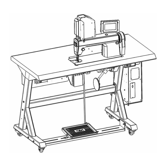
- Page 11 US-501 operation manual > Identification of Components >> Front View touch screen panel welding head assembly ultrasonic stack cover foot pedal knee switch transporting castor ultrasonic power supply electronic actuator sewing machine feed pitch adjusting knob US-501 R02 13.07.09 Display version 4, PLC version 4...
- Page 12 US-501 operation manual > Identification of Components (cont.) >> Rear View belt shroud ultrasonic power supply access panel cooling fan inlet circuit breaker reset access hole main electrical box table top US-501 R02 13.07.09 Display version 4, PLC version 4...
- Page 13 US-501 operation manual > Identification of Components (cont.) >> Power ON/OFF switch power ON button power OFF button >> Welding Head Assembly press foot feed dog bottom utility plate ultrasonic horn cutter bit cutter mount US-501 R02 13.07.09 Display version 4, PLC version 4...
- Page 14 US-501 is engineered to careful manage this vibrating energy in order to slice fabric consistently in single layer or multi-layer application.
- Page 15 US-501 operation manual > Preparation for Installation Installation must be carried out by authorized personnel. Follow the steps below: 1. Position the machine on a flat surface and allow at least 50cm clearance on both sides as well as the back side, this is essential to allow enough room for carrying out necessary service and maintenance 2.
- Page 16 US-501 operation manual > Control Method >> Touch Screen Control Panel Almost all setting and timing control of the machines can be input from the touch screen control panel. Use you fingertip to touch the parameter to be modified. Switch to different pages to modify other parameters (refer to section on control menu navigation).
- Page 17 > Control Method (cont.) >> Control Menu Navigation The US-501 has a number of parameters that can be adjusted according to the operational situations. These parameters are arranged in different menu pages on the touch screen control panel according to their functionality. The structure of the menu page arrangement is represented in the following diagram.
- Page 18 US-501 operation manual > Start Up and Shut Down Procedures Please take steps to follow the procedures described below: Location of power ON/OFF switch power ON button power OFF button >> Start up Procedures Turn on the machine by pressing the green power ON button The 1 page is welcome note will show once the machine is powered on.
- Page 19 US-501 operation manual > Start Up and Shut Down Procedures (cont.) >> Start up Procedures (cont.) The 2 page is program loading page, it will process for several seconds and carry to the main page. Briefly after the power is turned on, the electronic positioning system will direct the stamp to predefined position called home position.
- Page 20 US-501 operation manual > Basic Operation >> Control Panel Main page Going into the operation main page. Basic parameters are needed to be set before operating the machine. Refer to the corresponding sections for detail explanation. cutter assembly cutter pressure regulator (the number is the real time pressure, selecting range is -10 to +5)
- Page 21 US-501 operation manual > Basic Operation (cont.) >> Pattern Cutting Continuous Mode Pattern Cutting Mode press here to select the machine for normal or pattern cutting mode (default for continuous cutting) it is for setting the pattern cut repetition times (1=1 needle pitch, range 1 to 100)
-
Page 22: Cutter Calibration
US-501 operation manual > Basic Operation (cont.) >> Cutter Calibration cutter real position cutter position regulator cutter auto calibration switch cutter auto calibration cancel back to “main” page to next page R3: After operating with a period of time, the cutter will wear, the gap between the cutter and the sonic horn will need to readjust. - Page 23 US-501 operation manual > Basic Operation (cont.) >> Cutter Calibration (cont.) After press the #3 button and hold for 2 seconds, the machine itself will go through a “self-calibration” process and an alarm of “calibration in process” will flashing. Keep clear around the horn &...
- Page 24 US-501 operation manual > Basic Operation (cont.) >>Signal Feedback Monitoring It is listed all the feedback information of the sensors in this page to next page back to “main” page >> Alarm Page to next page back to “main” page...
- Page 25 US-501 operation manual > Basic Operation (cont.) >>Program Version to next page back to “main” page It is the end of this software version, press #1 or #2 button will back to the main page. US-501 R02 13.07.09 Display version 4, PLC version 4...
- Page 26 US-501 operation manual > Basic Operation (cont.) >> Procedures of Basic Cutting Set the sonic power to setting ‘8’, pressure to ‘2’. This should be a fair setting to start with. Raise the press foot by pressing on the knee switch and hold.
- Page 27 US-501 operation manual > Maintenance >> Preventative In order to keep the machine in top running condition, regular maintenance is important for trouble free operation. This will minimize possible down time and to prolong machine life. Daily Check the motion of the machine for smoothness and strange noise, especially high ...
- Page 28 US-501 operation manual > Maintenance (cont.) >> Procedures for Replacing Parts Cutter bit Turn off the machine. Unscrew the securing screw and tap out the cutter bit from the side. Replace another cutter bit. The bit is designed to be able to move from left to right in a range of about 5 mm.
- Page 29 US-501 operation manual > Maintenance (cont.) >> Procedures for Replacing Parts (cont.) Cutter bit (cont.) Loose the 2 securing screws slightly so that the mount can be pivoted. Push the cutter down so that the cutting edge will be in contact with the horn face. Pivot the mount slightly so that the contacting area will be a line rather than a point.
- Page 30 US-501 operation manual > Maintenance (cont.) >> Cutter Self Calibration Whenever a new cutter bit is installed or other related parts are serviced, due to slight dimensional variation, the depth of the cutting may have changed. Hence, the machine must be re-calibrated before the machine can be operated properly.
- Page 31 US-501 operation manual > Maintenance (cont.) >> Cutter Self Calibration (cont.) To initialize self calibration 1. Press and hold the self calibration button for 2 seconds to initialize the self calibration sequence. 2. The actuator system will slowly move the cutter toward the horn face.
- Page 32 US-501 operation manual > Maintenance (cont.) >> Power Meter Ultrasonic power meter There is a power meter on the page ‘main’ to monitor the ultrasonic power consumed by the system. The pointer inside will move up and down according to the power reading. The upper the pointer, the higher of the power is consuming.
-
Page 33: Troubleshooting
US-501 operation manual > Trouble Shooting Problem cause Solution Check the power supply connection Power cable or plug faulty Reset circuit breaker and investigate the cause Circuit breaker tripped No power in some places Press the power ON button (start)
Need help?
Do you have a question about the US-501 and is the answer not in the manual?
Questions and answers