
Related Manuals for HARVARD 33


Summary of Contents for HARVARD 33
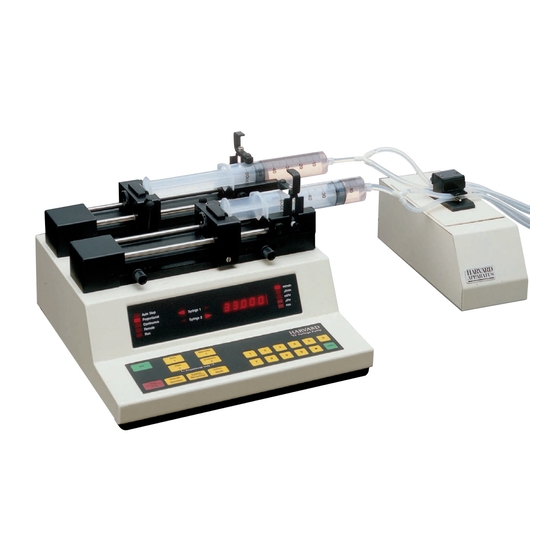
- Page 1 Model 33 Twin Syringe Pump User's Manual Syringe Pump Model 33 MA1-55-3333 Publication 5390-001 Revision B...
-
Page 2: Table Of Contents
Table of Contents SUBJECT PAGE Table of Contents ..............1 Warranty and Repair Information ........2 Specifications ..............3 Features ................4 Initial Setup ................5 Loading Syringes ..............6 User Interface..............7-8 Description of Keys ............8 Entering Data..............9 Operation ................10 Diameters ..............10 Pumping Rates............10 Selecting the Run Mode..........10 Selecting the Pumping Directions ......10 Running the Pump ............10 Single Syringe Operation ..........10... -
Page 3: Warranty And Repair Information
Warranty Harvard Apparatus warranties this instrument for a period of one year from date of pur- chase.At its option, Harvard Apparatus will repair or replace the unit if it is found to be defective as to workmanship or material. This warranty does not extend to damage resulting from misuse, neglect or abuse, normal wear and tear, or accident.This warranty extends only to the original customer purchaser. -
Page 4: Specifications
Specifications Harvard Pump 33 Specifications Accuracy ±0.35% Reproducibility ±0.1% Type Dual Syringe Infusion/Withdrawal Parallel/Reciprocal Size, L x W x H (286 x 311 x 152 mm) 11.25 x 12.25 x 6 in Weight (6.8 kg) 15 lbs Power 115/230 VAC, 50-60 Hz via selector switch, 45 W Fuse 1 A (115 V), 0.5 A (220 V) -
Page 5: Features
Features Pressure and Speed Pump 33 can deliver up to 53.346 ml/min with a 50 ml syringe, and is capable of pres- sures of up to 99.5 PSI with a 20 ml syringe. Independent Syringe Diameters and Rates In the Proportional Mode, separate syringe types and rates may be set. -
Page 6: Initial Setup
Initial Setup Read the manual. Locate the voltage selector switch on the rear panel of the pump and set it to the voltage being used. If other than 115VAC, 60 Hz is being used, the plug must be cut off and an appropriate plug installed, observing the polarity of the interna- tional line cord used: Brown –... -
Page 7: Loading Syringes
Loading Syringes SYRINGE 1 REFILL INFUSE LIMIT STOP LIMIT STOP LIMIT SWITCHES SYRINGE 2 Figure 1. Syringe Loading 1. The syringe holder and pusher block are fitted with movable retaining brackets which hold the syringe barrel and plunger when refilling.When loading the syringe into the pump, it is necessary to adjust these brackets.The pusher block is fitted with a mechanism to release the drive nut from the leadscrew.This allows the block to move freely so the syringe to be loaded. -
Page 8: User Interface
User Interface Auto Stop ml/min Syringe 1 µl/min Proportional Continuous ml/hr Syringe 2 µl/hr Remote Figure 2. User Interface The user interface consists of a display area and a keypad. The display consists of a 5 digit LED display and 14 LED indicators. The display will be showing either the default display or an informational message. -
Page 9: Description Of Keys
User Interface: Description of Keys Set Keys HARVARD Rate Diameter ‘33’ Syringe Pump Diameter Rate Proportional Only Stop Change Parallel Select Enter Reciprocal Mode Direction Data Entry Toggle Figure 3. Keypad Interface The keypad consists of 21 keys used for entering control information and data into the pump. -
Page 10: Entering Data
The keys in this group, when pressed successively, select different states. Each state change is accompanied by a corresponding change in status LED display. To operate, Pump 33 needs to know the diameter(s) of the syringes, the rate(s) of pumping, pumping directions, and the mode of operation. Except for Proportional mode, syringe 2 is assumed to be the same diameter as syringe 1 and will pump at same rate as syringe 1. -
Page 11: Operation
Operation Diameters The pump must be stopped when entering a diameter. Diameter 1 is the diameter of both syringes, except in Proportional mode. In Proportional mode, enter the diameter of each syringe separately; Diameter 1 for syringe 1 and Diameter 2 for syringe 2.When entering a diameter, the 2 direction LEDs corresponding to the syringe and the “mm”... -
Page 12: Valve Control Box
1. Pump to Valve Electrical Connections: The cable fitted with a male 3 pin connector must be connected to the female connector on the rear of the Model 33. The Model 33 should be turned off when making/breaking this connection. -
Page 13: Pinch Valve Connectors
Pinch Valve Connectors Top Tube Bottom Tube Valve Shown de-energized Figure 4. Pinch Valve Connections Fill Rear Bottom Bottom Front Bottom Bottom Output Figure 5. Continuous Delivery. Pump in Reciprocal Mode. Fill Rear Rear Bottom Bottom Fill Front Front Bottom Bottom Output Output... - Page 14 Stainless Steel Valve Connectors P = Com. B = Normally Open A = Normally Closed Rear Output Front Fill Figure 7. Continuous Delivery. Pump in Reciprocal Mode. Output Rear Output Front Rear Front Fill Fill Front Rear Figure 8. Dual Delivery followed by Refill. Pump in Parallel Mode. Swage lock fittings should be finger tight plus 1-1/4 turns.
-
Page 15: External Control And Interfaces
PORT #2 PORT #1 Figure 9. External Interface External devices that can be attached to the Pump 33 include external valves, pump chain, and TTL devices. See the appropriate appendixes for specification details on attaching devices. Attaching a Pump Chain On the back of the pump are two telephone jack type connectors. -
Page 16: Ttl Devices
External Control and Interfaces Attaching a Valve Control Accessory Box Attach the valve control cable to the pump’s accessory valve connection (see Figure 9). Refer to the Valve Control Box section. TTL Devices The pump does not need to be configured to attach a TTL device. To attach a TTL device, simply plug the appropriate TTL connector into the 9 pin connector on the rear of the pump. -
Page 17: Pump Chain Commands
In addition, this interface allows up to 100 Pump 33’s or, in certain cases, other RS-232 devices to be controlled from a single RS-232 communication port on a computer. Assign each pump in the pump chain a unique address from 0 to 99. -
Page 18: Pump Commands And Responses
Pump Chain Commands A prompt is a string of ASCII characters sent by a pump, indicating the pump’s address and its present state: <lf>, 1 or 2 digit address, prompt character Prompt Characters Meaning Pump stopped > Syringe 1 infusing <... - Page 19 Pump Chain Commands DIA [{A|B}] [<float>] Request to set or query syringe diameter settings. Set syringe 1 diameter: DIA diameter DIA A diameter Set syringe 2 diameter (only valid in proportional mode): DIA B diameter Corresponding syringe’s rate will be zeroed. Diameter is of the format: f f f f f f Units are millimeters.
- Page 20 Pump Chain Commands Query pumping direction of syringe 1: Response will be one of: INFUSE REFILL PAR [{ON|OFF}] Request to set or query Parallel or Reciprocal setting. Command Meaning SET: PAR ON Sets syringes to parallel pumping direction. PAR OFF Sets syringes to reciprocal pumping direction.
-
Page 21: Pump Chain Error Messages
Pump Chain Commands Pump Chain Error Messages Error messages are in the format: <lf>, <message>, <cr>, and are followed by a prompt. <Message> is one of the following: Possible Responses Meaning Syntax error in a received command Command “Not Applicable” at this time. “Out Of Range”. -
Page 22: Appendices
Appendix A: Syringe Diameters in mm Harvard Terumo SGE Scientific Stainless Steel Glass Engineering Size Diameter Size Diameter Size Diameter 3 cc 8.95 mm 8 cc 9.525 mm 13.00 25 µl 0.73 mm 19.130 15.80 1.03 28.600 20.15 1.46 34.900 23.10... -
Page 23: Nominal Min/Max Flow Rates
Appendix B: Nominal Min/Max Flow Rates Minimum flow rates are taken from the smallest inside diameters and maximum flow rates are taken from the largest inside diameters of the syringes supplied by the eleven most widely used syringe manufacturers. Nominal Minimum/Maximum Flow Rates for Various Syringes (Actual Limits will vary depending on manufacturer) Syringe µl/hr µl/min... -
Page 24: Command Information
Appendix C: Command Information Pump Chain Command Summary All spaces in command are ignored. Maximum 5 digits per integer, or float data. command = > [<adr>] [<cmd>] <CR> = > [d]d 1 or 2 digit address => Start pump Stop pump RAT [A] [<float>... -
Page 25: Rs-232 Specifications
Appendix D: RS-232 Specifications Pump Chain Transmit Receive Transmit Pump Port 1: Computer Receive control side Pump Port 2: Connection for remainder of pump chain Baud Rate: 300, 1200, 2400 or 9600 Word Size: Parity: none Stop Bits: Port #2 Port #1 (in) (out) -
Page 26: Pump To Pc Connection
Appendix F: Pump to PC Connection “Pump” 4400 22/2000 Front View RJ12 - 6 x 6 RJ11/RJ12 Publication 5390-001 Revision B... -
Page 27: Maintenance
Appendix G: Maintenance Pump 33 requires no special maintenance other than keeping it clean by avoiding acci- dental spills of pumped material. The two guide rods and the lead screw should be sparingly lubricated periodically with the Magnalube-G R grease provided with the pump. This Teflon R based grease is available either from Harvard Apparatus or Carleton-Stuart Corp. -
Page 28: Troubleshooting
Appendix H: Troubleshooting RS-232 Difficulties Verify that the baud rates and data framing parameters on all devices are the same. With a pump chain, a “Communication timeout” error on a computer is usually caused by the computer errantly handshaking on the RTS, CS and/or DSR lines. Verify pins 4, 5 and 6, on the 25 pin connector, are jumpered on the computer side of the cable. -
Page 29: Accessories
Appendix J: Custom Applications The Harvard 33 Syringe Pump lends itself to a multitude of OEM industrial applica- tions, for all types of custom pumping or pilot plant applications. Please contact the Harvard Development Group if we can be of help.
Need help?
Do you have a question about the 33 and is the answer not in the manual?
Questions and answers